CN100570469C - Shutter device and picture pick-up device - Google Patents
Shutter device and picture pick-up device Download PDFInfo
- Publication number
- CN100570469C CN100570469C CNB2007101525651A CN200710152565A CN100570469C CN 100570469 C CN100570469 C CN 100570469C CN B2007101525651 A CNB2007101525651 A CN B2007101525651A CN 200710152565 A CN200710152565 A CN 200710152565A CN 100570469 C CN100570469 C CN 100570469C
- Authority
- CN
- China
- Prior art keywords
- blade
- shutter
- time
- slit
- vane member
- Prior art date
- Legal status (The legal status is an assumption and is not a legal conclusion. Google has not performed a legal analysis and makes no representation as to the accuracy of the status listed.)
- Expired - Fee Related
Links
Images


Classifications
-
- G—PHYSICS
- G03—PHOTOGRAPHY; CINEMATOGRAPHY; ANALOGOUS TECHNIQUES USING WAVES OTHER THAN OPTICAL WAVES; ELECTROGRAPHY; HOLOGRAPHY
- G03B—APPARATUS OR ARRANGEMENTS FOR TAKING PHOTOGRAPHS OR FOR PROJECTING OR VIEWING THEM; APPARATUS OR ARRANGEMENTS EMPLOYING ANALOGOUS TECHNIQUES USING WAVES OTHER THAN OPTICAL WAVES; ACCESSORIES THEREFOR
- G03B9/00—Exposure-making shutters; Diaphragms
- G03B9/08—Shutters
- G03B9/10—Blade or disc rotating or pivoting about axis normal to its plane
Landscapes
- Physics & Mathematics (AREA)
- General Physics & Mathematics (AREA)
- Shutters For Cameras (AREA)
Abstract
A kind of shutter device and picture pick-up device, this shutter device comprises vane member and detecting unit.Vane member comprises first blade, second blade, test section and restrictions.Vane member is controlled at the time of the exposure of carrying out on the recording medium based on the size of the width of slit.Slit comprises slit portion, and provides slit when first blade and second blade are advanced.Slit portion is separately positioned on test section and restrictions.Detecting unit detects the state of slit width.Notch is set at vane member, makes that the width of slit portion at test section place is bigger than the width of the slit portion at restrictions place.Detect test section by detecting unit.The restrictions restriction time shutter.
Description
Technical field
The present invention relates to a kind of shutter device that comprises first blade and second blade, and relate to a kind of picture pick-up device.
Background technology
Usually, as the shutter that in single-lens reflex camera, uses, use the focal plane shutter that comprises two groups of light shielding members, first blade (the first act) and second blade (act 2).Before the exposure, first blade of focal plane shutter covers peristome.Then, when photographing, at first, first blade is kept out of the way from peristome, with the exposure of beginning on shooting face.Thereafter, through after the schedule time, the shutter device operation makes second blade cover peristome.
When focal plane shutter being carried out when control high speed time, reduce the width of the slit that forms by first blade and second part of vane, control to realize the high speed time.
Japanese kokai publication hei 6-265975 communique has been discussed the focal plane shutter that comprises detecting unit, this detecting unit utilizes light emitting diode and phototransistor to detect the width of the slit that is formed by first blade and second part of vane, and promptly shutter-blade is opened the time.In addition, discussed and to have detected the whether shutter device in predetermined scope of shutter precision.
In recent years, shutter speed significantly improves, and the width of the slit that is formed by first blade and second part of vane reduces.Therefore, with the same in the shutter device of in above-mentioned document, discussing, have following problem: when detect by the detecting unit that utilizes light emitting diode and phototransistor blade open the time time, open the time and open at the slit of reality and produce difference between the time by the detected slit of detecting unit.
The shutter of the prior art is described with reference to figure 4 to Fig. 9.Fig. 4 is the front view of the focal plane shutter of prior art, and the state of the charging (charge) of finishing blade is shown.Reference numeral 1 is illustrated in the shutter base plate that central portion has peristome 1a.Thereby Reference numeral 21 expression is pivotally mounted to the axle 1c of shutter base plate 1 and by the torque spring (not shown) along the rotating first vane drive bar of the clockwise application of force among Fig. 4.The first vane drive bar 21 is provided with vane drive pin 21a at its illustrated right-hand member, and is connected to the first primary blades arm (explanation after a while).The first act armature (armature) 22 is installed to the illustrated top of the first vane drive bar 21.Under the state of finishing charging shown in Figure 4, first armature 22 contacts with the adsorption plane that is added the first blade electromagnet 23 that is connected to the base plate (not shown).
Thereby Reference numeral 24 expression is pivotally mounted to the axle 1d of shutter base plate 1 and by the torque spring (not shown) along the rotating second vane drive bar of the clockwise application of force among Fig. 4.The second vane drive bar 24 is provided with vane drive pin 24a at its illustrated right-hand member, and is connected to the second primary blades arm (explanation after a while).Act 2 armature 25 is installed to the illustrated top of the second vane drive bar 24.Under the state of finishing charging shown in Figure 4, the second blade armature 25 contacts with the adsorption plane of the second blade electromagnet 26 that is adhered to the base plate (not shown).
Fig. 5 is the front view of the state of finishing charging of blade.Fig. 6 is the rear perspective view of the state of finishing charging of blade.
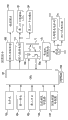
Fig. 7 is the block scheme of electrical structure that comprises the camera of above-mentioned focal plane shutter.The central processing unit (CPU) of the whole camera of Reference numeral 101 expression controls.Reference numeral 102 expressions store for example EEPROM of camera-enabled data.The main switch of Reference numeral 103 expression starting camera bodies.Reference numeral 104 expression is when the release-push (not shown) being pressed onto first switch that first travel position is connected when beginning for example photometering operation or focus detecting operation.The second switch that Reference numeral 105 expression is connected when release-push being pressed onto second travel position with the releasing operation that begins to be used to expose.Reference numeral 106 expression photometering sensors, the distance measurement sensor of known ccd linear sensor is used in Reference numeral 107 expressions.
The lens control circuit of the driving of the interchangeable phtographic lens 109 of Reference numeral 108 expression control single-lens reflex cameras.Reference numeral 110 expressions are connected to the shutter control circuit of first blade electromagnet 23 (operation of first blade unit 6 of its control focal plane shutter) and the second blade electromagnet 26 (operation of second blade unit 7 of its control focal plane shutter).Reference numeral 10 expressions comprise the above-mentioned PR element of LED 10a and PTR 10b.The PR element forms and makes CPU 101 controls from the light that LED 10a launches, and the projection light of LED 10a is reflected by catoptron 11, and this reflected light can be received by PTR 10b.In this structure, detect operation by the blade between PR element 10 and the catoptron 11.Reference numeral 111 expression drives catoptron charging mechanism 113 and shutter charging mechanism 114, drives catoptron (not shown) and the control drive electric motor to the charging bar 27 of shutter charging in the shooting operation process based on the control signal from electromotor control circuit 112.
Then, the operation that explanation is had camera the relevant part of said structure with operation focal plane shutter.
At first, under the state of first blade electromagnet 23 that makes shutter and the energising of the second blade electromagnet 26, the operation by motor 111 makes the catoptron (not shown) keep out of the way from light path of photography.Simultaneously, the operation by motor 111 makes charging bar 27 rotate counterclockwise from state shown in Figure 4, and makes the first vane drive bar 21 and the second vane drive bar 24 can be along clockwise rotating among Fig. 4 by driving stem spring (not shown) applied force.At this moment, the first blade electromagnet 23 and the second blade electromagnet 26 are in "on" position.Therefore, by the first blade electromagnet 23 and 26 absorption of the second blade electromagnet and maintenance the first act armature 22 and act 2 armature 25, make the first vane drive bar 21 and the second vane drive bar 24 are remained on state shown in Figure 4 respectively.Under this state, when making the first blade electromagnet 23 stop to switch on, make the first vane drive bar 21 along clockwise rotating among Fig. 4 by driving spring (not shown) applied force, the primary blades arm 2 (shown in Figure 5) of winning is also rotated.Like this, first blade unit 6 begins to open.
Then, when making the second blade electromagnet 26 stop to switch on, make the second vane drive bar 24 along clockwise rotating among Fig. 4, make the second primary blades arm 8 (shown in Figure 5) also rotate by driving spring (not shown) applied force.Like this, second blade unit 7 begins to close.The operation of shutter is controlled in the timing that makes the first blade electromagnet 23 and the second blade electromagnet 26 stop to switch on by control.
In the shutter operation process, make the LED 10a emission light of PR element 10, and received by PTR 10b from the light of catoptron 11 reflections hole 1b via shutter base plate 1.Thereby measure opening the time of blade.
Fig. 8 is illustrated in the shutter operation process, the variation of the output voltage of PTR 10b, and transverse axis is represented the time, and the longitudinal axis is represented the voltage of PTR 10b.The waveform 31 of acquisition in the time durations of opening shutter fully, thus utilize voltage judgment value 32 to obtain the measurement result of time T 1 as benchmark.
Fig. 9 is the rear perspective view that illustrates with the state of maximal rate time (1/8000 second) operation shutter.In order more easily to observe Fig. 9, not shown shutter base plate 1.The high speed time that the width of the slit S that is formed by first blade unit 6 and second blade unit 7 by control is realized focal plane shutter.Yet when reducing the width of slit S, shown in the waveform 33 as shown in Figure 8, second blade unit 7 arrived before first blade unit 6 is fully by PR element 10 fronts.Therefore, the voltage of the PTR 10b corresponding with the output voltage of PR element 10 is not the voltage of expression " complete bright state ", but the voltage of expression " dark state ".
In addition, when causing the shutter precision to reduce owing to for example variation of permanance and further reducing the width of slit S, shown in the waveform 34 as shown in Figure 8, the voltage of the PTR 10b corresponding with the output voltage of PR element 10 does not reach voltage judgment value 32.Therefore, the energy measurement shutter is not opened the time.
Under these conditions, even make great efforts to proofread and correct the variation of shutter precision or detect closing of blade, can not accurately carry out the correction of shutter precision variation and the detection that blade is closed.
Summary of the invention
Consider that above-mentioned situation made the present invention, and the invention provides and a kind ofly can accurately measure shutter device and the picture pick-up device that shutter is opened the time.
According to the present invention, shutter device comprises vane member and detecting unit.Vane member comprises first blade and second blade.Vane member is configured to be controlled at by the width of control slit the time of the exposure of carrying out on the shooting face.This slit when advancing, first blade and second blade is provided.Detecting unit detects the blade of vane member and opens the time.Notch is set at vane member, makes the detecting unit that is used for of slit detect blade and open the width of the part of time and become bigger than the width of the slit that is used to limit the time shutter.
According to the present invention, picture pick-up device comprises: vane member, it comprises first blade and second blade, and vane member is configured to be controlled at time of the exposure of carrying out on the shooting face by the width of control slit, and this slit is provided when first blade and second blade are advanced; And detecting unit, its blade that is configured to detect vane member is opened the time.Notch is set at vane member, makes the detecting unit that is used for of slit detect blade and open the width of the part of time and become bigger than the width of the slit that is used to limit the time shutter.
From the explanation of doing below in conjunction with accompanying drawing, other embodiments of the invention, aspect and advantage will become obviously, and in the drawings, identical Reference numeral is represented same or analogous part.
Description of drawings
The accompanying drawing of a part that is included in the instructions and constitutes instructions is used to explain principle of the present invention with embodiments of the invention have been described.
Fig. 1 is the front view of exemplary construction of the blade of focal plane shutter according to an exemplary embodiment of the present invention.
Fig. 2 is the rear perspective view of structure of the blade of focal plane shutter according to an exemplary embodiment of the present invention.
Fig. 3 is the process flow diagram of case step of operation that comprises the camera of focal plane shutter according to an exemplary embodiment of the present invention.
Fig. 4 is the front view of drive part of the focal plane shutter of prior art.
Fig. 5 is the front view of structure of blade of the focal plane shutter of prior art.
Fig. 6 is the rear perspective view of structure of blade of the focal plane shutter of prior art.
Fig. 7 comprises the focal plane shutter of prior art or according to the block scheme of the electrical structure of the camera of the focal plane shutter of exemplary embodiments.
Fig. 8 illustrates the variation of output voltage of PTR of the focal plane shutter of prior art.
Fig. 9 is the rear perspective view that the state that the focal plane shutter of prior art operating is shown.
Embodiment
To describe exemplary embodiments of the present invention, feature and aspect with reference to the accompanying drawings in detail.
First exemplary embodiments
Fig. 1 is the front view of exemplary construction of the major part of focal plane shutter according to an exemplary embodiment of the present invention.Fig. 2 is its rear perspective view, the state when shutter being shown advancing.For reduced graph 1 and Fig. 2, not shown shutter base plate.
In Fig. 1 and Fig. 2, Reference numeral 12 expressions first blade unit, Reference numeral 13 expressions second blade unit.Reference numeral 12a represents first blade of first blade unit 12, and Reference numeral 13a represents the one the second blades of second blade unit 13.Second blade to the quaterfoil, primary blades arm and the back blades arm of first blade unit 12 and second blade to the quaterfoil, primary blades arm and the back blades arm of second blade unit 13 are identical with the back blades arm with second blade to the quaterfoil, the primary blades arm of the example of prior art, therefore will no longer describe them below.
The first blade 12a and the one the second blade 13a have notch 12a1 and 13a1 respectively in each end by PR element 10 measuring slit width.Therefore, it is big to be positioned at the slit width of measurement section.Therefore,, that is to say, when the slit width S of shutter shown in Figure 2 becomes very little or becomes 0, provide the slit width S1 that is positioned at the measurement section place that notch 12a1 and 13a1 are set when the shutter precision reduces or blade when closing.Therefore, PR element 10 can be measured opening the time of the slit that formed by first blade unit 12 and second blade unit 13.
About desirable shutter, when the assembling shutter, the shutter precision depends on the error degree that equates with machine error (error) and electrical error sum.Error is more little, and the shutter precision is high more.
The detection that correction that the precision of the shutter that uses first blade unit 12 with said structure and second blade unit 13 changes and blade are closed will be described now.
At first, in the starting stage of assembling shutter, after adjusting the shutter precision, the output when the maximal rate time (for example 1/8000 second) comes measuring slit to pass through the time based on PR element 10, with Measuring Time T1.What time T 1 equaled the notch 12a1 at aperture time T (if the maximal rate time is 1/8000 second, then aperture time T is 0.122msec (millisecond)) and the place, end of the end that is separately positioned on the first blade 12a and the one the second blade 13a and 13a1 passes through time T p sum.
Even when storing by time T p and changing aperture time T, if the variation of the shutter precision that is caused by for example durable change does not take place, then following the maintenance.That is to say, for example, in the time of 1/500 second, T '=1.953msec, thus the Measuring Time T1 ' of this moment equals T '+Tp.Measuring Time T1 when at every turn photographing, thereby the measurement result in when photography is designated as T1 ", the aperture time of this moment is designated as T ".That is to say,
ΔT=T1″-(T″+Tp)
If the shutter precision does not change, then Δ T equals 0.For example, the correction (correction of the permanance of shutter just) that changes about precision, when aperture time is 1/8000 second, is setting exposure value and surpassing ± state of 0.3EV under, correction accuracy changes.When Δ T surpass+during 0.028msec (be+value when 0.3EV and aperture time are 1/8000 second is corresponding) with exposure value, perhaps be less than or equal to when Δ T becomes-0.024msec (with exposure value be-value when 0.3EV and aperture time are 1/8000 second is corresponding) time, the shutter control time proofreaied and correct.
The step of operation of shutter that will comprise the camera of focal plane shutter here, with reference to the flowchart text of figure 3 with structure shown in Figure 1.The example circuit structure of this camera and circuit structure shown in Figure 7 are similar.
With reference now to Fig. 3,, in step S201, connects second switch 105 by release-push being depressed into second travel position.As a result, beginning step S202 and step subsequently.In step S202,, make the first blade electromagnet 23 and 26 energisings of the second blade electromagnet with the same in the prior art.Then, in step S203, driving motor 111 so that the catoptron (not shown) keep out of the way from light path of photography.Simultaneously, charging bar 27 is rotated counterclockwise from state shown in Figure 4, and make the first vane drive bar 21 and the second vane drive bar 24 can be along clockwise rotating among Fig. 4 by driving stem spring (not shown) applied force.
Then, in step S204, make the first blade electromagnet 23 stop energising.Then, in step S205, operate first blade unit 12, make the blade unit 12 of winning begin to open.Thereafter, in next step S206, the shutter standby is up to the aperture time through setting.At this time durations, make the recording medium exposure.After the aperture time of setting, process advances to the step S207 that makes the second blade electromagnet 26 stop to switch on from S206.In next step S208, operate second blade unit 13, make second blade unit 13 begin to close.
When first blade unit 12 begins to operate, in step S209, connect the LED 10a of PR element 10, and the detection of beginning shutter operation.Then, in next step S210, judge whether to detect clear signal (as shown in Figure 8 from dark state-transition to bright state), that is to say, judge whether to detect the first blade signal.If do not detect, then process advances to step S211 and whether detects the first blade signal to judge in the certain hour that stops to switch on since the first blade electromagnet 23.If in this certain hour, do not detect the first blade signal, then be judged as the first blade operation troubles and take place, so process advances to the operation of step S212 with the camera that stops to be caused by the first blade kinematic error.
In step S210, when clear signal was detected as the first blade signal, process advanced to step S213 and passes through time T 1 with beginning measuring slit S.Then, in next step S214, judge whether to detect dark signal (from bright state-transition to dark state), that is to say, judge whether to detect the second blade signal.If do not detect the second blade signal, then process advances to step S215 and whether detects the second blade signal to judge in the certain hour that stops to switch on since the second blade electromagnet 26.If in this certain hour, do not detect the second blade signal, then be judged as the second blade operation troubles and take place, so process advances to the operation of step S216 with the camera that stops to be caused by the second blade kinematic error.
In step S214, when dark signal was detected as the second blade signal, process advanced to step S217 with the measurement of concluding time T1 and the measurement result of storage time T1.Then, in next step S218, by the value judgement time T1 that passes through time T p of the value of time T 1 and notch 12a1 and 13a1 whether less than by time T p (that is to say, whether T1-Tp<0).If T1-Tp<0, then the time of opening of shutter is less than or equal to 0, and therefore, process advances to step S219 to stop the operation of closing the camera that error causes by blade.For example, after the energising that makes (for example because the foreign matter between the absorption surface of the second blade armature 25 of the absorption surface of the second blade electromagnet 26 and the second vane drive bar 24 cause) second blade electromagnet 26 stops up to time that the second blade armature 25 separates very in short-term, this phenomenon takes place.
On the contrary, when be false in T1-Tp<0, process advances to step S220 from step S218 and calculates Δ T to utilize formula " T1-(T+Tp) ", and stores result of calculation.Then, in next step S221, judge whether Δ T>0.028msec.If Δ T>0.028msec, then when shutter speed was 1/8000 second, exposure value was the overexposure value more than or equal to 0.3EV.Therefore, being judged as needs to proofread and correct the shutter control time, so process advances to step S222.In step S222, make the setting of all aperture times reduce 0.01msec (offset correction).For example, after stopping, the energising that makes (for example being caused by the foreign matter between the absorption surface of the absorption surface of the first blade electromagnet 23 and the first act armature 22) first blade electromagnet 23 when the time that the first act armature 22 separates reduces, this overexposure phenomenon takes place.As mentioned above, above-mentioned correction is called as offset correction (permanance correction).
In step S221, be false if be judged as Δ T>0.028msec, then process advance to step S223 with judge whether Δ T<-0.024msec.Here, if Δ T<-0.024msec, then when shutter speed is 1/8000 second, exposure value is to equal or exceed-the under-exposure value of 0.3EV.Therefore, being judged as needs to proofread and correct the shutter control time, so process advances to step S224.In step S224, make the setting increase+0.01msec (offset correction) of all aperture times.For example, after stopping, the energising that makes (for example being caused by the foreign matter between the absorption surface of the act 2 armature 25 of the absorption surface of the second blade electromagnet 26 and the second vane drive bar 24) second blade electromagnet 26 when the time that act 2 armature 25 separates reduces, this under-exposure phenomenon takes place.
During in above-mentioned error does not take place any one, process advances to step S225 so that shutter is charged from step S223.Then, in next step S226, camera shut-down operation and be set at holding state.
According to the foregoing description, shutter comprises shutter means (its size according to the slit width S that forms is limited in the time of the exposure of carrying out on the recording medium) and PR element 10 (state of its detection slit width S) when first blade unit 12 and second blade unit 13 are advanced.In addition, in order to increase the slit width S1 that locates with respect to the state-detection part (by the PR element testing) of the slit width S of the slit width S of the part of restriction time shutter, vane member i.e. first blade unit 12 and second blade unit 13 is respectively arranged with notch 12a1 and 13a1.Rely on this simple structure, can accurately measure shutter and open the time, close detection with accurate blade thereby carry out accurate offset correction.
In the above-described embodiments, although based on whether the judgement that blade is closed error is carried out in T1-Tp<0,, for example when exposure value be equal or exceed-during the under-exposure value of 2.0EV, can for example produce control operations such as alarm.Represent by formula " T1-Tp<(setting-up time/4) ", and when shutter speed is 1/8000 second, become " T1-Tp<0.0305msec ".
In the present embodiment, under the state that carries out offset correction, when the time is dropped on the setting outside, carry out the offset correction of 0.01msec.Because when for example causing the time to drop on the setting outside, can exceedingly not carry out this correction, so this method is effective owing to the brightness irregularities of screen.Yet under the state of exposure value with the degree variation of 1.0EV, when not repeating a plurality of shutter operation, the time can not drop in the setting.Can change the amount of offset correction according to the precision variable quantity of this moment.
In the present embodiment, although notch 12a1 and 13a1 are separately positioned among the first blade 12a and the one the second blade 13a,, notch also can be arranged among the first blade 12a and the one the second blade 13a any one.
Though the present invention has been described with reference to exemplary embodiments, be understandable that, the invention is not restricted to disclosed exemplary embodiments.The scope of claims is shown with the widest explanation one and is comprised all modification, equivalent construction and function.
Claims (4)
1. shutter device, it comprises:
Vane member, it comprises first blade and second blade, described vane member is configured to be controlled at time of the exposure of carrying out on the shooting face by the width of control slit, wherein, provides described slit when described first blade and described second blade are advanced; And
Detecting unit, its blade that is configured to detect described vane member is opened the time,
Wherein, notch is set at described vane member, makes the described detecting unit that is used for of described slit detect described blade and open the width of the part of time and become bigger than the width of the described slit that is used to limit the described time shutter.
2. shutter device according to claim 1, it is characterized in that, measure and store the time of described vane member by described notch in advance, thereby based on time of this storage with control the shutoff operation of described vane member by the described blade time of opening that described detecting unit detects.
3. shutter device according to claim 2, it is characterized in that judge based on time of described storage with by the described blade time of opening that described detecting unit detects whether the shutter precision changes, thereby, when described shutter precision changes, proofread and correct the described time shutter.
4. picture pick-up device, it comprises:
Vane member, it comprises first blade and second blade, described vane member is configured to be controlled at time of the exposure of carrying out on the shooting face by the width of control slit, wherein, provides described slit when described first blade and described second blade are advanced; And
Detecting unit, its blade that is configured to detect described vane member is opened the time,
Wherein, notch is set at described vane member, makes the described detecting unit that is used for of described slit detect described blade and open the width of the part of time and become bigger than the width of the described slit that is used to limit the described time shutter.
Applications Claiming Priority (2)
| Application Number | Priority Date | Filing Date | Title |
|---|---|---|---|
| JP2006312483 | 2006-11-20 | ||
| JP2006312483A JP4909019B2 (en) | 2006-11-20 | 2006-11-20 | Shutter device and imaging device |
Publications (2)
| Publication Number | Publication Date |
|---|---|
| CN101187772A CN101187772A (en) | 2008-05-28 |
| CN100570469C true CN100570469C (en) | 2009-12-16 |
Family
ID=39417061
Family Applications (1)
| Application Number | Title | Priority Date | Filing Date |
|---|---|---|---|
| CNB2007101525651A Expired - Fee Related CN100570469C (en) | 2006-11-20 | 2007-10-11 | Shutter device and picture pick-up device |
Country Status (3)
| Country | Link |
|---|---|
| US (1) | US7699545B2 (en) |
| JP (1) | JP4909019B2 (en) |
| CN (1) | CN100570469C (en) |
Families Citing this family (11)
| Publication number | Priority date | Publication date | Assignee | Title |
|---|---|---|---|---|
| JP5025673B2 (en) * | 2009-03-10 | 2012-09-12 | セイコープレシジョン株式会社 | Blade driving device and optical apparatus |
| JP5373499B2 (en) * | 2009-07-31 | 2013-12-18 | 日本電産コパル株式会社 | Focal plane shutter for camera |
| JP5587078B2 (en) * | 2010-07-21 | 2014-09-10 | キヤノン株式会社 | Imaging apparatus and control method thereof |
| JP5583506B2 (en) * | 2010-07-26 | 2014-09-03 | セイコープレシジョン株式会社 | Focal plane shutter and optical equipment |
| KR101798181B1 (en) * | 2010-08-05 | 2017-11-17 | 삼성전자주식회사 | Shutter device and image capturing apparatus having the same |
| JP5191518B2 (en) * | 2010-09-14 | 2013-05-08 | セイコープレシジョン株式会社 | Focal plane shutter and optical equipment |
| JP5743508B2 (en) * | 2010-12-01 | 2015-07-01 | キヤノン株式会社 | Shutter device |
| KR20130094121A (en) * | 2012-02-15 | 2013-08-23 | 삼성전자주식회사 | Photographing method and photographing apparatus with hybrid focal plane shutter assembly |
| JP2015148657A (en) * | 2014-02-05 | 2015-08-20 | パナソニックIpマネジメント株式会社 | Imaging apparatus |
| JP6526173B2 (en) * | 2015-03-13 | 2019-06-05 | キヤノン株式会社 | Shutter device and imaging device provided with shutter device |
| JP6571877B2 (en) * | 2016-08-25 | 2019-09-04 | 富士フイルム株式会社 | Digital camera and digital camera control method |
Citations (2)
| Publication number | Priority date | Publication date | Assignee | Title |
|---|---|---|---|---|
| US5758213A (en) * | 1993-01-11 | 1998-05-26 | Nikon Corporation | Camera having a shutter measuring apparatus |
| CN1767596A (en) * | 2004-10-12 | 2006-05-03 | 佳能株式会社 | Image capture apparatus |
Family Cites Families (3)
| Publication number | Priority date | Publication date | Assignee | Title |
|---|---|---|---|---|
| JPH06250261A (en) * | 1993-02-23 | 1994-09-09 | Nikon Corp | Camera provided with shutter measuring unit |
| JPH06258688A (en) * | 1993-03-02 | 1994-09-16 | Nikon Corp | Camera having shutter measuring device |
| JP3387138B2 (en) | 1993-03-12 | 2003-03-17 | 株式会社ニコン | Camera with shutter measurement device |
-
2006
- 2006-11-20 JP JP2006312483A patent/JP4909019B2/en not_active Expired - Fee Related
-
2007
- 2007-09-20 US US11/858,824 patent/US7699545B2/en not_active Expired - Fee Related
- 2007-10-11 CN CNB2007101525651A patent/CN100570469C/en not_active Expired - Fee Related
Patent Citations (2)
| Publication number | Priority date | Publication date | Assignee | Title |
|---|---|---|---|---|
| US5758213A (en) * | 1993-01-11 | 1998-05-26 | Nikon Corporation | Camera having a shutter measuring apparatus |
| CN1767596A (en) * | 2004-10-12 | 2006-05-03 | 佳能株式会社 | Image capture apparatus |
Also Published As
| Publication number | Publication date |
|---|---|
| US7699545B2 (en) | 2010-04-20 |
| CN101187772A (en) | 2008-05-28 |
| US20080118242A1 (en) | 2008-05-22 |
| JP4909019B2 (en) | 2012-04-04 |
| JP2008129223A (en) | 2008-06-05 |
Similar Documents
| Publication | Publication Date | Title |
|---|---|---|
| CN100570469C (en) | Shutter device and picture pick-up device | |
| US9762820B2 (en) | Imaging device and focal plane shutter | |
| US4477161A (en) | Compensator system for diaphragm control in a single-lens reflex camera of interchangeable lens type | |
| US5083149A (en) | Camera | |
| US8632265B2 (en) | Shutter device capable of preventing foreign matter from adhering to magnetic sticking surface and camera including shutter device | |
| US6072958A (en) | Camera having a shutter instrumentation device which detects the travel of the shutter | |
| CN100440025C (en) | Camera regulator | |
| US3762286A (en) | Exposure control system for a single lens reflex camera with an interchangeable objective lens | |
| US5761552A (en) | Camera having shutter instrumentation device for measuring shutter speed | |
| JP3176166U (en) | Focal plane shutter and imaging device | |
| GB2069712A (en) | Slr camera of interchangeable lens type | |
| US6389234B1 (en) | Camera incorporating a focal-plane shutter | |
| JP2008170473A (en) | Focal plane shutter device and control method therefor, and camera | |
| JP2517576B2 (en) | Camera system | |
| KR0175716B1 (en) | Photograph printing device | |
| US6006040A (en) | Shutter device for camera | |
| JP3348482B2 (en) | camera | |
| JPH0731342B2 (en) | Camera exposure controller | |
| JPH02199416A (en) | Optical system controller for camera | |
| JP2000098440A (en) | Image pickup device | |
| JPH07333680A (en) | Driving controller for shutter blade | |
| JP2003330065A (en) | Shutter abnormality detecting device for camera | |
| JP2000147598A (en) | Synchro signal generating device | |
| GB2084337A (en) | Compensated diaphragm control | |
| KR20160006917A (en) | Shutter inspection apparatus and method for controlling the same |
Legal Events
| Date | Code | Title | Description |
|---|---|---|---|
| C06 | Publication | ||
| PB01 | Publication | ||
| C10 | Entry into substantive examination | ||
| SE01 | Entry into force of request for substantive examination | ||
| C14 | Grant of patent or utility model | ||
| GR01 | Patent grant | ||
| CF01 | Termination of patent right due to non-payment of annual fee | ||
| CF01 | Termination of patent right due to non-payment of annual fee |
Granted publication date: 20091216 Termination date: 20211011 |