CN100561291C - Image display device - Google Patents
Image display device Download PDFInfo
- Publication number
- CN100561291C CN100561291C CNB2006100659724A CN200610065972A CN100561291C CN 100561291 C CN100561291 C CN 100561291C CN B2006100659724 A CNB2006100659724 A CN B2006100659724A CN 200610065972 A CN200610065972 A CN 200610065972A CN 100561291 C CN100561291 C CN 100561291C
- Authority
- CN
- China
- Prior art keywords
- aforementioned
- polarizing axis
- light
- control area
- polarisation control
- Prior art date
- Legal status (The legal status is an assumption and is not a legal conclusion. Google has not performed a legal analysis and makes no representation as to the accuracy of the status listed.)
- Expired - Fee Related
Links
Images


Classifications
-
- G—PHYSICS
- G02—OPTICS
- G02F—OPTICAL DEVICES OR ARRANGEMENTS FOR THE CONTROL OF LIGHT BY MODIFICATION OF THE OPTICAL PROPERTIES OF THE MEDIA OF THE ELEMENTS INVOLVED THEREIN; NON-LINEAR OPTICS; FREQUENCY-CHANGING OF LIGHT; OPTICAL LOGIC ELEMENTS; OPTICAL ANALOGUE/DIGITAL CONVERTERS
- G02F1/00—Devices or arrangements for the control of the intensity, colour, phase, polarisation or direction of light arriving from an independent light source, e.g. switching, gating or modulating; Non-linear optics
- G02F1/01—Devices or arrangements for the control of the intensity, colour, phase, polarisation or direction of light arriving from an independent light source, e.g. switching, gating or modulating; Non-linear optics for the control of the intensity, phase, polarisation or colour
- G02F1/13—Devices or arrangements for the control of the intensity, colour, phase, polarisation or direction of light arriving from an independent light source, e.g. switching, gating or modulating; Non-linear optics for the control of the intensity, phase, polarisation or colour based on liquid crystals, e.g. single liquid crystal display cells
- G02F1/133—Constructional arrangements; Operation of liquid crystal cells; Circuit arrangements
- G02F1/1333—Constructional arrangements; Manufacturing methods
- G02F1/1335—Structural association of cells with optical devices, e.g. polarisers or reflectors
-
- G—PHYSICS
- G02—OPTICS
- G02B—OPTICAL ELEMENTS, SYSTEMS OR APPARATUS
- G02B30/00—Optical systems or apparatus for producing three-dimensional [3D] effects, e.g. stereoscopic images
- G02B30/20—Optical systems or apparatus for producing three-dimensional [3D] effects, e.g. stereoscopic images by providing first and second parallax images to an observer's left and right eyes
- G02B30/22—Optical systems or apparatus for producing three-dimensional [3D] effects, e.g. stereoscopic images by providing first and second parallax images to an observer's left and right eyes of the stereoscopic type
- G02B30/25—Optical systems or apparatus for producing three-dimensional [3D] effects, e.g. stereoscopic images by providing first and second parallax images to an observer's left and right eyes of the stereoscopic type using polarisation techniques
-
- G—PHYSICS
- G02—OPTICS
- G02B—OPTICAL ELEMENTS, SYSTEMS OR APPARATUS
- G02B30/00—Optical systems or apparatus for producing three-dimensional [3D] effects, e.g. stereoscopic images
- G02B30/20—Optical systems or apparatus for producing three-dimensional [3D] effects, e.g. stereoscopic images by providing first and second parallax images to an observer's left and right eyes
- G02B30/26—Optical systems or apparatus for producing three-dimensional [3D] effects, e.g. stereoscopic images by providing first and second parallax images to an observer's left and right eyes of the autostereoscopic type
- G02B30/27—Optical systems or apparatus for producing three-dimensional [3D] effects, e.g. stereoscopic images by providing first and second parallax images to an observer's left and right eyes of the autostereoscopic type involving lenticular arrays
-
- G—PHYSICS
- G02—OPTICS
- G02B—OPTICAL ELEMENTS, SYSTEMS OR APPARATUS
- G02B30/00—Optical systems or apparatus for producing three-dimensional [3D] effects, e.g. stereoscopic images
- G02B30/20—Optical systems or apparatus for producing three-dimensional [3D] effects, e.g. stereoscopic images by providing first and second parallax images to an observer's left and right eyes
- G02B30/26—Optical systems or apparatus for producing three-dimensional [3D] effects, e.g. stereoscopic images by providing first and second parallax images to an observer's left and right eyes of the autostereoscopic type
- G02B30/30—Optical systems or apparatus for producing three-dimensional [3D] effects, e.g. stereoscopic images by providing first and second parallax images to an observer's left and right eyes of the autostereoscopic type involving parallax barriers
- G02B30/31—Optical systems or apparatus for producing three-dimensional [3D] effects, e.g. stereoscopic images by providing first and second parallax images to an observer's left and right eyes of the autostereoscopic type involving parallax barriers involving active parallax barriers
-
- H—ELECTRICITY
- H04—ELECTRIC COMMUNICATION TECHNIQUE
- H04N—PICTORIAL COMMUNICATION, e.g. TELEVISION
- H04N13/00—Stereoscopic video systems; Multi-view video systems; Details thereof
- H04N13/30—Image reproducers
- H04N13/302—Image reproducers for viewing without the aid of special glasses, i.e. using autostereoscopic displays
- H04N13/31—Image reproducers for viewing without the aid of special glasses, i.e. using autostereoscopic displays using parallax barriers
Abstract
The present invention relates to a kind of image display device, it is under the state that the predetermined reference edge with display panel disposes towards the 1st direction, advance towards beholder's eyes by making light and having one in the light of the 2nd polarizing axis with the 1st polarizing axis, and provide stereo-picture to the beholder, and, under the state that the predetermined reference edge of display panel is disposed towards the 2nd direction of intersecting with the 1st direction, advance towards beholder's eyes by making light and having one in the light of the 4th polarizing axis, and provide stereo-picture for the beholder with the 3rd polarizing axis.
Description
Technical field
The present invention relates to a kind of image display device, particularly a kind of image display device that shows stereo-picture.
Background technology
In the past, can show the 3 d image display device of 3 dimension stereo-pictures, have that for example No. 2857429 communiques of Jap.P. are disclosed.
At No. 2857429 communiques of above-mentioned Jap.P., disclose a kind of by be configured in the electronic type disparity barrier (Parallax Barrier) by beholder's one side of picture display face with the control of micro computer equal controller, and can make the peristome of reservation shape and light shielding part towards in fact with the vertical direction of the on line of left eye that is connected the beholder and right eye, be formed on the precalculated position of electronic type disparity barrier with strip.In the disclosed 3 d image display device of No. 2857429 communiques of this Jap.P., when 3 d image is offered the beholder, inject beholder's left eye for the image that left eye is used, the image that right eye is used is injected beholder's right eye, and forms the peristome of electronic type disparity barrier.
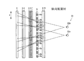
Moreover, there was a kind of motion to be provided with the crack peristome of (slit) shape and the barrier of light shielding part in the past, and can points out the stereoscopic display device of stereo-picture the beholder by configuration by beholder's one side at display panel.Figure 17 is in order to the vertical view of the principle of stereoscopic display device that known example is described.The formation of known stereoscopic display device 500 is described with reference to Figure 17.
Known stereoscopic display device 500 possesses as shown in figure 17: in order to the display panel (display panel) 501 of display image; Be configured in the Polarizer 502 by beholder's 510 1 sides of display panel 501; And be arranged on Polarizer 502 by the barrier layer 503 of beholder's 510 1 sides.
In addition, display panel 501 has glass substrate 501a.And, at display panel 501, be arranged alternately towards in fact with the pixel column 501b and the 501c of direction (direction vertical) extension of the line quadrature of left eye 510a that is connected beholder 510 and right eye 510b with the paper direction of Figure 17.Show the image L10 that beholder 510 left eye 510a will watch at this pixel column 501b, and show the image R10 that beholder 510 right eye 510b will watch at this pixel column 501c.
Be provided with at barrier layer 503: in order to cover from the light shielding part 503a of the light of display panel 501 ejaculations; And use so that the peristome 503b that the light that penetrates from display panel 501 penetrates.The pixel column 501b of this light shielding part 503a and peristome 503b and display panel 501 and 501c similarly, with towards being arranged alternately with the mode of direction (direction vertical) extension of the line quadrature of left eye 510a that is connected beholder 510 and right eye 510b in fact with the paper direction of Figure 17.And light shielding part 503a and peristome 503b and pixel column 501b and 501c by display panel 501 are constituted respectively organizes corresponding setting.
Secondly, the 3 D image display method of known stereoscopic display device 500 is described with reference to Figure 17.
In known stereoscopic display device 500, when the peristome 503b that beholder 510 sees through barrier layer 503 watches display panel 501, the image L10 that is presented at the pixel column 501b of display panel 501 can inject beholder 510 left eye 510a, and the image R10 that is presented at the pixel column 501c of display panel 501 can inject beholder 510 right eye 510b.Thus, beholder 510 can observe stereo-picture.
Yet, in known stereoscopic display device 500 shown in Figure 17, exist only to satisfy when for example vertically disposing stereoscopic display device 500 stereo-picture is offered beholder 510, and when landscape configuration stereoscopic display device 500 for example, be difficult to stereo-picture is offered beholder 510 problem.
No. 2857429 disclosed schemes of communique of above-mentioned Jap.P. also have identical problem.
Summary of the invention
The present invention is intended to solve aforementioned problems, and one object of the present invention is to provide a kind of reaching when landscape configuration all to can be the image display device that the beholder provides stereo-picture when vertically disposing.
For reaching above-mentioned purpose, the related image display device of one aspect of the invention possesses: in order to the display panel of display image; In order to the light source of rayed at display panel; In order to will be separated into light from the light that light source shone and have the 1st polarizing axis control device of the light of the 2nd polarizing axis with the 1st polarizing axis; In order to will be separated into light from the light that light source shone and have the 2nd polarizing axis control device of the light of the 4th polarizing axis with the 3rd polarizing axis; With display panel under the state of vertical configuration, penetrate by making light and having one in the light of the 2nd polarizing axis with the 1st polarizing axis, and provide stereo-picture, and, with display panel under the state of landscape configuration, penetrate by making light and having one in the light of the 4th polarizing axis, and stereo-picture is provided with the 3rd polarizing axis.
In image display device related aspect this, as mentioned above, the 1st polarizing axis control device and the 2nd polarizing axis control device are set, and with display panel under the state of vertical configuration, by one light with the 1st polarizing axis that separates from light source irradiation and by the 1st polarizing axis control device and the light with the 2nd polarizing axis penetrated, and to stereo-picture is provided; And with display panel under the state of landscape configuration, penetrate by making one light that separates from light source irradiation and by the 2nd polarizing axis control device and light with the 4th polarizing axis with the 3rd polarizing axis, and provide stereo-picture, under the situation of the both sides during towards vertical when configuration and towards landscape configuration with display panel, all can provide stereo-picture whereby.
Aspect above-mentioned in the related image display device, preferably, with display panel under the state of vertical configuration, in light by having the 1st polarizing axis and the light one with the 2nd polarizing axis, left eye is penetrated with image, right eye is penetrated with image, and stereo-picture is provided; With display panel under the state of landscape configuration, one in light by having the 3rd polarizing axis and the light with the 4th polarizing axis makes left eye penetrate with image, right eye is penetrated with image, and stereo-picture is provided.According to above formation, with display panel towards vertical when configuration and towards the both sides' of landscape configuration situation, all can easily provide stereo-picture for the beholder.
In the related image display device, preferably, the 1st polarizing axis control device comprises aspect above-mentioned: in order to will be from light-operated several the 1st polarisation control areas of making the light with the 1st polarizing axis that light source shone; And in order to will be from light-operated several the 2nd polarisation control areas of making light that light source shone with the 2nd polarizing axis; Several the 1st polarisation control areas and several the 2nd polarisation control areas under the state of vertical configuration, are configured to the stage shape at display panel.According to above formation, by several the 1st polarisation control areas and several the 2nd polarisation control areas that is configured in tilted direction, can make light and have one in the light of the 2nd polarizing axis with the 1st polarizing axis, under the state that disperses towards longitudinal direction and transverse direction approximate equality, penetrating, therefore can be with the reduction of the resolution of the image of display panel towards longitudinal direction and transverse direction dispersion.Thus, can be the beholder provides image deterioration less stereo-picture.
Comprise in the image display device of the 1st polarisation control area and the 2nd polarisation control area at aforementioned the 1st polarizing axis control device, preferably, display panel comprises in order to the some spots zone of 3 primary colors of display light (dot region); The 1st polarisation control area of the 1st polarizing axis control device and the 2nd polarisation control area, each point that is configured in display panel respectively is regional.Constitute according to this,, can under the state of sectionalization, make the image of display panel inject beholder's eyes by being arranged on the 1st polarisation control area and the 2nd polarisation control area in each some zone.Thus, can be the beholder image deterioration stereo-picture still less is provided.
In the related image display device, preferably, the 1st polarizing axis control device comprises polarizer aspect above-mentioned.When so using polarizer, can be easily will be separated into light from the light that light source shone and have the light of the 2nd polarizing axis with the 1st polarizing axis.
In the related image display device, preferably, the 2nd polarizing axis control device comprises aspect above-mentioned: in order to will be from light-operated several the 3rd polarisation control areas of making the light with the 3rd polarizing axis that light source shone; And in order to will be from light-operated several the 4th polarisation control areas of making light that light source shone with the 4th polarizing axis; The 3rd polarisation control area and the 4th polarisation control area with display panel under the state of landscape configuration, towards extending with laterally vertical direction in fact, and with horizontal alternate configurations.According to this formation, with display panel under the state of landscape configuration, by towards the 3rd polarisation control area and the 4th polarisation control area of extending with the vertical direction of the direction of the right and left eyes that is connected the beholder in fact, can easily make light and have one in the light of the 4th polarizing axis and advance towards beholder's eyes with the 3rd polarizing axis, thereby can be easily with display panel under the state of landscape configuration, stereo-picture is provided.
With aforesaid display panel under the state of landscape configuration, comprise in the image display device of the 3rd polarisation control area and the 4th polarisation control area at aforementioned the 2nd polarizing axis control device, preferably, display panel comprises 3 some zones in order to 3 primary colors of difference display light, and its horizontal length of watching the 3rd polarisation control area and the 4th polarisation control area of the 2nd polarizing axis control device along connection is set in the mode of the horizontal length in corresponding point zone in fact; In order to 3 some zones of 3 primary colors of the light that shows display panel respectively, to be adjacent to towards disposing with the mode of laterally vertical direction in fact.According to this formation, can be with towards the 3rd polarisation control area and the 4th polarisation control area that are provided with the vertically extending mode of the direction of the right and left eyes that is connected the beholder in fact, dispose 3 some zones of 3 primary colors of corresponding light respectively, therefore, can provide image deterioration less stereo-picture for the beholder.
Comprise in the image display device of the 3rd polarisation control area and the 4th polarisation control area at aforementioned the 2nd polarizing axis control device, preferably, the 2nd polarizing axis control device comprises the 1st polarisation control liquid crystal panel with the 3rd polarisation control area and the 4th polarisation control area, the 3rd polarisation control area and the 4th polarisation control area at the 1st polarisation control liquid crystal panel, with towards the mode of extending with the 3rd polarisation control area and the 4th polarisation control area equidirectional, be formed with respectively in order to voltage is applied to the electrode of liquid crystal.According to this formation, use the electrode of 1 polarisation control liquid crystal panel, voltage can be applied to the liquid crystal of the 3rd polarisation control area and the 4th polarisation control area, therefore can pass through the voltage application state of control liquid crystal, and the 3rd polarisation control area and the 4th polarisation control area are changed easily.Thus, only towards landscape configuration the time, can carry out polarisation control.
Aspect above-mentioned in the related image display device, preferably, also has the 3rd polarizing axis control device, its with display panel under the state of vertical configuration, the light-operated light of making that will have the 1st polarizing axis with the 5th polarizing axis, and the light-operated light with the 6th polarizing axis of making that will have the 2nd polarizing axis, under the state of landscape configuration, the light that makes the light with the 1st polarizing axis and have the 2nd polarizing axis penetrates in the mode of not controlling polarizing axis.According to this formation, by the 3rd polarizing axis control device, only the predetermined reference edge of display panel during towards vertical configuration, can carried out polarisation control, and the predetermined reference edge of display panel during towards landscape configuration, can not carried out polarisation control.
In the image display device that possesses aforementioned the 3rd polarizing axis control device, preferably, the 3rd polarizing axis control device comprises the 2nd polarisation control liquid crystal panel, the 2nd polarisation control liquid crystal panel is changeable: will have the light-operated light with the 5th polarizing axis of making of the 1st polarizing axis, and will have light-operated the 1st state of making the light with the 6th polarizing axis of the 2nd polarizing axis; And make light and have the 2nd state that the light of the 2nd polarizing axis penetrates in the mode of not controlling polarizing axis with aforementioned the 1st polarizing axis.According to this formation, by the 2nd polarisation control liquid crystal panel, can be with the predetermined reference edge of display panel towards the situation of vertical configuration, and with the predetermined reference edge of display panel situation towards landscape configuration, switch aforementioned the 1st state and the 2nd state, therefore can be easily according to having or not that the configuration status switching polarisation of display panel is controlled.
Comprise in the image display device of the 2nd polarisation control liquid crystal panel at aforementioned the 3rd polarizing axis control device, preferably, the 2nd polarisation control liquid crystal panel passes through control voltage application state, and switches the 1st state and the 2nd state.According to this formation, by the 2nd polarisation control liquid crystal panel, can easily switch the 1st state and the 2nd state, therefore can be more easily according to having or not that the configuration status switching polarisation of display panel is controlled.
In the image display device that possesses aforementioned the 3rd polarizing axis control device, preferably, the 3rd polarizing axis control device is disposed at the subtend of aforementioned light source with respect to the 1st polarizing axis control device.Constitute according to this, the light with the 1st polarizing axis easily can be controlled to the light with the 5th polarizing axis, and the light with the 2nd polarizing axis easily can be controlled to the light with the 6th polarizing axis.
In the image display device that possesses aforementioned the 3rd polarizing axis control device, preferably, also possesses the 1st Polarizer, the 1st Polarizer is disposed at the subtend of aforementioned light source with respect to the 3rd polarizing axis control device, and in order to cover one in light of being controlled by the 3rd polarizing axis control device with the 5th polarizing axis and the light with the 6th polarizing axis.Constitute according to this, can easily cover light and have one in the light of the 6th polarizing axis, therefore can easily only make light and have one in the light of the 6th polarizing axis and penetrate with the 5th polarizing axis with the 5th polarizing axis.
In the related image display device, preferably, the 1st polarizing axis control device and the 2nd polarizing axis control device dispose in the mode that clips display panel aspect above-mentioned.According to this formation, for example with in the situation of configuration the 2nd polarizing axis control device between display panel and the 1st polarizing axis control device compare, can dwindle the interval between display panel and the 1st polarizing axis control device, but therefore the decreased distance display panel suitably view and admire distance.Thus, when image display device involved in the present invention being used at the less mobile phone of display panel etc., the distance (suitably viewing and admiring distance) that can dwindle the eyes from display panel to the beholder therefore can be seen the stereo-picture of display panel easily clearly.
Aspect above-mentioned in the related image display device, preferably, also possesses the 2nd Polarizer, it is configured between the 2nd polarizing axis control device and the display panel, and in order to cover one in light with the 3rd polarizing axis that is separated by the 2nd polarizing axis control device and the light with the 4th polarizing axis.Constitute according to this, can easily make and cover light and have one in the light of the 4th polarizing axis, therefore can easily only make light and have one in the light of the 4th polarizing axis and advance towards beholder's eyes with the 3rd polarizing axis with the 3rd polarizing axis.
In the related image display device, preferably, also possess the 3rd Polarizer aspect above-mentioned, it is configured between light source and the 2nd polarizing axis control device, and with so that from the light that light source shone, only have the light of predetermined polarizing axis and penetrate.According to this formation, can be by the 1st polarizing axis control device easily with light from light source shone, be separated into light and have the light of the 2nd polarizing axis with the 1st polarizing axis, and by the 2nd polarizing axis control device, can easily be separated into light and have the light of the 4th polarizing axis with the 3rd polarizing axis.
Aspect above-mentioned in the related image display device, preferably, also possess in order to will having the light-operated light of making of the 1st polarizing axis, and will have light-operated the 3rd polarizing axis control device of making light of the 2nd polarizing axis with the 6th polarizing axis with the 5th polarizing axis; The 2nd polarizing axis control device is changeable: make the light with the 3rd polarizing axis and have situations about penetrating in the light of the 4th polarizing axis; And make light and have the situation that the both sides of the light of the 4th polarizing axis penetrate with the 3rd polarizing axis; And the 3rd polarizing axis control device is changeable: make the light with the 5th polarizing axis and have situations about penetrating in the light of the 6th polarizing axis; And make light and have the situation that the both sides of the light of the 6th polarizing axis penetrate with the 5th polarizing axis, the 2nd polarizing axis control device makes the light with the 3rd polarizing axis and has both sides' ejaculation of the light of the 4th polarizing axis, and the 3rd polarizing axis control device makes the light with the 5th polarizing axis and has both sides' ejaculation of the light of the 6th polarizing axis, provides plane picture for aforementioned beholder whereby.According to this formation, by the 2nd polarizing axis control device is switched to: make light and have situations about penetrating in the light of the 4th polarizing axis with the 3rd polarizing axis, and the both sides that make the light with the 3rd polarizing axis and have the light of the 4th polarizing axis penetrate, and the 3rd polarizing axis control device is switched to: to make light and have situations about penetrating in the light of the 6th polarizing axis with the 5th polarizing axis, and the both sides that make the light with the 5th polarizing axis and have the light of the 6th polarizing axis penetrate, thereby can utilize 1 image display device to provide stereo-picture and two kinds of images of plane picture for the beholder.
Description of drawings
Fig. 1 is the exploded perspective view of the related image display device of demonstration one embodiment of the present of invention.
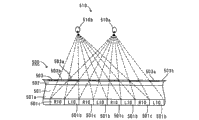
Fig. 2 shows that when the display panel that one embodiment of the present of invention shown in Figure 1 are related vertically disposes the beholder watches the synoptic diagram of display panel under the state of stereo-picture from the top.
Fig. 3 shows that when the display panel landscape configuration that one embodiment of the present of invention shown in Figure 1 are related the beholder watches the synoptic diagram of display panel under the state of stereo-picture from the top.
Fig. 4 is the horizontal part enlarged drawing with liquid crystal panel that shows that one embodiment of the present of invention shown in Figure 1 are related.
Fig. 5 is the part enlarged drawing of the display panel that shows the image display device that one embodiment of the present of invention shown in Figure 1 are the related display panel when vertically disposing.
Fig. 6 is the part enlarged drawing of the display panel when showing the display panel landscape configuration of the image display device that one embodiment of the present of invention shown in Figure 1 are related.
Fig. 7 is the part enlarged drawing of the polarizer of the related image display device of one embodiment of the present of invention shown in Figure 1.
Fig. 8 is the synoptic diagram in order to the 3 D image display method of the explanation display panel that one embodiment of the present of invention shown in Figure 1 are related when vertically disposing.
Fig. 9 is the synoptic diagram of the 3 D image display method during in order to explanation display panel landscape configuration that one embodiment of the present of invention shown in Figure 1 are related.
Figure 10 is that the beholder watches the synoptic diagram of display panel 5 under the state of display plane image when the display panel that one embodiment of the present of invention shown in Figure 1 are related 5 vertically disposes from the top.
Figure 11 is when vertically disposing in order to explanation display panel that one embodiment of the present of invention shown in Figure 1 are related 5 and the synoptic diagram of the plane picture display packing during landscape configuration.
Figure 12 is that the beholder watches the synoptic diagram of display panel 5 under the state of display plane image when the display panel that one embodiment of the present of invention shown in Figure 1 are related 5 landscape configuration from the top.
Figure 13 is the synoptic diagram of the effect of the image display device that is used for illustrating that one embodiment of the present of invention shown in Figure 1 are related.
Figure 14 is the synoptic diagram of the effect of the image display device that is used for illustrating that one embodiment of the present of invention shown in Figure 1 are related.
Figure 15 is the synoptic diagram of the display panel of the related image display device of the variation of demonstration one embodiment of the present of invention shown in Figure 1.
Figure 16 is the synoptic diagram of the polarizer of the related image display device of the variation of demonstration one embodiment of the present of invention shown in Figure 1.
Figure 17 is the vertical view in order to the principle of the stereoscopic display device that a known example is described.
Symbol description
1 image display device
2 is backlight
3,6,7,10,502 Polarizers
The liquid crystal panel of 4 horizontal usefulness
4a, 4b, 8a, 8b, 18a, 18b polarisation control area
The 4c electrode
5,15,501 display panels
5a to 5g point zone
8,18 polarizers
The liquid crystal panel of 9 vertical usefulness
20,510 beholders
20a, 510a left eye
20b, 510b right eye
51 reference edges
500 stereoscopic display devices
The 501a glass substrate
501b, 501c pixel column
503 barrier layers
The 503a light shielding part
The 503b peristome
L1, L2, L3 left eye image
R1, R2, R3 right eye image
The R10 image
S1, S2 plane picture
Embodiment
Followingly concrete enforcement of the present invention is described with reference to accompanying drawing.
The formation of the related image display device of one embodiment of the present of invention 1 at first, is described referring to figs. 1 through Fig. 7.
As shown in Figure 1, the related image display device 1 of one embodiment of the present of invention possesses: backlight 2; Be configured in the Polarizer 3 of backlight 2 light exit side; Be disposed at the polarisation control liquid crystal panel 4 (to call (the laterally liquid crystal panel of usefulness) in the following text) of horizontal usefulness of the light exit side of Polarizer 3; Be configured in the light exit side of the liquid crystal panel 4 of horizontal usefulness, and by the display panel that display panels constituted 5, the Polarizer 6 and 7 that disposes in the mode of double team display panel 5 in order to display image; Be configured in the polarizer 8 of the light exit side of Polarizer 7; Be disposed at the polarisation control liquid crystal panel 9 (to call (the vertically liquid crystal panel 9 of usefulness) in the following text) of vertical usefulness of the light exit side of polarizer 8; And be configured in the Polarizer 10 of light exit side of the liquid crystal panel 9 of vertical usefulness.Backlight 2 is an example of (light source) of the present invention, and Polarizer 3 is an example of (the 3rd Polarizer) of the present invention.And laterally the liquid crystal panel 4 of usefulness is an example of (the 2nd polarizing axis control device) of the present invention and (the 1st polarisation control liquid crystal panel), and Polarizer 6 is examples of (the 2nd Polarizer) of the present invention.And polarizer 8 is examples of (the 1st polarizing axis control device) of the present invention.Vertically the liquid crystal panel 9 of usefulness is an example of (the 3rd polarizing axis control device) of the present invention and (the 2nd polarisation control liquid crystal panel).Polarizer 10 is examples of (the 1st Polarizer) of the present invention.In the present embodiment, with display panel 5 vertically configuration mean that the reference edge 51 (with reference to Fig. 1) of display panel 5 watches the state that is configured in vertical direction (the Y direction of Fig. 1) from beholder 20 angle, display panel 5 landscape configuration are meaned the reference edge 51 of display panel 5 is watched the state that is configured in horizontal direction (directions X of Fig. 1) from beholder 20 angle.Moreover Y direction (vertical direction) is an example of (the 1st direction) of the present invention, and directions X (horizontal direction) is an example of (the 2nd direction) of the present invention.
Moreover as shown in Figure 4, laterally the liquid crystal panel 4 of usefulness has polarisation control area 4a and polarisation control area 4b.Polarisation control area 4a is an example of (the 3rd polarisation control area) of the present invention, and polarisation control area 4b is an example of (the 4th polarisation control area) of the present invention.Polarisation control area 4a and polarisation control area 4b are with display panel 5 (with reference to Fig. 1) landscape configuration the time (situation of Fig. 3 and Fig. 4), with towards disposing with mode that the vertical in fact direction (Y direction) of the tie line of beholder's 20 (with reference to Fig. 3) left eye 20a and right eye 20b is extended.Be respectively arranged with the electrode 4c that extends towards the Y direction at polarisation control area 4a and polarisation control area 4b.Thus, can use electrode 4c to the polarisation control area 4a of the liquid crystal panel 4 that is positioned at horizontal usefulness and the liquid crystal applied voltages of polarisation control area 4b, therefore by the state of control, the polarisation state of a control of polarisation control area 4a and polarisation control area 4b is changed to liquid crystal applied voltages.Thus, only when landscape configuration, can utilize the polarisation control of the liquid crystal panel 4 of horizontal usefulness.Polarisation control area 4a and polarisation control area 4b watch the have horizontal direction polarizing axis of (about 0 °) from beholder 20 angle.And laterally the polarisation control area 4a of the liquid crystal panel 4 of usefulness has the function that the polarizing axis that makes the light that is penetrated is changed to and laterally the polarizing axis of the horizontal direction (about 0 °) of the polarisation control area 4a of the liquid crystal panel 4 of usefulness is the polarizing axis of line symmetry.Particularly, laterally the liquid crystal panel 4 of usefulness has the function of the light of being injected being given the phase differential of λ/2, therefore with respect to the polarizing axis of the horizontal direction (about 0 °) of the liquid crystal panel 4 of horizontal usefulness, the polarizing axis of light by the horizontal direction (about 0 °) of the liquid crystal panel 4 of horizontal usefulness that for example has the polarizing axis of angle [alpha] is changed to the light of the polarizing axis with angle-α and penetrates.In addition, in the present embodiment, as described later, the liquid crystal panel 9 of polarizer 8 and vertical usefulness also has same function.Laterally the polarisation control area 4a of the liquid crystal panel 4 of usefulness and polarisation control area 4b apply state (ON state) to have a polarizing axis of horizontal direction of making (about 0 °) invalid by being made as voltage, and the function that light with predetermined polarizing axis is penetrated, and by being made as voltage is non-to be applied state (OFF state) to have a polarizing axis of horizontal direction of making (about 0 °) effective, and to be the function that polarizing axis that the line symmetrical manner makes light changes with this polarizing axis.With display panel 5 (with reference to Fig. 1) landscape configuration the time (situation of Fig. 3 and Fig. 4), polarisation control area 4a becomes voltage and applies state (ON state), and polarisation control area 4b becomes the non-state (OFF state) that applies of voltage.Polarizer 6 is watched from beholder 20 angle having about 135 ° polarizing axis as shown in Figure 1, therefore has from beholder 20 angle to watch the function that light with about 135 ° polarizing axis is penetrated.
Moreover display panel 5 has makes the light of injecting change the function that penetrates under about 90 ° state at polarizing axis.Display panel 5 has as shown in Figure 5: by the plurality of pixels zone 5d that is constituted in order to 3 somes zone 5a to 5c of 3 primary colors of the light that shows redness (R), green (G), blue (B) respectively; And by the plurality of pixels zone 5h that is constituted in order to 3 somes zone 5e to 5g of 3 primary colors of display light respectively.
At this, in the present embodiment, when display panel 5 is vertically disposed, put regional 5a to 5c and put the shown left eye of regional 5e to 5g is configured to a stair-stepping example with image R1 with image L1 and right eye staggered clathrate (stepped).Particularly, at each point shown in Figure 5 zone 5a to 5c and put among the regional 5e to 5g, right eye with the viewing area of image R1 with shown in shade (oblique line) zone, left eye with the viewing area of image L1 with shown in the non-hatched area of not executing shade (oblique line).As shown in Figure 5, the left eye that is positioned at the shadow region with the regional 5a to 5c of point of RGB and put the continuous mode of regional 5e to 5g, is presented at the tilted direction (the A direction of Fig. 5) that intersects with the both sides of directions X and Y direction with image L1.And the right eye that is positioned at unblanketed non-hatched area uses image R1 also in the continuous mode in some zone of RGB, is presented at tilted direction (the A direction of Fig. 5).Left eye uses image R1 with the regional continuous mode of the point of RGB, the direction that Alternation Display is intersected at the tilted direction (the A direction of Fig. 5) with extension with image L1 and right eye.
In the present embodiment, during with display panel 5 landscape configuration, as shown in Figure 6, the regional 5a to 5c of point of 3 primary colors (RGB) of corresponding light and put regional 5e to 5g is with towards disposing with the mode of beholder's 20 (with reference to Fig. 3) left eye 20a direction (longitudinal direction) (Y direction) extension vertical with the tie line of right eye 20b in fact.In addition, prolonging with a regional 5a to 5c and putting beholder's 20 (with reference to Fig. 3) the left eye 20a of regional 5e to 5g and the length of the direction (transverse direction) (directions X) of the tie line of right eye 20b, be arranged to corresponding with the length of prolonging with the direction (transverse direction) (directions X) of the tie line of the beholder's 20 of the polarisation control area 4a of the liquid crystal panel 4 (with reference to Fig. 4) of horizontal usefulness and polarisation control area 4b (with reference to Fig. 4) left eye 20a and right eye 20b.Under the situation of landscape configuration shown in Figure 6, with the left eye shown in shade (oblique line) zone with image L2, and show in the mode that is extended with the regional 5a to 5c of point of RGB towards longitudinal direction (Y direction) continuously and puts regional 5e to 5g separately with image R2 with the right eye shown in the unblanketed non-hatched area.And, under the situation of landscape configuration shown in Figure 6, use image R2 towards transverse direction (directions X) Alternation Display with image L2 and right eye towards the left eye that longitudinal direction (Y direction) extends.And, the zone (shadow region) of demonstration left eye usefulness image L2 as shown in Figure 3, on the polarisation control area 4b that is configured in the liquid crystal panel 4 that links horizontal usefulness and the line of beholder 20 left eye 20a, and be configured on the polarisation control area 4a of liquid crystal panel 4 of the horizontal usefulness of binding and beholder's 20 the line of right eye 20b.In addition, show the zone (non-hatched area) of right eye with image R2, on the polarisation control area 4a that is configured in the liquid crystal panel 4 that links horizontal usefulness and the line of beholder 20 left eye 20a, and be configured on the polarisation control area 4b of liquid crystal panel 4 of the horizontal usefulness of binding and beholder's 20 the line of right eye 20b.
Moreover Polarizer 7 is watched from beholder's 20 sides having about 135 ° polarizing axis as shown in Figure 1, therefore has only to make the function of watching light with about 135 ° polarizing axis to penetrate from beholder's 20 sides.And polarizer 8 comprises several polarisation control area 8a and polarisation control area 8b as shown in Figure 7.Polarisation control area 8a is an example of (the 1st polarisation control area) of the present invention, and polarisation control area 8b is an example of (the 2nd polarisation control area) of the present invention.Polarisation control area 8a as shown in Figure 2, be configured in and link on the left eye show display panel 5 the line, and be configured on the zone that links the right eye usefulness image R1 that shows display panel 5 and beholder's 20 the line of left eye 20a with the zone of image L1 and beholder 20 right eye 20b.Polarisation control area 8b is configured in and links on the left eye show display panel 5 line with the zone of image L1 and beholder 20 left eye 20a, and is configured on the zone that links the right eye usefulness image R1 that shows display panel 5 and beholder's 20 the line of right eye 20b.And, as shown in Figure 7, polarisation control area 8a and polarisation control area 8b have vertical configuration shown in Figure 5 state display panel 5 the regional 5a to 5c of point and put that regional 5e to 5g is pairing to be essentially rectangular shape.With display panel 5 (with reference to Fig. 5) when vertically disposing, with the regional 5a to 5c of point of display panel 5 and put regional 5e to 5g similarly, the long side direction of polarisation control area 8a and polarisation control area 8b is to dispose towards the mode with the vertical in fact direction (Y direction) of the tie line of beholder's 20 (with reference to Fig. 2) left eye 20a and right eye 20b (with reference to Fig. 2).The polarisation control area 8a of polarizer 8 and polarisation control area 8b have the polarizing axis that makes the light that is penetrated and are changed to the function that is the polarizing axis of line symmetry with the polarizing axis of polarizer 8.
Moreover in the present embodiment, the polarisation control area 8a of polarizer 8 and polarisation control area 8b such as Fig. 5 and shown in Figure 7 are configured to staggered clathrate with image L1 and right eye with the mode of the viewing area of image R1 with the left eye of corresponding display panel 5.Moreover in the present embodiment, the polarisation control area 8a of polarizer 8 and 8b are configured to staggered clathrate and are a stepped example.And for example shown in Figure 7, polarisation control area 8a watches from beholder 20 (with reference to Fig. 2) side has about 75 ° polarizing axis, and polarisation control area 8b watches from beholder's 20 sides has about 15 ° polarizing axis.
In addition, vertically the liquid crystal panel 9 of usefulness as shown in Figure 1, watch from beholder's 20 sides having about 165 ° polarizing axis, vertically the liquid crystal panel 9 of usefulness has the polarizing axis that makes the light that is penetrated and is changed to the function that is the polarizing axis of line symmetry with vertical about 165 ° polarizing axis of the liquid crystal panel 9 of usefulness.Vertically the liquid crystal panel 9 of usefulness has by being made as voltage and applies state (ON state) and make the invalid function of about 165 ° polarizing axis, and has by being made as the non-state (OFF state) that applies of voltage and have and make the effective function of about 165 ° polarizing axis.Polarizer 10 is watched from beholder's 20 sides has about 135 ° polarizing axis.The angle that the polarizing axis of the polarizing axis of the light that Polarizer 10 will be injected and Polarizer 10 intersects is made as θ, with light quantity (amplitude of light) when being made as C, have and the light of being injected is changed to from beholder's 20 sides watch light, and be changed to and have C * (cos θ) with about 135 ° polarizing axis
2Light quantity and the function that penetrates that makes.
Stereo-picture display mode when vertically disposing
In Fig. 8, dotted line shows that Polarizer 3,6,7,10, the laterally angle of the polarizing axis of the liquid crystal panel 9 of liquid crystal panel 4, polarizer 8 and vertical usefulness of usefulness, and arrow show the angle of the polarizing axis that penetrates light.Secondly, with reference to Fig. 2, Fig. 4 and Fig. 8, the 3 D image display method when vertical configuration of the display panel 5 that one embodiment of the present of invention relate to be described.
At first, from the light of 2 (with reference to Fig. 2) backlight irradiation as shown in Figure 8, only make from beholder 20 (with reference to Fig. 2) side by Polarizer 3 and to watch light to penetrate with about 135 ° polarizing axis.And, watch light from beholder's 20 sides with about 135 ° polarizing axis, penetrate the polarisation control area 4a and the polarisation control area 4b of the liquid crystal panel 4 of horizontal usefulness.At this moment, laterally the polarisation control area 4a of the liquid crystal panel 4 of usefulness and polarisation control area 4b be by being applied to voltage electrode 4c (with reference to Fig. 4), and be controlled at the ON state.Therefore, laterally the polarizing axis of the polarisation control area 4a of the liquid crystal panel 4 of usefulness and polarisation control area 4b become invalid.Thus, injecting the polarisation control area 4a of liquid crystal panel 4 of horizontal usefulness and the light of polarisation control area 4b penetrates under the state that polarizing axis can not change.Thereafter, the light that penetrates from the liquid crystal panel 4 of horizontal usefulness penetrates from beholder's 20 sides and watches the Polarizer 6 with about 135 ° of polarizing axis.Moreover, penetrate the light of Polarizer 6 and inject the regional 5a to 5c of point of display panel 5 and put regional 5e to 5g.At this moment, as shown in Figure 5, at a regional 5a to 5c and put shade (oblique line) zone among the regional 5e to 5g, show left eye with image L1 (with reference to Fig. 2), at a regional 5a to 5c and put non-hatched area among the regional 5e to 5g, show right eye with image R1 (with reference to Fig. 2).The light of injecting display panel 5 changes at polarizing axis by display panel 5 under 90 ° the state and penetrates as shown in Figure 8.That is, the light that penetrates display panel 5 is watching polarizing axis to change ejaculation under about 45 ° state from beholder 20 (with reference to Fig. 2) side.And the light that penetrates from display panel 5 penetrates from beholder's 20 sides watches the Polarizer 7 with about 45 ° polarizing axis.The light that penetrates Polarizer 7 is injected the polarisation control area 8a or the polarisation control area 8b of polarizer 8.
Moreover, in the present embodiment, the light of injecting polarizer 8 is watched from beholder 20 (with reference to Fig. 2) side has about 45 ° polarizing axis, therefore as shown in Figure 8, inject the light of the polarisation control area 8a of polarizer 8, the about 75 ° polarizing axis that is changed to the polarisation control area 8a of polarizer 8 is the polarizing axis of line symmetry, and is penetrated.That is, the light that penetrates from polarisation control area 8a is watched from beholder's 20 sides and is had about 105 ° polarizing axis.And, from the light that the polarisation control area 8a of polarizer 8 penetrates, be changed to vertical about 165 ° polarizing axis of the liquid crystal panel 9 of usefulness and be the polarizing axis of line symmetry, and penetrated.That is, the light that penetrates from the liquid crystal panel 9 of vertical usefulness is watched from beholder's 20 sides and is had about 45 ° polarizing axis.Thereafter, the light that penetrates from the liquid crystal panel 9 of vertical usefulness is by watch 10 shadings of Polarizer with about 135 ° polarizing axis from beholder's 20 sides.At this moment, the polarisation control area 8a of polarizer 8 is configured in and links on the left eye show display panel 5 line with the zone of image L1 and beholder 20 right eye 20b as shown in Figure 2, so can suppress left eye is injected beholder 20 with image L1 right eye 20b.And the polarisation control area 8a of polarizer 8 is configured in and links on the right eye show display panel 5 line with the zone of image R1 and beholder 20 left eye 20a, so can suppress right eye is injected beholder 20 with image R1 left eye 20a.
On the other hand, inject polarizer 8 polarisation control area 8b light as shown in Figure 8, the about 15 ° polarizing axis that is changed to the polarisation control area 8b of polarizer 8 is the polarizing axis of line symmetry, and is penetrated.That is, the light that penetrates from polarisation control area 8b is watched from beholder's 20 sides and is had about 165 ° polarizing axis.And, from the light that the polarisation control area 8b of polarizer 8 penetrates, be changed to vertical about 165 ° polarizing axis of the liquid crystal panel 9 of usefulness and be the polarizing axis of line symmetry, and penetrated.At this moment, the angle of the polarizing axis of the light that penetrates from the polarisation control area 8b of polarizer 8 is identical with the angle of the vertical polarizing axis of the liquid crystal panel 9 of usefulness, so injects the light of the liquid crystal panel 9 of vertical usefulness, penetrates under about 165 ° of unchanged states at polarizing axis.Thereafter, the light that penetrates from the liquid crystal panel 9 of vertical usefulness is watched from beholder 20 (with reference to Fig. 2) side and is changed to about 135 ° polarizing axis, and for example with light quantity (amplitude of light) when being made as D, has D * (cos θ 1) being changed to
2Penetrate from Polarizer 10 under the state of the light of the light quantity (amplitude of light) of (about 165 °-Yue 135 °=about 30 ° of θ 1=).At this moment, the polarisation control area 8b of polarizer 8 as shown in Figure 2, be configured in link the left eye show display panel 5 with the zone of image L1, and the line of beholder 20 left eye 20a on, therefore left eye can be injected beholder 20 left eye 20a with image L1.And, the polarisation control area 8b of polarizer 8 be configured in link the right eye show display panel 5 with the zone of image R1, and the line of beholder 20 right eye 20b on, therefore right eye can be injected beholder 20 right eye 20b with image L1.
As mentioned above, when vertical configuration, by left eye is injected beholder 20 left eye 20a and right eye 20b with image L1 and right eye respectively with image R1, so beholder 20 can watch stereo-picture.
Stereo-picture display mode during landscape configuration
Then, with reference to Fig. 4 and Fig. 9, the 3 D image display method the when landscape configuration of the display panel 5 that one embodiment of the present of invention relate to is described.
At first, from the light of 2 (with reference to Fig. 3) backlight irradiation as shown in Figure 9, only make from beholder 20 (with reference to Fig. 3) side by Polarizer 3 and to watch light to penetrate with about 135 ° polarizing axis.And, when landscape configuration, compare during with vertical configuration, though polarizing axis half-twist separately, in the present embodiment, in order to oversimplify, even when landscape configuration, the angle of the polarizing axis when also directly adopting vertically configuration describes.And watch light with about 135 ° polarizing axis from beholder's 20 sides, penetrate the polarisation control area 4a and the polarisation control area 4b of the liquid crystal panel 4 of horizontal usefulness.
Moreover when landscape configuration, laterally the polarisation control area 4a of the liquid crystal panel 4 of usefulness is controlled to the OFF state that voltage is not applied to electrode 4c (with reference to Fig. 4).Therefore, laterally the polarizing axis of the horizontal direction (about 0 °) of the polarisation control area 4a of the liquid crystal panel 4 of usefulness becomes effectively.Thus, inject the light of polarisation control area 4a of the liquid crystal panel 4 of horizontal usefulness, be changed to the polarizing axis of the horizontal horizontal direction (about 0 °) of the polarisation control area 4a of the liquid crystal panel 4 of usefulness axisymmetricly polarizing axis and penetrate.That is the light that penetrates from polarisation control area 4a is watched from beholder's 20 sides has about 45 ° polarizing axis.And the light that penetrates from the polarisation control area 4a of the liquid crystal panel 4 of horizontal usefulness is by watching the Polarizer 6 with about 135 ° polarizing axis to be covered from beholder's 20 sides.At this moment, as shown in Figure 3, on the line of the polarisation control area 4a of the liquid crystal panel 4 that links horizontal usefulness and beholder 20 left eye 20a, dispose the right eye that shows display panel 5 zone, so can suppress right eye is injected beholder 20 with image R2 left eye 20a with image R2.Moreover, on the line of the polarisation control area 4a of the liquid crystal panel 4 that links horizontal usefulness and beholder 20 right eye 20b, dispose the left eye that shows display panel 5 zone, so can suppress left eye is injected beholder 20 with image L2 right eye 20b with image L2.
On the other hand, laterally the polarisation control area 4b of the liquid crystal panel 4 of usefulness is controlled to the ON state that voltage is applied to electrode 4c (with reference to Fig. 4) when vertically disposing.Therefore, laterally the polarizing axis of the polarisation control area 4b of the liquid crystal panel 4 of usefulness become invalid.Therefore, inject horizontal usefulness liquid crystal panel 4 polarisation control area 4b light as shown in Figure 9, under the state that polarizing axis can not change, penetrate.That is,, watch light with about 135 ° polarizing axis from beholder 20 (with reference to Fig. 3) side from the light that the polarisation control area 4b of the liquid crystal panel 4 of horizontal usefulness penetrates.
Moreover the light from the polarisation control area 4b of the liquid crystal panel 4 of horizontal usefulness penetrates penetrates from beholder 20 (with reference to Fig. 3) side and watches the Polarizer 6 with about 135 ° polarizing axis.And inject the regional 5a to 5c of point of display panel and put regional 5e to 5g from the light that Polarizer 6 penetrates.The light of injecting display panel 5 penetrates under the state of 90 ° of polarizing axis variations by display panel 5.That is, the light that penetrates display panel 5 is being watched from beholder's 20 sides, and polarizing axis changes 45 ° state ejaculation down.And the light that penetrates from display panel 5 penetrates from beholder's 20 sides watches the Polarizer 7 with about 45 ° polarizing axis.The light that penetrates Polarizer 7 is injected the polarisation control area 8a or the polarisation control area 8b of polarizer 8.
In the present embodiment, the light of injecting polarizer 8 is watched from beholder 20 (with reference to Fig. 3) side has about 45 ° polarizing axis, therefore inject the light of the polarisation control area 4a of polarizer 8, the about 75 ° polarizing axis that is changed to the polarisation control area 8a of polarizer 8 is the polarizing axis of line symmetry, and is penetrated.That is, the light that penetrates from polarisation control area 8a is watched from beholder's 20 sides and is had about 105 ° polarizing axis.And vertically the liquid crystal panel 9 of usefulness is controlled to the ON state, and it is invalid that liquid crystal panel 9 polarizing axis of therefore vertical usefulness become.Thus, inject the light of the liquid crystal panel 9 of vertical usefulness, the liquid crystal panel 9 from vertical usefulness under the state that polarizing axis can not change penetrates.That is the light that penetrates from the liquid crystal panel 9 of vertical usefulness is watched from beholder's 20 sides has about 105 ° polarizing axis.After, the light that penetrates from the liquid crystal panel 9 of vertical usefulness is watched from beholder's 20 sides and is changed to about 135 ° polarizing axis, and for example with light quantity (amplitude of light) when being made as E, has E * (cos θ 2) being changed to
2Penetrate from Polarizer 10 under the state of the light of the light quantity (amplitude of light) of (about 135 °-Yue 105 °=about 30 ° of θ 2=).At this moment, as shown in Figure 3, on the line of the polarisation control area 4b of the liquid crystal panel 4 that links horizontal usefulness and beholder 20 left eye 20a, dispose the left eye that shows display panel 5 zone, so left eye can be injected beholder 20 left eye 20a with image L2 with image L2.Moreover, on the line of the polarisation control area 4b of the liquid crystal panel 4 that links horizontal usefulness and beholder 20 right eye 20b, dispose the right eye that shows display panel 5 zone, so right eye can be injected beholder 20 right eye 20b with image R2 with image R2.
On the other hand, inject polarizer 8 polarisation control area 8b light as shown in Figure 9, the about 15 ° polarizing axis that is changed to the polarisation control area 8b of polarizer 8 is the polarizing axis of line symmetry, and is penetrated.That is, the light that penetrates from polarisation control area 8b is watched from beholder 20 (with reference to Fig. 3) side and is had about 165 ° polarizing axis.And vertically the liquid crystal panel 9 of usefulness is controlled so as to the ON state, and it is invalid that the polarizing axis of the liquid crystal panel 9 of therefore vertical usefulness becomes.Thus, the light liquid crystal panel 9 from vertical usefulness under the state that polarizing axis can not change that penetrates from the liquid crystal panel 9 of vertical usefulness penetrates.That is, the light that penetrates from the liquid crystal panel 9 of vertical usefulness is watched from beholder's 20 sides having about 165 ° polarizing axis.After, the light that penetrates from the liquid crystal panel 9 of vertical usefulness is watched from beholder's 20 sides and is changed to about 135 ° polarizing axis, and for example with light quantity (amplitude of light) when being made as F, has F * (cos θ 3) being changed to
2Penetrate from Polarizer 10 under the state of the light of the light quantity (amplitude of light) of (about 165 °-Yue 135 °=about 30 ° of θ 3=).At this moment, as shown in Figure 3, on the line of the polarisation control area 4b of the liquid crystal panel 4 that links horizontal usefulness and beholder 20 left eye 20a, dispose the left eye that shows display panel 5 zone, so left eye can be injected beholder 20 left eye 20a with image L2 with image L2.Moreover, on the line of the polarisation control area 4b of the liquid crystal panel 4 that links horizontal usefulness and beholder 20 right eye 20b, dispose the right eye that shows display panel 5 zone, so right eye can be injected beholder 20 right eye 20b with image R2 with image R2.
As mentioned above, when landscape configuration, because left eye is injected beholder 20 left eye 20a and right eye 20b with image L2 and right eye respectively with image R2, so beholder 20 can watch stereo-picture.
Plane picture display mode when vertically disposing
Then, with reference to Fig. 4, Figure 10 and Figure 11, the plane picture display packing in vertical when configuration of the related display panel of one embodiment of the present of invention 5 is described.
At first, from the light of 2 (with reference to Figure 10) backlight irradiation as shown in figure 11, only make from beholder 20 (with reference to Figure 10) side by Polarizer 3 and to watch light to penetrate with about 135 ° polarizing axis.And watch light with about 135 ° polarizing axis from beholder's 20 sides, penetrate the polarisation control area 4a and the polarisation control area 4b of the liquid crystal panel 4 of horizontal usefulness.At this moment, laterally the polarisation control area 4a of the liquid crystal panel 4 of usefulness and polarisation control area 4b are by being applied to voltage electrode 4c (with reference to Fig. 4), be controlled at the ON state, it is invalid that the polarisation control area 4a of the liquid crystal panel 4 of therefore horizontal usefulness and the polarizing axis of polarisation control area 4b become.Thus, as shown in figure 11, inject the polarisation control area 4a of liquid crystal panel 4 of horizontal usefulness and the light of polarisation control area 4b and under the state that polarizing axis can not change, penetrate.After, the light that penetrates from the liquid crystal panel 4 of horizontal usefulness penetrates from beholder's 20 sides watches the Polarizer 6 with about 135 ° polarizing axis.And inject the regional 5a to 5c of point of display panel 5 and put regional 5e to 5g from the light that Polarizer 6 penetrates.At this moment, at whole regional 5a to 5c of point and put regional 5e to 5g (with reference to Figure 10), show plane picture S1 (with reference to Figure 10).The light of injecting display panel 5 penetrates under the state of 90 ° of polarizing axis variations by display panel 5.That is, the light that penetrates display panel 5 penetrates watching polarizing axis to change under about 45 ° state from beholder's 20 sides.And the light that penetrates from display panel 5 penetrates from beholder's 20 sides watches the Polarizer 7 with about 45 ° polarizing axis.The light that penetrates Polarizer 7 is injected the polarisation control area 8a or the polarisation control area 8b of polarizer 8.
In the present embodiment, the light of injecting polarizer 8 is watched from beholder 20 (with reference to Figure 10) side has about 45 ° polarizing axis, therefore inject the light of the polarisation control area 8a of polarizer 8, the about 75 ° polarizing axis that is changed to the polarisation control area 8a of polarizer 8 is the polarizing axis of line symmetry, and is penetrated.That is, the light that penetrates from polarisation control area 8a is watched from beholder's 20 sides and is had about 105 ° polarizing axis.And vertically the liquid crystal panel 9 of usefulness is controlled so as to the ON state, and it is invalid that liquid crystal panel 9 polarizing axis of therefore vertical usefulness become.Thus, inject the light of the liquid crystal panel 9 of vertical usefulness, the liquid crystal panel from vertical usefulness under the state that polarizing axis can not change penetrates.That is, the light that penetrates from the liquid crystal panel 9 of vertical usefulness is watched from beholder's 20 sides and is had about 105 ° polarizing axis.Thereafter, the light that penetrates from the liquid crystal panel 9 of vertical usefulness is watched from beholder's 20 sides and is changed to about 135 ° polarizing axis, and for example with light quantity (amplitude of light) when being made as H, has H * (cos θ 4) being changed to
2Penetrate from Polarizer 10 under the state of the light of the light quantity (amplitude of light) of (about 135 °-Yue 105 °=about 30 ° of θ 4=).Because the light that penetrates from Polarizer 10 via this polarisation control area 8a, can inject beholder 20 left eye 20a and right eye 20b corresponding to the plane picture S1 of the display panel 5 of polarisation control area 8a.
On the other hand, inject polarizer 8 polarisation control area 8b light as shown in figure 11, the about 15 ° polarizing axis that is changed to the polarisation control area 8b of polarizer 8 is the polarizing axis of line symmetry, and is penetrated.That is, the light that penetrates from polarisation control area 8b is watched from beholder 20 (with reference to Figure 10) side and is had about 165 ° polarizing axis.And vertically the liquid crystal panel 9 of usefulness is controlled so as to the ON state, and it is invalid that the polarizing axis of the liquid crystal panel 9 of therefore vertical usefulness becomes.Thus, the light liquid crystal panel 9 from vertical usefulness under the state that polarizing axis can not change that penetrates from the liquid crystal panel 9 of vertical usefulness penetrates.That is, the light that penetrates from the liquid crystal panel 9 of vertical usefulness is watched from beholder's 20 sides having about 165 ° polarizing axis.Thereafter, the light that penetrates from the liquid crystal panel 9 of vertical usefulness is watched from beholder's 20 sides and is changed to about 135 ° polarizing axis, and for example with light quantity (amplitude of light) when being made as I, has I * (cos θ 5) being changed to
2Penetrate from Polarizer 10 under the state of the light of the light quantity (amplitude of light) of (about 165 °-Yue 135 °=about 30 ° of θ 5=).Because the light that penetrates from Polarizer 10 via this polarisation control area 8a, can inject beholder 20 left eye 20a and right eye 20b corresponding to the plane picture S1 of the display panel 5 of polarisation control area 8b.
As mentioned above, because plane picture S1 injects beholder 20 left eye 20a and right eye 20b, so beholder's 20 considerable plane images of seeing.
Plane picture display mode during landscape configuration
Then, with reference to Fig. 4, Figure 11 and Figure 12, the plane picture display packing the when landscape configuration of the related display panel of one embodiment of the present of invention 5 is described.
At first, from the light of 2 (with reference to Figure 12) backlight irradiation as shown in figure 11, only make from beholder 20 (with reference to Figure 12) side by Polarizer 3 and to watch light to penetrate with about 135 ° polarizing axis.And watch light with about 135 ° polarizing axis from beholder's 20 sides, penetrate the polarisation control area 4a and the polarisation control area 4b of the liquid crystal panel 4 of horizontal usefulness.At this moment, laterally the polarisation control area 4a of the liquid crystal panel 4 of usefulness and polarisation control area 4b are by being applied to voltage electrode 4c (with reference to Fig. 4), be controlled at the ON state, it is invalid that the polarisation control area 4a of the liquid crystal panel 4 of therefore horizontal usefulness and the polarizing axis of polarisation control area 4b become.Thus, as shown in figure 11, inject the polarisation control area 4a of liquid crystal panel 4 of horizontal usefulness and the light of polarisation control area 4b and under the state that polarizing axis can not change, penetrate.Thereafter, the light that penetrates from the liquid crystal panel 4 of horizontal usefulness penetrates from beholder's 20 sides and watches the Polarizer 6 with about 135 ° polarizing axis.And inject the regional 5a to 5c of point of display panel 5 and put regional 5e to 5g from the light that Polarizer 6 penetrates.At this moment, at whole regional 5a to 5c of point and put regional 5e to 5g (with reference to Figure 12), show plane picture S2 (with reference to Figure 12).The light of injecting display panel 5 penetrates under the state of 90 ° of polarizing axis variations by display panel 5.That is the light that penetrates display panel 5 penetrates watching polarizing axis to change under about 45 ° state from beholder's 20 sides.And the light that penetrates from display panel 5 penetrates from beholder's 20 sides watches the Polarizer 7 with about 45 ° polarizing axis.The light that penetrates Polarizer 7 is injected the polarisation control area 8a or the polarisation control area 8b of polarizer 8.
In the present embodiment, the light of injecting polarizer 8 is watched from beholder 20 (with reference to Figure 12) side has about 45 ° polarizing axis, therefore inject the light of the polarisation control area 8a of polarizer 8, the about 75 ° polarizing axis that is changed to the polarisation control area 8a of polarizer 8 is the polarizing axis of line symmetry, and is penetrated.That is, the light that penetrates from polarisation control area 8a is watched from beholder's 20 sides and is had about 105 ° polarizing axis.And vertically the liquid crystal panel 9 of usefulness is controlled so as to the ON state, and it is invalid that liquid crystal panel 9 polarizing axis of therefore vertical usefulness become.Thus, inject the light of the panel 9 of vertical usefulness, the panel 9 from vertical usefulness under the state that polarizing axis can not change penetrates.That is, the light that penetrates from the liquid crystal panel 9 of vertical usefulness is watched from beholder's 20 sides and is had about 105 ° polarizing axis.Thereafter, the light that penetrates from the liquid crystal panel 9 of vertical usefulness is watched from beholder's 20 sides and is changed to about 135 ° polarizing axis, and for example with light quantity (amplitude of light) when being made as H, has H * (cos θ 4) being changed to
2Penetrate from Polarizer 10 under the state of the light of the light quantity (amplitude of light) of (about 135 °-Yue 105 °=about 30 ° of θ 4=).Because the light that penetrates from Polarizer 10 via this polarisation control area 8a, can inject beholder 20 left eye 20a and right eye 20b corresponding to the plane picture S2 of the display panel 5 of polarisation control area 8a.
On the other hand, inject polarizer 8 polarisation control area 8b light as shown in figure 11, the about 15 ° polarizing axis that is changed to the polarisation control area 8b of polarizer 8 is the polarizing axis of line symmetry, and is penetrated.That is, the light that penetrates from polarisation control area 8b is watched from beholder 20 (with reference to Figure 12) side and is had about 165 ° polarizing axis.And vertically the liquid crystal panel 9 of usefulness is controlled so as to the ON state, and it is invalid that the polarizing axis of the liquid crystal panel 9 of therefore vertical usefulness becomes.Thus, the light liquid crystal panel 9 from vertical usefulness under the state that polarizing axis can not change that penetrates from the liquid crystal panel 9 of vertical usefulness penetrates.That is, the light that penetrates from the liquid crystal panel 9 of vertical usefulness is watched from beholder's 20 sides having about 165 ° polarizing axis.After, the light that penetrates from the liquid crystal panel 9 of vertical usefulness is watched from beholder's 20 sides and is changed to about 135 ° polarizing axis, and for example with light quantity (amplitude of light) when being made as I, be changed to have I * penetrate from Polarizer 10 under the state of the light of the light quantity (amplitude of light) of (cos θ 5) 2 (about 165 °-Yue 135 °=about 30 ° of θ 5=).Because the light that penetrates from Polarizer 10 via this polarisation control area 8b, can inject beholder 20 left eye 20a and right eye 20b corresponding to the plane picture S2 of the display panel 5 of polarisation control area 8b.
As mentioned above, because plane picture S2 injects beholder 20 left eye 20a and right eye 20b, so beholder's 20 considerable plane images of seeing.
The effect of present embodiment
In the present embodiment, as mentioned above, the polarizer 8 of vertical usefulness and the liquid crystal panel 4 of horizontal usefulness are set, and under the state that display panel 5 is vertically disposed, the light of polarisation control area 8b by seeing through polarizer 8, left eye is injected beholder 20 left eye 20a and right eye 20b with image L1 and right eye respectively with image R1, so can provide stereo-picture beholder 20; And, under state with display panel 5 landscape configuration, the light of the polarisation control area 4b of the liquid crystal panel 4 by seeing through horizontal usefulness, left eye is injected beholder 20 left eye 20a and right eye 20b respectively with image R2 with image L2 and right eye, therefore can provide stereo-picture to beholder 20, display panel is vertically being disposed and during landscape configuration, all can provide stereo-picture beholder 20.
In the present embodiment, by several polarisation control area 8a and polarisation control area 8b are set at polarizer 8, and under the state that display panel 5 is vertically disposed, several polarisation control area 8a and polarisation control area 8b are configured to staggered clathrate, and interlock cancellate several polarisation control area 8a and the polarisation control area 8b of being configured to by extending towards tilted direction, and can be under the state of longitudinal direction and the dispersion of transverse direction approximate equality ground, the light that sees through polarisation control area 8b is advanced towards beholder 20 left eye 20a and right eye 20b, therefore can make the left eye of display panel 5 use the decline of the resolution of image R1 to disperse with image L1 and right eye towards longitudinal direction and transverse direction.Thus, can provide image deterioration less stereo-picture to beholder 20.
In the present embodiment, each that is configured in display panel 5 respectively by polarisation control area 8a and polarisation control area 8b with polarizer 8 put regional 5a to 5c and put regional 5e to 5g, and by being arranged on polarisation control area 8a and the polarisation control area 8b that each is put regional 5a to 5c and puts regional 5e to 5g, and can under the state of sectionalization, make the left eye of display panel 5 inject beholder 20 left eye 20a and right eye 20b with image R1 with image L1 and right eye.Thus, can provide image deterioration stereo-picture still less to beholder 20.
In the present embodiment, be provided with in order to the regional 5a to 5c of point of 3 primary colors of display light respectively and put regional 5e to 5g at display panel 5, and under state with display panel 5 landscape configuration, be adjacent in mode towards vertical with the direction of left eye 20a that links beholder 20 and right eye 20b in fact direction adjacency, configuration is in order to the regional 5a to 5c of point of 3 primary colors of the light that shows display panel 5 respectively and put regional 5e to 5g, configurable whereby in order to 3 primary colors of display light respectively the regional 5a to 5c of point and put regional 5e to 5g, the polarisation control area 4a and the polarisation control area 4b that are provided with in the mode of vertically extending with the direction of left eye 20a that links beholder 20 and right eye 20b in fact in order to do correspondence, therefore compare with only disposing in order to regional 5a to 5c of point that shows 1 predetermined primary colors and the situation of putting regional 5e to 5g, can provide image deterioration less stereo-picture beholder 20 at polarisation control area 4a and polarisation control area 4b.
In the present embodiment, by with the mode configuration phase difference plate 8 that clips display panel 5 and the liquid crystal panel 4 of horizontal usefulness, for example can make the interval W1 (with reference to Figure 13) of display panel 5 and polarizer 8 as shown in figure 14, display panel 5 when disposing display panel 5 and polarizer 8 than the mode with the liquid crystal panel 4 that clips horizontal usefulness is little with the interval W2 of polarizer 8, therefore what can make distance display panel 5 suitably views and admires distance W 3 (with reference to Figure 13), the distance display panel 5 when disposing display panel 5 and polarizer 8 than mode with the liquid crystal panel 4 that clips horizontal usefulness suitably to view and admire distance W 4 (with reference to Figure 14) little.Thus, for example when image display device 1 being used, 20 left eye 20a and the distance of right eye 20b are dwindled, therefore can be easy to watch the stereo-picture of display panel 5 at the less mobile phone of display panel 5 etc.
All should be considered as for example aspect all at this disclosed embodiment; be not in order to the restriction present inventor; scope of the present invention is not the explanation of the above embodiments; but by shown in the scope of protection of present invention, and comprise with impartial meaning of the scope of protection of present invention and scope in all change.
For example, in the present embodiment, the polarisation control area 8a and the polarisation control area 8b of polarizer 8 are set with corresponding each some zone, and the width of the polarisation control area 4a of the liquid crystal panel 4 of the horizontal usefulness of width setup in corresponding point zone and polarisation control area 4b is an example, but the present invention is defined in this, also can be for example corresponding each pixel region is provided with the polarisation control area 8a and the polarisation control area 8b of polarizer 8, and width that also can corresponding some spots zone is provided with the polarisation control area 4a and the polarisation control area 4b of the liquid crystal panel 4 of horizontal usefulness.
In the above-described embodiments, the staggered clathrate that is configured to a stair-stepping example with polarisation control area 8a and polarisation control area 8b with polarizer 8 is an example, but the present invention is defined in this, the polarisation control area 8a and the polarisation control area 8b of the mode configuration phase difference plate 8 that can extend towards predetermined direction (the Y direction of Fig. 7), the stair-stepping mode that also can extend into beyond the staggered clathrate disposes.In the above-described embodiments, when stereo-picture is offered several beholders, get final product with polarisation control area 8a and the polarisation control area 8b that extends into staggered clathrate stair-stepping mode configuration phase difference plate 8 in addition.
In the above-described embodiments, the polarisation control area 4a and the polarisation control area 4b that dispose the liquid crystal panel 4 of horizontal usefulness in the mode of extending towards predetermined direction are example, but the present invention is defined in this, can be as the polarisation control area 8a and the polarisation control area 8b of polarizer 8, the polarisation control area 4a of the horizontal liquid crystal panel 4 of usefulness and polarisation control area 4b are configured to staggered clathrate also can.
In the above-described embodiments, is example with the some zone with display panel towards longitudinal direction and transverse direction straight line configuration, but the present invention is defined in this, the variation of a example of the present invention that can be as shown in figure 15 is such, towards the point regional 15a to 5c of transverse direction with linearity configuration display panel 5, and with linearity collocation point zone 15d to 15f, and will put regional 15a to 5c respectively and put regional 15d to 15f towards longitudinal direction and be configured to zigzag towards transverse direction.At this moment, as shown in figure 16, get final product with the polarisation control area 18a and the polarisation control area 18b of the mode configuration phase difference plate 18 of the regional 15a to 5f of point of corresponding display panel 15.For example, when under vertical state that disposes, showing stereo-picture, show left eye image L3, use image R3 to get final product at the non-hatched area demonstration right eye of Figure 15 in shade (oblique line) zone of Figure 15.At this moment, the polarisation control area 18a of Figure 16 and polarisation control area 18b dispose with the mode of image R3 with image L3 and right eye with the left eye of corresponding Figure 15 respectively and get final product.
In the above-described embodiments, the Polarizer 6 and 7 that disposes in the mode that clips display panel 5 has the TN (stable twisted nematic of mutually orthogonal polarizing axis with employing, Twisted Nematic) mode person is an example, but the present invention is defined in this, can adopt VA (Vertical Alignment, vertical orientation) alternate manner such as mode and ECB (Electrically Controlled Birefringence, electric field controls birefringence) mode.At this moment, for example use the VA mode, constitute the Polarizer 6,7 that disposes in the mode that clips display panel 5 by Polarizer with identical polarizing axis, and in the mode of the polarizing axis of corresponding display panel 5, Polarizer 6,7, set Polarizer 3, laterally usefulness liquid crystal panel 4, polarizer 8, vertically the liquid crystal panel 9 of usefulness and the polarizing axis of Polarizer 10 get final product.
In the above-described embodiments, with with Polarizer 3,6,7,10, the liquid crystal panel 4 of horizontal usefulness, the polarisation control area 8a of polarizer 8 and polarisation control area 8b, vertically the polarizing axis of the liquid crystal panel 9 of usefulness is set at about 135 ° respectively, about 135 °, about 45 °, about 135 °, horizontal direction (about 0 °), about 75 °, about 15 degree, about 165 ° of persons are example, but the present invention is defined in this, can be with Polarizer 3,6,7,10, the liquid crystal panel 4 of horizontal usefulness, the polarisation control area 8a of polarizer 8 and polarisation control area 8b, vertically the polarizing axis of the liquid crystal panel 9 of usefulness is set at above-mentioned value value in addition.
Claims (17)
1. an image display device is characterized in that,
It possesses:
Display panel in order to display image;
In order to the light source of rayed at aforementioned display panel;
In order to will be separated into light from the light that aforementioned light source shone and have the 1st polarizing axis control device of the light of the 2nd polarizing axis with the 1st polarizing axis;
In order to will be separated into light from the light that aforementioned light source shone and have the 2nd polarizing axis control device of the light of the 4th polarizing axis with the 3rd polarizing axis;
With aforementioned display panel under the state of vertical configuration, penetrate by making light and having one in the light of aforementioned the 2nd polarizing axis, and stereo-picture be provided with aforementioned the 1st polarizing axis,
And, with aforementioned display panel under the state of landscape configuration, penetrate by making light and having one in the light of aforementioned the 4th polarizing axis, and stereo-picture be provided with aforementioned the 3rd polarizing axis.
2. image display device according to claim 1, it is characterized in that, with aforementioned display panel under the state of vertical configuration, in light by having aforementioned the 1st polarizing axis and the light one with aforementioned the 2nd polarizing axis, left eye is penetrated with image, right eye is penetrated with image, and stereo-picture is provided
With aforementioned display panel under the state of landscape configuration, one in light by having the 3rd polarizing axis and the light with the 4th polarizing axis makes aforementioned left eye penetrate with image, aforementioned right eye is penetrated with image, and stereo-picture is provided.
3. image display device according to claim 1 is characterized in that, aforementioned the 1st polarizing axis control device comprises: in order to will be from light-operated several the 1st polarisation control areas of making the light with aforementioned the 1st polarizing axis that aforementioned light source shone; And in order to will be from light-operated several the 2nd polarisation control areas of making light that aforementioned light source shone with the 2nd polarizing axis;
Aforementioned several the 1st polarisation control areas and aforementioned several the 2nd polarisation control areas with aforementioned display panel under the state of vertical configuration, dispose in stair-stepping mode.
4. image display device according to claim 3 is characterized in that, aforementioned display panel comprises the some spots zone in order to 3 primary colors of display light,
Aforementioned the 1st polarisation control area of aforementioned the 1st polarizing axis control device and aforementioned the 2nd polarisation control area are configured in the aforementioned zone of each of aforementioned display panel respectively.
5. image display device according to claim 1 is characterized in that, aforementioned the 1st polarizing axis control device comprises polarizer.
6. image display device according to claim 1 is characterized in that, aforementioned the 2nd polarizing axis control device comprises: in order to will be from light-operated aforementioned several the 3rd polarisation control areas that the light of the 3rd polarizing axis is arranged of tool of making that aforementioned light source shone; And in order to will be from light-operated several the 4th polarisation control areas of making light that aforementioned light source shone with the 4th polarizing axis;
Aforementioned the 3rd polarisation control area and aforementioned the 4th polarisation control area with aforementioned display panel under the state of landscape configuration, towards extending with laterally vertical direction in fact, and with horizontal alternate configurations.
7. image display device according to claim 6 is characterized in that, aforementioned display panel comprises 3 some zones in order to 3 primary colors of difference display light,
With aforesaid display panel under the state of landscape configuration, aforementioned the 3rd polarisation control area of aforementioned the 2nd polarizing axis control device and the horizontal length of aforementioned the 4th polarisation control area are set in the mode of the horizontal length in corresponding in fact aforementioned zone,
In order to 3 some zones of 3 primary colors of the light that shows aforementioned display panel respectively, to be adjacent to towards disposing with the mode of laterally vertical direction in fact.
8. image display device according to claim 7 is characterized in that, aforementioned the 2nd polarizing axis control device comprises the 1st polarisation control liquid crystal panel with aforementioned the 3rd polarisation control area and aforementioned the 4th polarisation control area,
Aforementioned the 3rd polarisation control area and aforementioned the 4th polarisation control area at aforementioned the 1st polarisation control liquid crystal panel, with towards the mode of extending with aforementioned the 3rd polarisation control area and aforementioned the 4th polarisation control area equidirectional, be formed with respectively in order to voltage is applied to the electrode of liquid crystal.
9. according to the described image display device of claim 1, it is characterized in that, also has the 3rd polarizing axis control device, its with aforementioned display panel under the state of vertical configuration, the light-operated light of making that will have aforementioned the 1st polarizing axis with the 5th polarizing axis, and the light-operated light with the 6th polarizing axis of making that will have aforementioned the 2nd polarizing axis, under the state of landscape configuration, the light that makes the light with aforementioned the 1st polarizing axis and have aforementioned the 2nd polarizing axis penetrates in the mode of not controlling polarizing axis.
10. image display device according to claim 9, it is characterized in that, aforementioned the 3rd polarizing axis control device comprises the 2nd polarisation control liquid crystal panel, the 2nd polarisation control liquid crystal panel is changeable: will have the light-operated light with aforementioned the 5th polarizing axis of making of aforementioned the 1st polarizing axis, and will have light-operated the 1st state of making the light with aforementioned the 6th polarizing axis of aforementioned the 2nd polarizing axis; And make light and have the 2nd state that the light of aforementioned the 2nd polarizing axis penetrates in the mode of not controlling polarizing axis with aforementioned the 1st polarizing axis.
11. image display device according to claim 10 is characterized in that, aforementioned the 2nd polarisation control liquid crystal panel passes through control voltage application state, and switches aforementioned the 1st state and aforementioned the 2nd state.
12. image display device according to claim 9 is characterized in that, aforementioned the 3rd polarizing axis control device is disposed at the subtend of aforementioned light source with respect to aforementioned the 1st polarizing axis control device.
13. image display device according to claim 9, it is characterized in that, also possesses the 1st Polarizer, it is disposed at the subtend of aforementioned light source with respect to aforementioned the 3rd polarizing axis control device, and in order to cover one in light of being controlled by aforementioned the 3rd polarizing axis control device with aforementioned the 5th polarizing axis and the light with the 6th polarizing axis.
14. image display device according to claim 1 is characterized in that, aforementioned the 1st polarizing axis control device and aforementioned the 2nd polarizing axis control device dispose in the mode that clips aforementioned display panel.
15. image display device according to claim 1, it is characterized in that, also possesses the 2nd Polarizer, it is configured between aforementioned the 2nd polarizing axis control device and the aforementioned display panel, and in order to cover one in light with aforementioned the 3rd polarizing axis that is separated by aforementioned the 2nd polarizing axis control device and the light with the 4th polarizing axis.
16. image display device according to claim 1, it is characterized in that, also possess the 3rd Polarizer, it is configured between aforementioned light source and aforementioned the 2nd polarizing axis control device, and with so that only have the light of predetermined polarizing axis in the light of in the past stating light source and being shone and penetrate.
17. image display device according to claim 1, it is characterized in that, also possess in order to will having the light-operated light of making of aforementioned the 1st polarizing axis, and will have light-operated the 3rd polarizing axis control device of making light of aforementioned the 2nd polarizing axis with the 6th polarizing axis with the 5th polarizing axis
Aforementioned the 2nd polarizing axis control device is changeable: make the light with aforementioned the 3rd polarizing axis and have situations about penetrating in the light of aforementioned the 4th polarizing axis; And make the light with aforementioned the 3rd polarizing axis and have the situation that the both sides of the light of aforementioned the 4th polarizing axis penetrate,
And aforementioned the 3rd polarizing axis control device is changeable: make the light with aforementioned the 5th polarizing axis and have situations about penetrating in the light of aforementioned the 6th polarizing axis; And make the light with aforementioned the 5th polarizing axis and have the situation that the both sides of the light of aforementioned the 6th polarizing axis penetrate,
Aforementioned the 2nd polarizing axis control device makes the light with aforementioned the 3rd polarizing axis and has both ejaculations of the light of aforementioned the 4th polarizing axis, and aforementioned the 3rd polarizing axis control device makes the light with aforementioned the 5th polarizing axis and has both ejaculations of the light of aforementioned the 6th polarizing axis, and plane picture is provided thus.
Applications Claiming Priority (2)
| Application Number | Priority Date | Filing Date | Title |
|---|---|---|---|
| JP2005100407 | 2005-03-31 | ||
| JP2005100407A JP2006284619A (en) | 2005-03-31 | 2005-03-31 | Image display apparatus |
Publications (2)
| Publication Number | Publication Date |
|---|---|
| CN1841127A CN1841127A (en) | 2006-10-04 |
| CN100561291C true CN100561291C (en) | 2009-11-18 |
Family
ID=36480953
Family Applications (1)
| Application Number | Title | Priority Date | Filing Date |
|---|---|---|---|
| CNB2006100659724A Expired - Fee Related CN100561291C (en) | 2005-03-31 | 2006-03-29 | Image display device |
Country Status (7)
| Country | Link |
|---|---|
| US (1) | US7492514B2 (en) |
| EP (1) | EP1708516B1 (en) |
| JP (1) | JP2006284619A (en) |
| KR (1) | KR100754081B1 (en) |
| CN (1) | CN100561291C (en) |
| DE (1) | DE602006019795D1 (en) |
| TW (1) | TWI282440B (en) |
Families Citing this family (18)
| Publication number | Priority date | Publication date | Assignee | Title |
|---|---|---|---|---|
| EP2268050A3 (en) * | 2005-05-31 | 2015-11-11 | Epson Imaging Devices Corporation | Image display |
| JP4111206B2 (en) * | 2005-05-31 | 2008-07-02 | エプソンイメージングデバイス株式会社 | Image display device |
| GB2437553A (en) * | 2006-04-28 | 2007-10-31 | Sharp Kk | Optical system with two spaced apart partial reflectors for display |
| KR100852758B1 (en) * | 2006-09-14 | 2008-08-18 | 한국과학기술연구원 | Image display system |
| TWI365302B (en) * | 2007-12-31 | 2012-06-01 | Ind Tech Res Inst | Stereo image display with switch function between horizontal display and vertical display |
| JP2010066511A (en) * | 2008-09-10 | 2010-03-25 | Pavonine Korea Inc | 3d-display device of non-eyeglass system |
| JP2010109414A (en) * | 2008-10-28 | 2010-05-13 | Seiko Epson Corp | Display device, electronic apparatus, and display method for parallax image data |
| JP2011029161A (en) * | 2009-06-26 | 2011-02-10 | Sumitomo Chemical Co Ltd | Three-dimensional display device |
| TWI414975B (en) * | 2009-11-26 | 2013-11-11 | Ichia Tech Inc | Control panel and control method thereof |
| TWI422863B (en) * | 2009-12-23 | 2014-01-11 | Au Optronics Corp | Stereoscopic display |
| JP2011146797A (en) * | 2010-01-12 | 2011-07-28 | Sony Corp | Video display system |
| KR20130107265A (en) * | 2010-06-08 | 2013-10-01 | 리얼디 인크. | Stereoscopic liquid crystal display systems |
| JP5529285B2 (en) * | 2010-10-04 | 2014-06-25 | シャープ株式会社 | Image display device capable of displaying three-dimensional image, and display control device for controlling display of image |
| WO2013053113A1 (en) * | 2011-10-12 | 2013-04-18 | Mediatek Inc. | Stereoscopic display apparatus and display method thereof |
| JP2015507756A (en) | 2011-11-30 | 2015-03-12 | リアルディー インコーポレイテッド | Laser beam scanning display apparatus and method |
| DE102012003789A1 (en) * | 2012-02-25 | 2013-08-29 | 3 D Graphics Gmbh | Monitor for stereoscopic 3D image display and associated operating method for a perceptual coding |
| CN104111538B (en) | 2014-07-08 | 2016-08-17 | 京东方科技集团股份有限公司 | Display device |
| US9594255B2 (en) * | 2015-06-25 | 2017-03-14 | Volfoni R&D EURL | Stereoscopic 3D projection system with improved level of optical light efficiency |
Family Cites Families (16)
| Publication number | Priority date | Publication date | Assignee | Title |
|---|---|---|---|---|
| JP2857429B2 (en) | 1989-10-02 | 1999-02-17 | 日本放送協会 | Three-dimensional image display apparatus and method |
| US5410345A (en) * | 1992-09-09 | 1995-04-25 | Dimension Technologies, Inc. | Stroboscopic illumination system for video displays |
| JP3229824B2 (en) | 1995-11-15 | 2001-11-19 | 三洋電機株式会社 | 3D image display device |
| JP3426821B2 (en) * | 1995-12-07 | 2003-07-14 | 三洋電機株式会社 | Vertical and horizontal 3D image display |
| GB2317710A (en) * | 1996-09-27 | 1998-04-01 | Sharp Kk | Spatial light modulator and directional display |
| DE20022456U1 (en) * | 2000-01-25 | 2001-10-11 | 4D Vision Gmbh | Arrangement for displaying three-dimensionally perceptible image content |
| JP2002296540A (en) | 2001-03-29 | 2002-10-09 | Sanyo Electric Co Ltd | Stereoscopic image display device without spectacles |
| KR100540109B1 (en) * | 2003-02-06 | 2006-01-10 | 가부시끼가이샤 도시바 | Stereoscopic image display apparatus |
| JP3940725B2 (en) | 2003-02-06 | 2007-07-04 | 株式会社東芝 | Stereoscopic image display device |
| JP4267364B2 (en) * | 2003-05-08 | 2009-05-27 | 日本Sgi株式会社 | Stereoscopic image processing method |
| GB2403815A (en) * | 2003-07-10 | 2005-01-12 | Ocuity Ltd | Birefringent lens array structure |
| KR100561401B1 (en) * | 2003-07-28 | 2006-03-16 | 삼성전자주식회사 | Image displaying portion of 3D image system having multi viewing points interchangeable 2D and 3D images |
| JP4840962B2 (en) * | 2004-06-29 | 2011-12-21 | シャープ株式会社 | 3D display that can be displayed vertically or horizontally |
| KR100684715B1 (en) * | 2004-10-19 | 2007-02-20 | 삼성에스디아이 주식회사 | Stereoscopic image display and electronics with the same |
| KR100786862B1 (en) * | 2004-11-30 | 2007-12-20 | 삼성에스디아이 주식회사 | Barrier device, three dimensional image display using the same and method thereof |
| EP2268050A3 (en) * | 2005-05-31 | 2015-11-11 | Epson Imaging Devices Corporation | Image display |
-
2005
- 2005-03-31 JP JP2005100407A patent/JP2006284619A/en active Pending
-
2006
- 2006-03-15 EP EP06251372A patent/EP1708516B1/en not_active Expired - Fee Related
- 2006-03-15 DE DE602006019795T patent/DE602006019795D1/en active Active
- 2006-03-29 CN CNB2006100659724A patent/CN100561291C/en not_active Expired - Fee Related
- 2006-03-30 TW TW095111155A patent/TWI282440B/en not_active IP Right Cessation
- 2006-03-31 US US11/393,868 patent/US7492514B2/en not_active Expired - Fee Related
- 2006-03-31 KR KR1020060029482A patent/KR100754081B1/en active IP Right Grant
Also Published As
| Publication number | Publication date |
|---|---|
| EP1708516A1 (en) | 2006-10-04 |
| KR20060105645A (en) | 2006-10-11 |
| EP1708516B1 (en) | 2011-01-26 |
| TWI282440B (en) | 2007-06-11 |
| US7492514B2 (en) | 2009-02-17 |
| US20060227256A1 (en) | 2006-10-12 |
| JP2006284619A (en) | 2006-10-19 |
| TW200634341A (en) | 2006-10-01 |
| KR100754081B1 (en) | 2007-08-31 |
| CN1841127A (en) | 2006-10-04 |
| DE602006019795D1 (en) | 2011-03-10 |
Similar Documents
| Publication | Publication Date | Title |
|---|---|---|
| CN100561291C (en) | Image display device | |
| KR100830035B1 (en) | Liquid crystal display apparatus capable of controlling range of viewing angle | |
| TWI491922B (en) | Stereoscopic image displaying apparatus | |
| KR100719507B1 (en) | Driving method of three dimensional display device | |
| KR100684715B1 (en) | Stereoscopic image display and electronics with the same | |
| CN101276102B (en) | Liquid crystal device and electronic apparatus | |
| CN102628997B (en) | Stereoscopic image display device using a barrier liquid crystal device | |
| KR100728112B1 (en) | Barrier device, autostereoscopic display using the same and driving method thereof | |
| KR101210887B1 (en) | Liquid Crystal Display Device and Driving Method Thereof | |
| JP4551365B2 (en) | Liquid crystal display device and driving method thereof | |
| KR100590744B1 (en) | A color filter substrate, a manufacturing method thereof, and a liquid crystal display including the color filter substrate. | |
| US20160187743A1 (en) | Pixel structure of transparent liquid crystal display panel | |
| KR100813744B1 (en) | Image display | |
| CN102854670A (en) | Liquid crystal display viewing angle controlling method, liquid crystal display panel and liquid crystal display | |
| KR20070070029A (en) | Liquid crystal display device | |
| US7834833B2 (en) | Liquid crystal display device selectable between wide view angle display and narrow view angle display and liquid crystal display apparatus using same | |
| CN110764322A (en) | Liquid crystal display device and driving method thereof | |
| US20020012084A1 (en) | Color LCD device | |
| CN101738792A (en) | Display device, method for driving display device and electronic device | |
| JP2007183619A (en) | Liquid crystal display device and drive method thereof | |
| CN101937155A (en) | Liquid crystal display panel and liquid crystal display | |
| KR20070070722A (en) | Liquid crystal display device | |
| KR101170911B1 (en) | Liquid crystal display and method for fabricating the same | |
| CN1645195A (en) | Liquid crystal displaying device with adjustable visual angle | |
| JP2012226104A (en) | Display device |
Legal Events
| Date | Code | Title | Description |
|---|---|---|---|
| C06 | Publication | ||
| PB01 | Publication | ||
| C10 | Entry into substantive examination | ||
| SE01 | Entry into force of request for substantive examination | ||
| C14 | Grant of patent or utility model | ||
| GR01 | Patent grant | ||
| CF01 | Termination of patent right due to non-payment of annual fee | ||
| CF01 | Termination of patent right due to non-payment of annual fee |
Granted publication date: 20091118 Termination date: 20210329 |