CN100551702C - Ink gun - Google Patents
Ink gun Download PDFInfo
- Publication number
- CN100551702C CN100551702C CNB2007100855599A CN200710085559A CN100551702C CN 100551702 C CN100551702 C CN 100551702C CN B2007100855599 A CNB2007100855599 A CN B2007100855599A CN 200710085559 A CN200710085559 A CN 200710085559A CN 100551702 C CN100551702 C CN 100551702C
- Authority
- CN
- China
- Prior art keywords
- pressure chamber
- ink
- path
- ink gun
- state
- Prior art date
- Legal status (The legal status is an assumption and is not a legal conclusion. Google has not performed a legal analysis and makes no representation as to the accuracy of the status listed.)
- Active
Links
Images


Classifications
-
- B—PERFORMING OPERATIONS; TRANSPORTING
- B41—PRINTING; LINING MACHINES; TYPEWRITERS; STAMPS
- B41J—TYPEWRITERS; SELECTIVE PRINTING MECHANISMS, i.e. MECHANISMS PRINTING OTHERWISE THAN FROM A FORME; CORRECTION OF TYPOGRAPHICAL ERRORS
- B41J2/00—Typewriters or selective printing mechanisms characterised by the printing or marking process for which they are designed
- B41J2/005—Typewriters or selective printing mechanisms characterised by the printing or marking process for which they are designed characterised by bringing liquid or particles selectively into contact with a printing material
- B41J2/01—Ink jet
- B41J2/015—Ink jet characterised by the jet generation process
- B41J2/04—Ink jet characterised by the jet generation process generating single droplets or particles on demand
- B41J2/045—Ink jet characterised by the jet generation process generating single droplets or particles on demand by pressure, e.g. electromechanical transducers
- B41J2/04501—Control methods or devices therefor, e.g. driver circuits, control circuits
- B41J2/04588—Control methods or devices therefor, e.g. driver circuits, control circuits using a specific waveform
-
- B—PERFORMING OPERATIONS; TRANSPORTING
- B41—PRINTING; LINING MACHINES; TYPEWRITERS; STAMPS
- B41J—TYPEWRITERS; SELECTIVE PRINTING MECHANISMS, i.e. MECHANISMS PRINTING OTHERWISE THAN FROM A FORME; CORRECTION OF TYPOGRAPHICAL ERRORS
- B41J2/00—Typewriters or selective printing mechanisms characterised by the printing or marking process for which they are designed
- B41J2/005—Typewriters or selective printing mechanisms characterised by the printing or marking process for which they are designed characterised by bringing liquid or particles selectively into contact with a printing material
- B41J2/01—Ink jet
- B41J2/015—Ink jet characterised by the jet generation process
- B41J2/04—Ink jet characterised by the jet generation process generating single droplets or particles on demand
- B41J2/045—Ink jet characterised by the jet generation process generating single droplets or particles on demand by pressure, e.g. electromechanical transducers
- B41J2/04501—Control methods or devices therefor, e.g. driver circuits, control circuits
- B41J2/04551—Control methods or devices therefor, e.g. driver circuits, control circuits using several operating modes
-
- B—PERFORMING OPERATIONS; TRANSPORTING
- B41—PRINTING; LINING MACHINES; TYPEWRITERS; STAMPS
- B41J—TYPEWRITERS; SELECTIVE PRINTING MECHANISMS, i.e. MECHANISMS PRINTING OTHERWISE THAN FROM A FORME; CORRECTION OF TYPOGRAPHICAL ERRORS
- B41J2/00—Typewriters or selective printing mechanisms characterised by the printing or marking process for which they are designed
- B41J2/005—Typewriters or selective printing mechanisms characterised by the printing or marking process for which they are designed characterised by bringing liquid or particles selectively into contact with a printing material
- B41J2/01—Ink jet
- B41J2/015—Ink jet characterised by the jet generation process
- B41J2/04—Ink jet characterised by the jet generation process generating single droplets or particles on demand
- B41J2/045—Ink jet characterised by the jet generation process generating single droplets or particles on demand by pressure, e.g. electromechanical transducers
- B41J2/04501—Control methods or devices therefor, e.g. driver circuits, control circuits
- B41J2/04581—Control methods or devices therefor, e.g. driver circuits, control circuits controlling heads based on piezoelectric elements
-
- B—PERFORMING OPERATIONS; TRANSPORTING
- B41—PRINTING; LINING MACHINES; TYPEWRITERS; STAMPS
- B41J—TYPEWRITERS; SELECTIVE PRINTING MECHANISMS, i.e. MECHANISMS PRINTING OTHERWISE THAN FROM A FORME; CORRECTION OF TYPOGRAPHICAL ERRORS
- B41J2/00—Typewriters or selective printing mechanisms characterised by the printing or marking process for which they are designed
- B41J2/005—Typewriters or selective printing mechanisms characterised by the printing or marking process for which they are designed characterised by bringing liquid or particles selectively into contact with a printing material
- B41J2/01—Ink jet
- B41J2/135—Nozzles
- B41J2/14—Structure thereof only for on-demand ink jet heads
- B41J2/14201—Structure of print heads with piezoelectric elements
- B41J2/14209—Structure of print heads with piezoelectric elements of finger type, chamber walls consisting integrally of piezoelectric material
- B41J2002/14217—Multi layer finger type piezoelectric element
-
- B—PERFORMING OPERATIONS; TRANSPORTING
- B41—PRINTING; LINING MACHINES; TYPEWRITERS; STAMPS
- B41J—TYPEWRITERS; SELECTIVE PRINTING MECHANISMS, i.e. MECHANISMS PRINTING OTHERWISE THAN FROM A FORME; CORRECTION OF TYPOGRAPHICAL ERRORS
- B41J2/00—Typewriters or selective printing mechanisms characterised by the printing or marking process for which they are designed
- B41J2/005—Typewriters or selective printing mechanisms characterised by the printing or marking process for which they are designed characterised by bringing liquid or particles selectively into contact with a printing material
- B41J2/01—Ink jet
- B41J2/135—Nozzles
- B41J2/14—Structure thereof only for on-demand ink jet heads
- B41J2/14201—Structure of print heads with piezoelectric elements
- B41J2/14209—Structure of print heads with piezoelectric elements of finger type, chamber walls consisting integrally of piezoelectric material
- B41J2002/14225—Finger type piezoelectric element on only one side of the chamber
-
- B—PERFORMING OPERATIONS; TRANSPORTING
- B41—PRINTING; LINING MACHINES; TYPEWRITERS; STAMPS
- B41J—TYPEWRITERS; SELECTIVE PRINTING MECHANISMS, i.e. MECHANISMS PRINTING OTHERWISE THAN FROM A FORME; CORRECTION OF TYPOGRAPHICAL ERRORS
- B41J2/00—Typewriters or selective printing mechanisms characterised by the printing or marking process for which they are designed
- B41J2/005—Typewriters or selective printing mechanisms characterised by the printing or marking process for which they are designed characterised by bringing liquid or particles selectively into contact with a printing material
- B41J2/01—Ink jet
- B41J2/135—Nozzles
- B41J2/14—Structure thereof only for on-demand ink jet heads
- B41J2/14201—Structure of print heads with piezoelectric elements
- B41J2002/14306—Flow passage between manifold and chamber
Abstract
Actuator can optionally be taked first state and second state, and in this first state, the volume of pressure chamber is V1, and in this second state, the volume of pressure chamber is the V2 bigger than V1.Actuator is second state from first state variation, turns back to first state then, thereby China ink is sprayed from inkjet mouth.As the natural period of oscillation Ts of the vibration that produces by a body deformability of actuator and pressure chamber from inkjet mouth when China ink ejection and fill outlet the independent black path and lead to the natural period of oscillation Td of China ink of first's path of inkjet mouth and satisfy Ts/Td and be not less than 0.36 and be not more than 0.90 or be not less than 1.1 and be not more than 1.7 condition from pressure chamber.
Description
Technical field
The present invention relates to utilize the so-called ink gun that sprays preceding fill method (fill-before-fire method).
Background technology
Ink gun by the ink-jet system ink-jet comprises therein: each the nozzle ejection from these nozzles of nozzle, China ink; The common ink chamber, this common ink chamber supply will be from the China ink of each nozzle ejection; And the independent black path that leads to each nozzle from the common ink chamber.When the ink gun ink-jet, the China ink in the pressure chamber at the part place that is formed at each independent black path is exerted pressure, thus the China ink that comes from the supply of common ink chamber from each nozzle ejection.At this moment, by generation pressure wave that the China ink in the pressure chamber is exerted pressure, result, the intrinsic vibration that in independent black path, produces pressure chamber.The open No.2003-305852 of Japanese unexamined patent publication No., particularly a kind of ink gun of the effective ink-jet of peak value by utilizing intrinsic vibration disclosed in Fig. 7 of the disclosure.The ink gun of the disclosure adopts the so-called preceding fill method that sprays, and in the method, the volume of each pressure chamber once increased, and makes pressure chamber return to its original volume through after the scheduled time then, thereby the China ink in the pressure chamber is exerted pressure.
Yet, when utilize as above injection in open before during the ink gun ink-jet of fill method, some shapes of independent black path may cause following situation, in this case, the end portion of ink droplet from the body portion of ink droplet from, thereby form the little ink droplet of high speed.That is, some shapes of independent black path may cause following situation, and in this case, the ink droplet of separation impacts print paper with the timing different with the timing of original ink droplet.The problem that this causes the repeatability of the image that forms on printing paper by ink gun to reduce.
Summary of the invention
The purpose of this invention is to provide a kind of ink gun, in this ink gun, the end portion of each ink droplet be difficult to from the ink droplet body portion from, thereby can be with good repeatability print image.
According to the present invention, a kind of ink gun comprises: path unit, this path unit comprise common ink chamber and independent black path, and this independent black path leads to inkjet mouth from the outlet of common ink chamber by pressure chamber; And actuator, this actuator can optionally be taked first state and second state, and in this first state, the volume of this pressure chamber is V1, and in this second state, the volume of pressure chamber is the V2 bigger than V1.Actuator is second state from first state variation, turns back to first state then, thereby China ink is sprayed from this inkjet mouth.As the natural period of oscillation Ts of the vibration that produces by a body deformability of actuator and pressure chamber from inkjet mouth when China ink ejection and fill outlet the independent black path and lead to the natural period of oscillation Td of China ink of first's path of inkjet mouth and satisfy Ts/Td and be not less than 0.36 and be not more than 0.90 or be not less than 1.1 and be not more than 1.7 condition from pressure chamber.
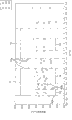
According to the present invention, as from will understanding the analysis that will describe after a while, Ts/Td has been controlled so as to scope except that the scope that comprises a 81a 71 or the scope 72 that falls into Figure 11, the end portion of each the some representative among these 81a by making ink droplet from the body portion of ink droplet from the high speed ink droplet that produces.Realized a kind of ink gun like this, in this ink gun, the end portion of each ink droplet is difficult to separate, thereby the repeatability of image is higher.
Description of drawings
Of the present invention other will more fully manifest from the description below in conjunction with accompanying drawing with other purpose, feature and advantage, in the accompanying drawings:
Fig. 1 illustrates the total structure of conduct according to the printer of the ink jet recording device of the embodiment of the invention;
Fig. 2 is the top view of head main body shown in Figure 1;
Fig. 3 is an enlarged drawing of using the chain-dotted line area surrounded among Fig. 2;
Fig. 4 is the vertical cross section along the line IV-IV among Fig. 3;
Fig. 5 is near the partial enlarged drawing of piezo-activator shown in Figure 4;
Fig. 6 is the block diagram that is illustrated in the structure of the controller that comprises in the printer shown in Figure 1;
Fig. 7 is a curve map, and the example of the potential change of the single electrode of having supplied voltage pulse signal is shown;
Fig. 8 is A, the type of drive of piezo-activator when thereby 8B and 8C are illustrated in current potential by supply voltage pulse signal single electrode and change as shown in Figure 7;
Fig. 9 A, 9B and 9C illustrate the ink droplet that sprays from nozzle when the pulse voltage corresponding to Fig. 7 is fed to single electrode;
Figure 10 A is illustrated in the equivalent circuit that uses in the present inventor's the analysis, and this equivalence circuit is to obtain by independent black path shown in Figure 4 is carried out modeling;
Figure 10 B illustrates the structure of the first's path in the fluid analysis unit shown in Figure 10 A;
Figure 10 C illustrates the structure of nozzle in the first's path shown in Figure 10 B;
Figure 11 is a curve map, illustrates by utilizing the result of the numerical analysis that the model shown in Figure 10 A to Figure 10 C carries out; And
Figure 12 is another curve map, illustrates by utilizing the result of the numerical analysis that the model shown in Figure 10 A to Figure 10 C carries out.
The specific embodiment
The preferred embodiments of the present invention and the present inventor's analysis result is described hereinafter with reference to accompanying drawing.
Fig. 1 illustrates the total structure according to the color inkjet printer of the embodiment of the invention.Printer 1 comprises four ink guns 2 therein.Ink gun 2 is fixed on the printer 1 under the state of arranging along the throughput direction of print paper P.Each ink gun 2 has the elongated profile that extends perpendicular to Fig. 1.
Between paper feed unit 114 and supply unit 120, be provided with two couples of feed roller 118a and 118b and 119a and 119b along the transport path of print paper P.Every the print paper P that sends from paper feed unit 114 is delivered to supply unit 120 by these feed roller guiding.
As shown in Figure 1, a leather belt roller 106 is connected to and carries motor 174.Carry motor 174 that leather belt roller 106 is rotated in the direction of arrow A.Another leather belt roller 107 can be followed belt conveyor 111 and be rotated.Therefore, carry motor 174 to make leather belt roller 106 rotations, belt conveyor 111 is moved along the direction of arrow A by driving.
Near leather belt roller 107, nip roll 138 and be subjected to nip roll 139 to be arranged to cramping belt conveyor 111.Nip roll 138 is by unshowned spring biased downward.The nip roll 139 that is subjected to that is arranged on nip roll 138 belows is accepted by the power of the nip roll 138 of biased downward by belt conveyor 111.Nip roll 138 and be subjected to nip roll 139 the two all can rotate freely, and follow belt conveyor 111 and rotate.
Every the print paper P that delivers to supply unit 120 from paper feed unit 114 is between nip roll 138 and belt conveyor 111.Therefore, print paper P is forced on the feed surface 127 of belt conveyor 111, thereby is attached on the feed surface 127.Open P by the rotation of belt conveyor 111 to ink gun 2 fed printing sheet then.The outer surface 113 of belt conveyor 111 can be handled with adhesive silicone rubber.In this case, print paper P can positively be attached on the feed surface 127 of belt conveyor 111.
Four ink guns 2 are arranged along the throughput direction of belt conveyor 111 close to each otherly.Each ink gun 2 has head main body 13 at its lower end.As shown in Figure 3, on the lower surface of each head main body 13, be formed with a large amount of nozzle 8, China ink each nozzle ejection from these nozzles 8.From being formed on the China ink of the nozzle 8 ejection same colors on the ink gun 2.Four ink guns 2 spray the China ink of magenta (M), yellow (Y), cyan (C) and black (K) respectively.Each ink gun 2 is arranged so that the narrow space of formation between the feed surface 127 of its head main body 13 and belt conveyor 111.
Every the print paper P that is carried by belt conveyor 111 is by the space between each ink gun 2 and the belt conveyor 111.At this moment, China ink sprays to the upper surface of print paper P from the head main body 13 of ink gun 2.Like this, on the upper surface of print paper P, form the coloured image that is stored in the view data in the memory based on instruction by controller 100.
Between supply unit 120 and paper receiving unit 116, be provided with: peel plate 140; With two couples of feed roller 121a and 121b and 122a and 122b.Every the print paper P that has printed the chromatic colour image is carried to peel plate 140 by belt conveyor 111.The right hand edge that print paper P is stripped from plate 140 is then peeled off the feed surface 127 of belt conveyor 111.Print paper P is fed roller 121a to 122b then and delivers to paper receiving unit 116.The print paper P that has printed is sent to paper receiving unit 116 so successively, is stacked on then on the paper receiving unit 116.
In nip roll 138 be arranged between the ink gun 2 at upstream-most position place of throughput direction of print paper P paper sensor 133 is set.Paper sensor 133 is made of light-emitting component and light receiving element, thereby can detect the leading edge of every print paper P on the transport path.The testing result of paper sensor 133 is sent to controller 100.Based on the testing result of sending from paper sensor 133, controller 100 can be controlled each ink gun 2, carry motor 174 etc., makes that the printing of the conveying operations of every print paper P and image is synchronized with each other.
Then, will the head main body 13 of each ink gun 2 be described.Fig. 2 is the top view of head main body 13 shown in Figure 1.
Head main body 13 comprises path unit 4 and four actuating units 21 that all are attached on this path unit 4.Each actuating unit 21 is roughly trapezoidal.Each actuating unit 21 is arranged on the upper surface of path unit 4, makes the trapezoidal pair of parallel of actuating unit 21 to the longitudinal extension of edge path unit 4.Along arranging two actuating units 21 on every straight line in two straight lines that vertically extend parallel to each other of path unit 4.That is, four actuating units 21 are the z font on the whole and are arranged on the path unit 4.Each adjacent hypotenuse transversely overlapping each other of the actuating unit 21 on the path unit 4 at path unit 4.
Be formed with collector passage 5 in path unit 4, each the collector passage in these collector passages 5 all is the part of black path.The opening 5b of each collector passage 5 is formed on the upper surface of path unit 4.Along path unit 4 vertically extend parallel to each other as every straight line in two straight lines of imaginary line on arrange five opening 5b.That is, form ten opening 5b altogether.Opening 5b forms the zone of avoiding being provided with four actuating units 21.China ink is fed to this collector passage 5 from the opening 5b of unshowned ink container by each collector passage 5.
Fig. 3 is an amplification top view of using the chain-dotted line area surrounded among Fig. 2.For convenience of explanation, in Fig. 3, each actuating unit 21 is shown with double dot dash line.In addition, hole 12, nozzle 8 etc. are shown, although they should be shown in broken lines, because they are formed in the path unit 4 or on the lower surface of path unit 4 with solid line.
Each the collector passage 5 that is formed in the path unit 4 is branched off into a plurality of secondary collector passage 5a.Collector passage 5 extends along the hypotenuse of actuating unit 21, thereby intersects with the longitudinal axis of path unit 4.In the zone between two actuating units 21, adjacent actuating unit 21 shared collector passages 5.Secondary collector passage 5a branches out from the both sides of collector passage 5.Secondary collector passage 5a is formed in the path unit 4, thereby adjacent one another are in the zone relative with each actuating unit 21.
In pressure chamber 10 and the single electrode 35 any one is vertically longer in Fig. 3.In pressure chamber 10 and the single electrode 35 any one all attenuates up and down from its vertical centre.This has realized a large amount of pressure chamber 10 and a large amount of intensive layout of single electrode 35 in respective planes.
On path unit 4, be formed with big flow nozzle 8 as spout.These nozzles 8 be arranged to avoid path unit 4 lower surface with the relative zone of secondary collector passage 5a.Nozzle 8 is arranged in the zone relative with associated actuators unit 21 of lower surface of path unit 4.Nozzle 8 in each zone all is arranged in each all along on a large amount of straight lines of the longitudinal extension of path unit 4 at interval with rule.
In path unit 4, be formed with a large amount of holes 12.These holes 12 are arranged in the zone relative with relevant pressure chamber group 9.In this embodiment, hole 12 horizontal-extending in parallel with each other.
In path unit 4, form connecting hole so that each corresponding hole 12, pressure chamber 10 and nozzle 8 are interconnected.As shown in Figure 4, these connecting holes interconnect to form independent black path 32.Each independent black path 32 all connects with corresponding secondary collector passage 5a.The China ink that is fed to each collector passage 5 is fed to each independent black path 32 by the secondary collector passage 5a of correspondence, then from nozzle 8 ejections of correspondence.
Then, will the profile construction of head main body 13 be described.Fig. 4 is the vertical cross section along the line IV-IV among Fig. 3.
The path unit 4 of head main body 13 has the hierarchy that a plurality of plate layerings are placed.That is, be sequentially with cavity plate 22, substrate 23, hole plate 24, feeding plate 25, tube plate 26,27,28, cover plate 29 and nozzle plate 30 according to what the upper surface from path unit 4 began.In every block of plate, be formed with a large amount of connecting holes.After these plates being located such that the connecting hole that passes each piece plate formation interconnects, these plate layerings are placed, to form each independent black path 32 and each secondary collector passage 5a.As shown in Figure 4, in head main body 13, the part that constitutes each independent black path 32 is arranged on different positions close to each otherly, promptly, pressure chamber 10 is formed near the upper surface of path unit 4, secondary collector passage 5a is formed on the inside at the middle part of path unit 4, and nozzle 8 is formed on the lower surface of path unit 4.Connecting hole makes secondary collector passage 5a be connected with nozzle 8 by pressure chamber 10.
The connecting hole that each piece plate forms is passed in description.First is to pass the pressure chamber 10 that cavity plate 22 forms.Second is the connecting hole A that is provided with as leading to the second portion path of secondary collector passage 5a from an end of pressure chamber 10.Pass from as the substrate 23 of the inlet of pressure chamber 10 to as the plate of the feeding plate 25 of the outlet of secondary collector passage 5a and form this connecting hole A.Connecting hole A comprises the hole 12 that passes 24 formation of hole plate.
The 3rd is the connecting hole B that is provided with as leading to first's path of nozzle 8 from the other end of pressure chamber 10.Pass from as the substrate 23 of the outlet of pressure chamber 10 to the plate of nozzle plate 29 and form this connecting hole B.Below will call descender 33 to connecting hole B.The 4th is to pass the nozzle 8 that nozzle plate 30 forms.The descender 33 of formation thereby nozzle 8 matches with connecting hole B as first's path.The 5th is the connecting hole C that is used to form secondary collector passage 5a.Pass tube plate 26 to 28 and form this connecting hole C.
Thereby above connecting hole interconnects and forms independent black path 32, and this independent black path 32 is that nozzle 8 is led in the outlet of secondary collector passage 5a from the black inlet port from secondary collector passage 5a.The China ink that is fed to secondary collector passage 5a flow to nozzle 8 in underpass.At first, China ink upwards flow to an end of hole 12 from secondary collector passage 5a.Then, China ink flow to the other end of hole 12 along the vertical equity of hole 12.China ink upwards flow to an end of pressure chamber 10 then from the described other end of hole 12.China ink flow to the other end of pressure chamber 10 then along the vertical equity of pressure chamber 10.China ink is tilted to current downflow and moving to the nozzle 8 that is positioned under the connecting hole C by three blocks of plate currents then.
The connecting hole 23a and the nozzle 8 that comprise the border 23b between descender 33 and pressure chamber 10 are narrower than the other parts of descender 33.That is be that the sectional area of connecting hole 23a and nozzle 8 is less than the sectional area of the other parts of descender 33 in the vertical cross section of the counterpart of double-headed arrow of independent black path shown in Fig. 4, at longitudinal axis with descender 33.This is following a kind of structure, wherein is easy to produce near the intrinsic vibration of two ends nozzle 8 and connecting hole 23a relatively in the China ink of filling descender 33.
The longitudinal axis with hole 12 of hole 12 be the vertical cross section of the counterpart of double-headed arrow of independent black path shown in Fig. 4 area than connecting hole A with the area of the outlet 25a of the area at the 23c place, border of pressure chamber 10 and secondary collector passage 5a in arbitrary area little.Therefore, hole 12 has been realized being suitable for by spraying the structure of preceding fill method ink-jet as limited path like this.
As shown in Figure 5, each actuating unit 21 all has the hierarchy with four piezoelectric layers 41,42,43 and 44 layerings placement.Each piezoelectric layer in the piezoelectric layer 41 to 44 has about 15 microns thickness.The whole thickness of actuating unit 21 is about 60 microns.As shown in Figure 3, any piezoelectric layer in the piezoelectric layer 41 to 44 is arranged in a large amount of pressure chamber 10.Each piezoelectric layer in the piezoelectric layer 41 to 44 is made by having ferroelectric lead zirconate titanate (PZT) base ceramic material.
Actuating unit 21 comprises single electrode 35 and public electrode 34, and each in single electrode 35 and the public electrode 34 is made by for example Ag-Pd Base Metal material.As previously mentioned, each single electrode 35 all is arranged on the upper surface of actuating unit 21, thereby relative with corresponding pressure chamber 10.One end of single electrode 35 extends to outside the zone relative with pressure chamber 10, and forms pad 36 on this extension.Pad 36 is made by the gold that for example contains glass dust.Pad 36 has about 15 microns thickness, and forms projectedly.Pad 36 is electrically connected to the contact that is arranged on the unshowned flexible print circuit (FPC).Such as will be described later, controller 100 is supplied potential pulses by FPC to each single electrode 35.
As shown in Figure 5, each single electrode 35 and public electrode 34 all are arranged to only clip uppermost piezoelectric layer 41.The zone that independent electrode 35 of the quilt of this piezoelectric layer and public electrode 34 clip is called active part.In each actuating unit 21 of this embodiment, have only uppermost piezoelectric layer 41 to comprise such active part therein, and remaining piezoelectric layer 42 to 44 does not comprise active part therein.That is, actuating unit 21 has so-called single piezoelectric chip structure.
Such as will be described later, when optionally the predetermined voltage pulse being fed on each single electrode 35, pressure is applied on the China ink in the pressure chamber 10 corresponding with this single electrode 35.Therefore, China ink is by nozzle 8 ejections of corresponding independent black path 32 from correspondence.That is, the part relative of actuating unit 21 with each pressure chamber 10 as and pressure chamber 10 and corresponding nozzle 8 corresponding independent piezo-activators 50.In the hierarchy that constitutes by four piezoelectric layers, at each pressure chamber's 10 formation this actuator as shown in Figure 5 as cellular construction.Construct each actuating unit 21 like this.In this embodiment, be about 5 to 7p1 (skin liters) by a spraying from the China ink amount that nozzle 8 sprays.
Based on said structure, each piezo-activator 50 and corresponding independent black path 32 are designed so that: because the natural period of oscillation Td of the China ink of the natural period of oscillation Ts of the vibration that a body deformability of piezo-activator 50 and corresponding pressure chamber 10 causes, the corresponding descender 33 of filling and the natural period of oscillation Tc that fills the China ink of whole independent black path 32 meet the following conditions.That is, Ts/Td is being not less than 0.36 and be not more than in 0.90 the scope, perhaps is being not less than 1.1 and be not more than in 1.7 the scope, and Ts * Td/Tc
2Be not less than 0.0060 and be not more than in 0.014 the scope.
In above condition, Ts depends on following parameter: the area of corresponding single electrode 35, thickness and material; The thickness of public electrode 34 and material; The material of each piezoelectric layer in the piezoelectric layer 41 to 44 and thickness; The area in the zone relative with relevant pressure chamber 10 and single electrode 35.In addition, Td depends on the parameter such as shape, length and the sectional area of descender 33.And Tc depends on the parameter such as the shape of independent black path 32, length and sectional area.When the independent black path 32 of design, for example be the suitable numerical value of above parameter setting; Then by utilizing fluid analysis etc. to calculate Ts, Td and Tc; Judge then whether Ts, the Td and the Tc that calculate satisfy above scope.Determine to satisfy the optimum specifications of independent black path 32, descender 33 and the piezo-activator 50 of above scope by replicate analysis.Based on the specification of determining like this, form each independent black path 32, each descender 33 and each piezo-activator 50 of this embodiment.In this embodiment, in fluid analysis, each descender 33 all is considered to straight tube as will be described later.Yet each descender 33 can be considered to be the combination of the different pipe of internal diameter according to the true form of this descender 33.
Then, will the control of actuating unit 21 be described.In order to control actuating unit 21, printer 1 comprises controller 100 and driver IC 80 therein.Printer 1 comprises therein: as the CPU (CPU) of arithmetic processing unit; Read-only storage (ROM), storage is by the computer program of CPU execution and the data of using in these programs in this read-only storage (ROM); And the random-access memory (ram) that is used for temporarily storing the executory data of computer program.These parts formations have the controller 100 of function as will be described below.
As shown in Figure 6, controller 100 comprises print control unit 101 and operation control unit 105 therein.Print control unit 101 comprises that therein image data storage part 102, waveform patterns storage area 103 and print signal produce part 104.Image data storage part 102 is stored therein from the next view data that is used to print of for example personal computer (PC) 133 transmission.
Waveform patterns storage area 103 is stored and a large amount of corresponding Wave datas of injection pulse train wave shape therein.Each injection pulse train wave shape is all corresponding to the basic waveform according to tone of image etc.Driver IC 80 via correspondence is fed to single electrode 35 with the voltage pulse signal corresponding with waveform, thereby from each ink gun 2 ejection and every kind of China ink amount that tone is corresponding.
Print signal produces part 104 and produces serial print data based on the view data that is stored in the image data storage part 102.Print data corresponding to be stored in waveform patterns storage area 103 in the corresponding data item of respective spray spike train waveform in a data item.Print data is used for indication and regularly injection pulse train wave shape is fed to each single electrode 35 with predetermined.Based on the view data that is stored in the image data storage part 102, print signal produces part 104 and produces print data according to timing, waveform and single electrode accordingly with view data.Print signal produces part 104 and then the print data that is produced is outputed to each driver IC 80.
For each actuating unit 21 all is provided with driver IC 80.Driver IC 80 comprises shift register, multiplexer and drives buffer, but they all do not illustrate.
Shift register will be converted into parallel data from the serial print data that print signal produces part 104 output.That is, shift register according to the indication of print data to the piezo-activator 50 outputs independent data item corresponding with each pressure chamber 10 and corresponding nozzle 8.
Multiplexer is based on selecting a suitable Wave data item from the Wave data item of each data item from be stored in waveform patterns storage area 103 of shift register output.Multiplexer is exported selected data item to driving buffer then.
Drive buffer and produce voltage pulse signal with predetermined level based on Wave data item from multiplexer output.Drive buffer and by FPC voltage pulse signal is supplied to the single electrode 35 corresponding with each piezo-activator 50 then.
Then will describe voltage pulse signal and receive the variation of current potential of the single electrode 35 of this signal.
Each voltage constantly that is contained in the voltage pulse signal will be described in.Fig. 7 illustrates the example of variation of the current potential of the single electrode 35 of having supplied voltage pulse signal.The waveform 61 of voltage pulse signal shown in Figure 7 is for being used for from the example of the waveform of a China ink of nozzle 8 ejections.
At moment t1, beginning is to single electrode 35 supply voltage pulse signals.According to from the timing controlled of the nozzle corresponding 8 ejection China inks t1 constantly with single electrode 35.In the waveform 61 of voltage pulse signal, remain at voltage in the period of moment t1 and in the period after moment t4 and to be not equal to zero U0.During period from moment t2 to moment t3, voltage remains on earth potential.Period from moment t1 to moment t2 is a transition period, and the current potential of single electrode 35 is changed to earth potential from U0 in this transition period.Period from moment t3 to moment t4 is a transition period, and the current potential of single electrode 35 is changed to U0 from earth potential in this transition period.As shown in Figure 5, each actuator 50 has and the capacitor identical construction.Therefore, when the potential change of single electrode 35, along with the accumulation of electric charge with emit and above transition period occurs.
Then will be described in and when the above voltage pulse signal of single electrode 35 supplies, how drive piezo-activator 50.
In each actuating unit 21 of this embodiment, has only uppermost piezoelectric layer 41 along from the direction polarization of each single electrode 35 towards public electrode 34.Therefore, thereby when single electrode 35 be set in the current potential different with public electrode 34 along the direction identical with polarised direction, more particularly along from single electrode 35 when the direction of public electrode 34 applies electric field to piezoelectric layer 41, the part that has been applied with electric field is that active part is attempted on thickness promptly perpendicular to this layer elongation.At this moment, active part is attempted to be parallel to this layer and is promptly shunk in the plane of this layer.On the other hand, remaining three piezoelectric layer 42 to 44 does not have polarized, thus even their also unautogenous distortion when they are applied electric field.
Therefore between piezoelectric layer 41 and piezoelectric layer 42 to 44, produce and distort difference.Therefore, each piezo-activator 50 is deformed into as a whole to the pressure chamber 10 of correspondence and promptly protrudes to piezoelectric layer 42 to 44 sides, and this is called as single piezoelectric chip distortion.
The driving of piezo-activator 50 when will the voltage pulse signal corresponding with waveform 61 being fed on the corresponding single electrode 35 then will be described.Fig. 8 A to Fig. 8 C illustrates piezo-activator 50 over time.
Fig. 8 A illustrates the state of piezo-activator 50 in the period of t1 extremely constantly shown in Figure 7.At this moment, the current potential of single electrode 35 is U0.Piezo-activator 50 is projected in the corresponding pressure chamber 10 by above-mentioned single piezoelectric chip distortion.This moment, the volume of pressure chamber 10 was V1.This state of pressure chamber 10 will be called as first state.
Fig. 8 B illustrates the state of piezo-activator 50 during period from moment t2 to moment t3 shown in Figure 7.At this moment, single electrode 35 is at earth potential.Therefore, the electric field that is applied on the active part of piezoelectric layer 41 disappears, and piezo-activator 50 is disengaged its single piezoelectric chip distortion.The volume V 2 of pressure chamber 10 is greater than the volume V 1 of the pressure chamber 10 shown in Fig. 8 A at this moment.This state of pressure chamber 10 will be called as second state.Because the increase of the volume of pressure chamber 10, China ink is drawn into the pressure chamber 10 from the secondary collector passage 5a of correspondence.
Fig. 8 C illustrates the state of piezo-activator 50 in the period after moment t4 shown in Figure 7.At this moment, the current potential of single electrode 35 is U0.Therefore, piezo-activator 50 has returned to first state once more.Make pressure chamber 10 change into first state like this by piezo-activator 50, pressure is applied on the China ink in the pressure chamber 10 from second state.Therefore with nozzle 8 ejections of ink droplet from correspondence.Ink droplet impacts the print surface of print paper P to form point.
As mentioned above, in the driving of the piezo-activator 50 of this embodiment, at first, produced NPW, as from shown in Fig. 8 A to Fig. 8 B thereby the volume of pressure chamber 10 once increased in the China ink in pressure chamber 10.This pressure wave is by the end reflections of the black path in the path unit 4, thereby returns as the positive pressure wave that advances to nozzle 8.By estimating that positive pressure wave arrives the timing of pressure chamber 10 inside, reduce the volume of pressure chamber 10 once more, as from shown in Fig. 8 B to Fig. 8 C.Fill method before the so-called injection that Here it is.
In order to realize ink-jet, the pulse width T o of as shown in Figure 7 the potential pulse with the waveform 61 that is used for ink-jet is adjusted to 1AL (acoustic length) by fill method before the above-mentioned injection.In this embodiment, each pressure chamber 10 all is arranged near the central authorities of whole length of corresponding independent black path 32, and AL is the pressure wave that produces in the pressure chamber 10 advances to the time period of corresponding nozzle 8 from the hole 12 of correspondence a length.In this structure, Fan She positive pressure wave is added on the positive pressure wave that the distortion of piezo-activator 50 owing to correspondence produces as mentioned above, thereby China ink is applied higher pressure.Therefore, the situation that only reduces once to release China ink with the volume of pressure chamber 10 is wherein compared, and when ejection same amount black, the driving voltage that is used for piezo-activator 50 keeps lower.Therefore, at the high integration of pressure chamber 10, the densification of ink gun 2 and the aspects such as operating cost that drive ink gun 2, fill method is favourable before spraying.
Then the analysis that the present inventor carries out will be described.
The present inventor has confirmed that traditional ink gun has following problem.Fig. 9 A illustrates the ink droplet that sprays from the nozzle of ink gun by the potential pulse that is adjusted to To=AL in the mode of example, and this ink gun has as Fig. 2 to structure shown in Figure 5.In order to ensure the repeatability of the image that will print based on view data, the ink droplet of appropriate amount must impact in corresponding appropriate position according to view data.For this purpose, any nozzle all sprays the ink droplet number of expectation ideally with the jet velocity of expectation in each ink ejection operation.In the ink gun of above embodiment, desirable condition is: spray two ink droplet L1 and L2 at a predetermined velocity in succession in each the injection, shown in Fig. 9 A.
Fig. 9 B and Fig. 9 C illustrate other situation of the ink droplet of ejection under the same conditions.In the situation of Fig. 9 B, produce another ink droplet L4, rather than two desirable ink droplets.In the situation of this external Fig. 9 C, produce three ink droplet L5, L6 and L7.Producing three ink droplets so altogether is because the part of ink droplet is separated from two original ink droplets.When producing the ink droplet different with two desirable ink droplets like this, its volume ink droplet different with the volume of expectation impacts in the position different with each point of view data.This has reduced the repeatability of the image that will form by ink gun.
Should be understood that above problem is mainly caused by the structure of each black path, and do not depend on kind of actuator etc. especially.
The present inventor thinks that isolating ink droplet from the ink droplet of expectation as mentioned above is owing to following reason.
Before utilizing so-called the injection in the ink-jet of fill method, at first, negative pressure is applied on the China ink in each pressure chamber 10.The NPW of Chan Shenging is reflected by the hole 12 of correspondence like this, thereby becomes positive pressure wave.Turn back to the timing of pressure chamber 10 at positive pressure wave, normal pressure is applied in the pressure chamber 10, as shown in Figure 4.Superpose by filling the pressure wave that produces in the China ink of independent black path 32 like this, thereby ejection is black effectively.
On the other hand, what can expect is to exert pressure by piezo-activator 50 not only to cause advancing wave in the China ink in the independent black path 32, but also may cause the local intrinsic vibration in the China ink in the zone of independent black path 32.The present inventor thinks that this part intrinsic vibration causes making as mentioned above ink droplet to separate.That is, because the peak value of the peak value of the pressure wave that produces owing to local intrinsic vibration and the above-mentioned advancing wave in the nozzle 8 is overlapping, thereby compare with the situation that does not have local intrinsic vibration, the jet velocity of China ink increases.As a result, the end portion of ink droplet from the ink droplet body portion from, thereby produce little ink droplet at a high speed.
Below be the more details of above-mentioned phenomenon.In ink-jet, when because the distortion of corresponding piezo-activator 50 and when in the China ink of stuffing pressure chamber 10, producing pressure wave, this pressure wave in pressure chamber 10 upstream and downstream advance.In the fill method, the volume of pressure chamber 10 once increased before injection, then through with pulse width T o time corresponding after make pressure chamber 10 return to its original volume once more, thereby from the nozzle ejection China ink of correspondence.At first, when the volume of pressure chamber 10 increases, produce NPW in the China ink in the pressure chamber 10, this NPW will be called as first pressure wave.Successively, when the volume of pressure chamber 10 reduces, produce positive pressure wave, this positive pressure wave will be called as second pressure wave.
As mentioned above, a part of advanced downstream of these pressure waves is in descender 33.For example, advanced to first pressure wave in the descender 33, that is, be positioned near the partial reflection of border between pressure chamber 10 and the descender 33 and nozzle 8 by the two ends of descender 33 reflections.These back waves bring out intrinsic vibration in the China ink of filling descender 33.This intrinsic vibration that produces in descender 33 is the example of above-mentioned local intrinsic vibration.
On the other hand, secondary collector passage 5a's part of first pressure wave towards correspondence advances to the upstream of pressure chamber 10.First pressure wave is reflected by hole 12 path midway, thereby becomes the pressure sign pressure wave of negate.Pressure symbol this pressure wave of negate advances to nozzle 8 by pressure chamber 10 and descender 33.That is, first pressure wave is made the negate of pressure sign by hole 12 reflex times, and the reflection pressure wave turn back to pressure chamber 10 as positive pressure wave, this positive pressure wave will be called as the 3rd pressure wave.Piezo-activator 50 produces second pressure wave in the China ink in pressure chamber 10 then., just China ink is sprayed from nozzle 8 when thereby second pressure wave wherein has been added to complex wave that the 3rd pressure wave forms advancing wave when arriving nozzle 8.
And the part of the second and the 3rd pressure wave is added to because first pressure wave and in the intrinsic vibration that produces in descender 33.That is, any pressure wave in first to the 3rd pressure wave all helps the intrinsic vibration in the descender 33.Like this, when the advancing wave that is made of the second and the 3rd pressure wave arrives nozzle 8, in nozzle 8, observe following vibration, in this vibration, (1) move ahead ripple itself contribution, (2) first pressure waves to the contribution of the intrinsic vibration in the descender 33 and (3) second and the part of the 3rd pressure wave to the contribution of the intrinsic vibration in the descender 33 mutual superposition all.
What can expect is: in nozzle 8, this vibration of above-mentioned contribution mutual superposition caused from the increase of the jet velocity of the China ink of nozzle 8 ejections, thereby the end portion of ink droplet from the body portion of ink droplet from.Therefore, if in the China ink of filling descender 33, suppress intrinsic vibration, the then stack of in nozzle 8, not vibrating, thus prevent that China ink from increasing its jet velocity.
On the other hand, the intrinsic vibration of bringing out in the China ink of descender 33 is to be caused by the pressure that piezo-activator 50 is applied on the China ink in the pressure chamber 10.Therefore, be contemplated to, when piezo-activator 50 and pressure chamber's 10 1 body deformabilities, the bringing out property of intrinsic vibrations changed along with the natural period of oscillation of vibration in the descender 33.Promptly, when from wherein in piezo-activator 50 natural period of oscillation during with pressure chamber's 10 one vibration during near the ink gun ejection China ink of the natural period of oscillation of descender 33, the pressure wave that produces owing to a body deformability of piezo-activator 50 and pressure chamber 10 is easy to bring out the intrinsic vibration in the descender 33, i.e. resonance in the descender 33.On the contrary, the natural period of oscillation when in piezo-activator 50 and the vibration of pressure chamber 10 one and the natural period of oscillation of descender 33 be when differing widely, and the pressure wave that produces owing to a body deformability of piezo-activator 50 and pressure chamber 10 is difficult to bring out the intrinsic vibration in the descender 33.
In order to confirm the above, the present inventor has carried out following numerical analysis.Figure 10 A to Figure 10 C is used to explain this numerical analysis.
In numerical analysis, by as shown in Figure 4 independent black path is promptly constructed circuit from the acoustics equivalent transformation that the black inlet port from secondary collector passage 5a leads to the path of nozzle 8.This equivalence circuit is carried out acoustic analysis.Figure 10 A illustrates this equivalence circuit.
As will be described below equivalent circuit corresponding to as shown in Figure 4 and Figure 5 black path and actuator of example.Therefore, in the following description, terms such as shown in Figure 4 and Figure 5 descender 33, piezo-activator 50 will for example be used.Yet the information of the necessary for example relevant actuator shown in Figure 5 of numerical analysis is acoustic compliance.Therefore, in having any actuator that is used for the China ink of pressure chamber is exerted pressure of identical acoustic compliance, obtain identical numerical analysis result.That is, as for example not only can being applied to path unit 4 and piezo-activator 50 as shown in Figure 4 and Figure 5 by the following result that the numerical analysis of describing is obtained, but also can be applied to satisfy any ink gun of used condition in this numerical analysis.
In the acoustic analysis in numerical analysis, utilized: the thickness of piezo-activator 50; The area of pressure chamber 10 and perpendicular to the degree of depth of piezoelectric layer; The width of hole 12, length and perpendicular to the degree of depth of piezoelectric layer; Or the like.Obtain the acoustic compliance of piezo-activator 50 and the pressure constant that will produce by piezo-activator 50 from above data in advance such as piezo-activator 50 by finite element technique, this acoustic compliance be with equivalent circuit in the corresponding acoustic capacitance of electric capacity of capacitor 250.Piezoelectric constant obtains by the resonance method of utilizing the impedance of measuring piezoelectric element.
As mentioned above, fluid analysis unit 233 is corresponding to descender 33.Figure 10 B illustrates the overall structure of descender 33 as shown in Figure 4, and it is rendered as the form that is adopted in the fluid analysis of fluid analysis unit 233.Figure 10 C illustrates the structure of the part of the nozzle plate 30 in the descender 33.The left end of Figure 10 B is connected with pressure chamber 10.
In fluid analysis, prepared six ink guns, these ink guns are different aspect the thickness of the internal diameter of descender 33 and length and the oscillating plate that comprises in piezo-activator 50.In each ink gun in ink gun a to f, at inside diameter D 1 and D2 and length L 1, L2 and the L3 of the each several part of descender 33 shown in following table 1 that will provide and the table 2.Inside diameter D 1 is corresponding to the internal diameter of the part that forms in the plate except nozzle plate 30 of descender 33.Inside diameter D 2 is corresponding to the internal diameter of nozzle 8.In numerical analysis, shown in Figure 10 B, this part that forms in the plate except nozzle plate 30 of descender 33 all has identical internal diameter in any position.Shown in Figure 10 C, the part that forms in nozzle plate 30 has the structure that attenuates to nozzle 8.All has identical inside diameter D 2 near the part in the scope of length L 3 nozzle 8 in any position.Near the inner surface of the part the inner surface of taper portion and the nozzle 8 forms the angle of 8 degree in the profile of Figure 10 C, as shown in table 2.
In each ink gun in ink gun a to f, at the thickness of oscillating plate shown in the table 1.Oscillating plate is corresponding to piezoelectric layer shown in Figure 5 42 to 44.Natural period of oscillation Ts from the one vibration of the THICKNESS CALCULATION piezo-activator 50 of oscillating plate and pressure chamber 10.The natural period of oscillation Ts of each ink gun among the ink gun a to f is shown with microsecond in table 1.In each ink gun, having analyzed wherein, length L 1 is set at 200 microns, 400 microns, 600 microns, 800 microns and 1000 microns (1 micron=10
-6M) situation.Table 3 illustrates the natural period of oscillation Td according to each length L 1 value of the China ink of filling descender 33 with microsecond.
Suppose each ink gun ink-jet under the effect of the driving voltage shown in the table 1 among the ink gun a to f.Driving voltage is corresponding to the height of the potential pulse on the single electrode 35 that is fed to piezo-activator 50.That is, driving voltage is illustrated in the maximum potential difference U0 between single electrode 35 and the public electrode 34, as shown in Figure 7.
Table 1
Table 2
| D1 | D2 | L2 | L3 | θ | |
| 220μm | | 50μm | 10μm | 8 degree |
Table 3
| L1 | 200μm | 400μm | 600μm | 800μm | 1000μm |
| Td[μsec] | 0.520 | 1.04 | 1.44 | 1.89 | 2.20 |
Following table 4 illustrates the Ts/Td according to each ink gun and each L1 value.Following table 5 illustrates natural period of oscillation Tc according to the China ink of the whole independent black path 32 of filling of each ink gun and each L1 value with microsecond.
Table 4
| L1=200μm | 400μm | 600μm | 800μm | 1000μm | |
| Ink gun a | 1.49 | 0.74 | 0.54 | 0.41 | 0.35 |
| Ink gun b | 1.81 | 0.90 | 0.65 | 0.50 | 0.43 |
| Ink gun c | 2.11 | 1.05 | 0.76 | 0.58 | 0.50 |
| Ink gun d | 2.52 | 1.26 | 0.91 | 0.69 | 0.60 |
| Ink gun e | 3.00 | 1.50 | 1.09 | 0.83 | 0.71 |
| Ink gun f | 3.67 | 1.84 | 1.33 | 1.01 | 0.87 |
Table 5
| L1=200μm | 400μm | 600μm | 800μm | 1000μm | |
| Ink gun a | 12.6 | 12.8 | 13.0 | 13.2 | 13.5 |
| Ink gun b | 12.9 | 13.1 | 13.3 | 13.5 | 13.7 |
| Ink gun c | 13.3 | 13.5 | 13.7 | 13.9 | 14.1 |
| Ink gun d | 13.9 | 14.1 | 14.3 | 14.5 | 14.7 |
| Ink gun e | 14.6 | 14.8 | 15.0 | 15.2 | 15.4 |
| Ink gun f | 15.5 | 15.7 | 15.9 | 16.1 | 16.3 |
In fluid analysis unit 233 carry out fluid analysis like the plan of the fluid analysis method of compressibility formulism like compression method by plan by conduct.Intend like compression method be used for by make the Navier-Stokes equation and added the plan of represent density like the time change the continuity equation simultaneous and the method for acquisition speed and pressure.
Obtain the acoustic compliance of pressure chamber 10 by relational expression C=W/Ev, this acoustic compliance be with equivalent circuit in the corresponding acoustic capacitance C of electric capacity of capacitor 210, wherein, W represents the volume of pressure chamber 10, and Ev represents the volume elasticity of China ink.
Obtain hole 12 by relational expression m=rho * 1/A with equivalent circuit in the corresponding acoustic mass of inductance of coil 212a, wherein, rho represents black density; A represents, the i.e. area in cross section on the horizontal direction of Fig. 4 vertical with longitudinal axis hole hole 12; And the length on the horizontal direction of Fig. 4 of 1 expression hole 12.
The corresponding passage resistance of resistance R with resistor 212b of following acquisition hole 12.In the above-described embodiments, each hole 12 all vertical with the longitudinal axis of hole, be to have rectangular shape in the profile on the horizontal direction of Fig. 4, it is the limit of 2b that this rectangular shape has limit and the length that length is 2a.In this case, obtain the amount of China ink mobile in hole 12 by following formula 1.Pressure Δ p (it is corresponding to the pressure intensity of wave) in will being applied to hole 12, and hole 12 in relation between the amount Q of the China ink that flows represent by Q=Δ p/R.From relational expression 1 calculated resistance R.In formula 1, the length of 1 expression hole 12, as mentioned above.
In the fluid analysis in fluid analysis unit 233, obtain volume velocity by the China ink of fluid analysis unit 233.As and will be applied to single electrode 35 in the piezo-activator 50 and the corresponding condition of voltage between the public electrode 34, suppose that the pressure P corresponding with voltage is to be applied by the pressure source in the circuit 299.Under these conditions, based on pressure P, acoustic capacitance, acoustic mass, and resistance and the analysis result that in the fluid analysis unit, obtains, flow through the volume velocity of the China ink of circuit by the numerical analysis acquisition by independent numerical analysis.Following table 6 illustrates the result to the numerical analysis of the volume velocity of China ink.
Table 6

Table 6 illustrates jet velocity with the corresponding China ink from ink gun ejection of each Ts/Td value shown in the table 4 with m/sec.As shown in table 6, these Ts/Td values cause two kinds of different situations, that is, and and the situation that wherein sprays the situation of two ink droplets and wherein spray three ink droplets.
Figure 11 is the result's of expression table 6 curve map.In Figure 11, axis of abscissas is represented Ts/Td, and axis of ordinates is represented the jet velocity of ink droplet, is unit with m/sec.The point of drawing in the curve map of Figure 11 81,82 and 83 corresponds respectively to first, second and the 3rd ink droplet.
Shown in the some 81a of Figure 11, in the scope of Ts/Td from 0.90 to 1.1, produce three ink droplets altogether, and the jet velocity of first ink droplet in the jet velocity of first ink droplet and any other scope is compared quite high.That is, each some 81a represents shown in Fig. 9 B by separate the high speed ink droplet that produces with original ink droplet.
Above-mentioned the analysis showed that:, just solved the problems referred to above when ink gun is configured such that Ts and Td satisfy Ts/Td and be not less than 0.36 and be not more than 0.90 or be not less than 1.1 and when being not more than 1.7 condition.In this condition, the natural period of oscillation of the vibration that Ts representative causes owing to a body deformability of actuator and pressure chamber.Natural period of oscillation of China ink of first's path of the jet in the independent black path of exporting to of pressure chamber is filled in Td representative.
Owing to the vibration that a body deformability of actuator and pressure chamber causes is as follows.When drive actuator, actuator and corresponding pressure chamber's one body deformability.At this moment, when actuator progressively changes between first state and second state, actuator and pressure chamber's one vibration, and this one vibration decay gradually owing to the elasticity of actuator and pressure chamber.
The poised state of vibration has been finished and the undeformed state of actuator and pressure chamber corresponding to the decay of wherein vibration, i.e. the undeformed state of actuator wherein.For example, under the situation of as shown in Figure 5 piezo-activator 50, the poised state of vibration is zero state corresponding to the potential difference between single electrode 35 and the public electrode 34 wherein, that is, and and the state shown in Fig. 8 B.This is because when the potential difference between the electrode is zero, do not produce piezoelectricity in the piezo-activator 50 and distort, thereby piezo-activator 50 is indeformable.
When actuator changed between first state and second state, pressure was applied on the China ink in the pressure chamber.In ink ejection operation, produce the above-mentioned one vibration of actuator and pressure chamber.Therefore, vibrating the intrinsic vibration that causes by the one of actuator and pressure chamber influences strongly to the black applied pressure in the pressure chamber.In addition, the pressure wave that produces in the China ink in the pressure chamber brings out the intrinsic vibration of the China ink in first's path.Therefore, vibrate the intrinsic vibration that the intrinsic vibration that causes also influences the China ink in first's path strongly by the one of actuator and pressure chamber.That is, if the natural period of oscillation Ts of the one of actuator and pressure chamber vibration is near the natural period of oscillation Td of the China ink in first's path, the intrinsic vibration that then is easy to produce the China ink in first's path.This is easy to cause that the ink droplet from the nozzle ejection separates.
Based on above-mentioned analysis, in each ink gun 2 of the foregoing description, the value of Ts/Td has been controlled to fall into and has all represented owing to the end portion of original ink droplet the scope 71 or the scope 72 of body portion from the scope of the some 81a of the high speed ink droplet that produces from original ink droplet except that comprising each, Ts/Td is not less than 0.36 and be not more than 0.90 in this scope 71, and Ts/Td is not less than 1.1 and be not more than 1.7 in this scope 72.This has improved the repeatability of the image that will be formed by each ink gun 2.
When Ts/Td less than scope 71 following in limited time, three rank in the intrinsic vibration of the China ink in first's path and more higher order mode become problem.Yet, wherein three rank in the intrinsic vibration of the China ink in first's path and more the higher order mode situation that becomes problem be extremely low situation of the acoustic compliance of wherein actuator or the extremely long situation of descender wherein.Like this, when Ts/Td was lower than scope 71, pressure efficiency descended.This is undesirable in design.In addition, shown in the some 83c among Figure 11, the Ts/Td that is lower than scope 71 may cause producing the 3rd ink droplet, this can think owing to three rank of the intrinsic vibration of the China ink in first's path and more higher order mode produce.For this reason, get rid of the scope that is lower than scope 71 from the above-mentioned scope of this embodiment.
On the other hand, when the natural period of oscillation of the one of actuator and pressure chamber vibration surpasses 1.7 times of the natural period of oscillation of first's path, can not guarantee enough volumes of first's path, and the vibration in first's path is easy to influence meniscus.On the contrary, when the natural period of oscillation of the one of actuator and pressure chamber vibration was lower than 1.7 times of the natural period of oscillation of first's path, the decay of the vibration in first's path just prevented to vibrate the direct meniscus that influences.For this reason, in the above-described embodiments, the natural period of oscillation of the one of actuator 50 and pressure chamber 10 vibration is set in 1.7 times of low scopes than the natural period of oscillation of descender 33.
Each ink gun is configured such that preferably that all Ts/Td satisfies Ts/Td and is not less than 0.36 and be not more than 0.90 or be not less than 1.26 and be not more than the condition of 1.5 (scopes 75 shown in Figure 11).In this structure, as shown in figure 11, Ts/Td falls in the scope of more positively only spraying two ink droplets.
In another situation, each ink gun is preferably configured as and makes Ts/Td satisfy Ts/Td to be not less than 0.36 and be not more than 0.48, be not less than 0.60 and be not more than 0.90 or be not less than 1.1 and be not more than 1.7 condition.Point 83b shown in Figure 11 is illustrated in the scope between scope 73 and the scope 74 owing to separating the ink droplet that produces from original ink droplet, and Ts/Td is not less than 0.36 and be not more than 0.48 in this scope 73, and Ts/Td is not less than 0.60 and be not more than 0.90 in this scope 74.That is, in the scope between scope 73 and 74, spray three ink droplets altogether, shown in Fig. 9 C.Ts/Td is controlled to satisfies above condition and prevented to spray three such ink droplets.This has improved the repeatability of the image that will be formed by each ink gun.
Even thereby during being configured such that the good ink gun of the repeatability of not separating image from each ink droplet of ink gun ejection, some design of first's path also may cause the reduction of the required energy efficiency of ink-jet.For example, the natural period of oscillation Td of the China ink in first's path is more little with respect to the natural period of oscillation Tc of the China ink in the whole independent black path, and then the energy loss that causes owing to the pressure-wave emission in first's path is more little.On the other hand, the natural period of oscillation Ts of the one of actuator and pressure chamber vibration is more little with respect to Tc, and then the rigidity of actuator is effective aspect energy efficiency.
According to above consideration, the viewpoint how the present inventor changes along with (Td/Tc) * (Ts/Tc) from jet speed has rearranged the result of table 6.Following table 8 illustrates the result who rearranges table 6 from this viewpoint.Following table 7 illustrates the Td * Ts/Tc at each L1 value of each ink gun
2Numerical value in the table 7 obtains from table 1,3 and 5.
Table 8 illustrate at each corresponding Td * Ts/Tc of Ts/Td in the table 6
2The jet velocity of first and second ink droplets of value.The jet velocity that table 8 also is illustrated between first and second ink droplets is poor.In table 8, the wherein ejection data of the situation of three ink droplets have altogether been got rid of.
Table 7
| L1=200μm | 400μm | 600μm | 800μm | 1000μm | |
| Ink gun a | 0.0025 | 0.0049 | 0.0066 | 0.0084 | 0.0093 |
| Ink gun b | 0.0029 | 0.0057 | 0.0077 | 0.0097 | 0.0110 |
| Ink gun c | 0.0032 | 0.0063 | 0.0084 | 0.0108 | 0.0122 |
| Ink gun d | 0.0035 | 0.0069 | 0.0092 | 0.0118 | 0.0133 |
| Ink gun e | 0.0038 | 0.0074 | 0.0100 | 0.0128 | 0.0145 |
| Ink gun f | 0.0042 | 0.0083 | 0.0112 | 0.0143 | 0.0162 |
Table 8

Figure 12 is the curve map that the result of table 8 is shown.In Figure 12, axis of abscissas is represented Td * Ts/Tc
2, and axis of ordinates represents that first and second jet velocity or jet velocity are poor.The point of drawing among Figure 12 84,85 and 86 represents that respectively first jet velocity, second jet velocity and the jet velocity between first and second are poor.
In Figure 12, line segment 84a represents the mean value of the jet velocity of point 84 representatives that scope 77 contains.With shown in the point 84, first jet velocity is constant in scope 77 as line segment 84a.On the other hand, at Td * Ts/Tc
2In the scope more than=0.014 (upper limit of scope 77), first jet velocity sharply descends, shown in line segment 84b.Therefore, at Td * Ts/Tc
2In>0.014 the scope, for the energy of being supplied, ink-jet catabiotic efficient be relatively poor.
On the other hand, at Td * Ts/Tc
2In the scope below=0.006 (lower limit of scope 77), the jet velocity difference between first and second is compared quite big with other scope.That is, compare with second jet velocity, first jet velocity is too high.This causes ink droplet to impact the skew of the timing of print paper.This has reduced the quality that will be formed on the image on the print paper.
According to above analysis, each ink gun is configured such that preferably that also Ts, Td and Tc satisfy Td * Ts/Tc
2Be not less than 0.0060 and be not more than 0.014 condition.In this condition, Tc represents to fill the natural period of oscillation of the China ink of whole independent black path 32.According to above analysis, this structure has improved the efficient of ink-jet institute energy requirement; And prevent that ink droplet from impacting the skew of the timing of print paper, thereby improved the quality that will be formed on the image on the print paper.
In the above-described embodiments, first's path narrower than the longitudinal middle part of first path with the part of the boundary vicinity of pressure chamber.This structure is easy to make and produces local intrinsic vibration in first's path.Therefore, compare, when the present invention is applied to this structure, obtain significant effect with the situation of the ink gun that wherein applies the present invention to have the structure that was difficult to cause to produce this intrinsic vibration originally.
In the above-described embodiments, the longitudinal middle part of second portion path than second portion path narrow with the boundary vicinity and near the part secondary collector passage 5a of pressure chamber 10.This structure is easy to cause producing intrinsic vibration, and wherein a position in these positions of second portion path is an end that is used to reflect.Therefore, the foregoing description has the structure that is suitable for by fill method ink-jet before spraying.
In the above-described embodiments, any one in pressure chamber 10 and the single electrode 35 has shape long along an axis and that all attenuate on from the center of this axis along the both direction of this axis in plane.This makes it possible to a large amount of pressure chamber of intensive layout and a large amount of single electrode in respective planes.This has realized the ink gun that resolution ratio is high.
Although described the present invention, obviously to those skilled in the art with apparent many alternatives, modification and variant in conjunction with the specific embodiment of above general introduction.Therefore, be intended that as the preferred embodiment of the present invention of above elaboration illustrative, rather than determinate.Can make various variations not departing under the situation of the spirit and scope of the present invention as defined by the appended claims.
Claims (11)
1. ink gun, this ink gun comprises:
Path unit, this path unit comprise common ink chamber and independent black path, and this independent black path leads to inkjet mouth from the outlet of common ink chamber by pressure chamber; And
Actuator, this actuator can optionally be taked first state and second state, in this first state, the volume of this pressure chamber is V1, and in this second state, the volume of pressure chamber is the V2 bigger than V1, actuator is second state from first state variation, turn back to first state then, thereby China ink is sprayed from this inkjet mouth
As the natural period of oscillation Ts of the vibration that produces by a body deformability of actuator and pressure chamber from inkjet mouth when China ink ejection and fill outlet the independent black path and lead to the natural period of oscillation Td of China ink of first's path of inkjet mouth and satisfy Ts/Td and be not less than 0.36 and be not more than 0.90 or be not less than 1.1 and be not more than 1.7 condition from pressure chamber.
2. ink gun according to claim 1, wherein Ts and Td satisfy Ts/Td and are not less than 0.36 and be not more than 0.48 condition.
3. ink gun according to claim 1, wherein Ts and Td satisfy Ts/Td and are not less than 0.60 and be not more than 0.90 condition.
4. ink gun according to claim 1, wherein Ts and Td satisfy Ts/Td and are not less than 1.1 and be not more than 1.7 condition.
5. ink gun according to claim 1, wherein Ts, Td and the natural period of oscillation Tc that fills the China ink of whole described independent black path satisfy Ts * Td/Tc
2Be not less than 0.0060 and be not more than 0.014 condition.
6. ink gun according to claim 1 wherein leads to the area in the zone of described first path vertical with longitudinal axis described first path cross section of described first path of described inkjet mouth greater than any area in the area of the area on the border between described first path and described pressure chamber and described jet from the outlet of described pressure chamber.
7. ink gun according to claim 1, wherein, the area that leads to the vertical cross section of the longitudinal axis with the second portion path the zone of this second portion path of second portion path of described pressure chamber of the outlet from described common ink chamber in the described independent black path is less than any area in the area of the outlet of the area on the border between second portion path and described pressure chamber and described common ink chamber.
8. ink gun according to claim 1, wherein said actuator comprises: the single electrode relative with described pressure chamber; Piezoelectric layer, this piezoelectric layer have the zone relative with described pressure chamber; And public electrode, this public electrode matches with described single electrode to clip this zone of piezoelectric layer.
9. ink gun according to claim 8, wherein have when being not equal to zero first value when the voltage between described single electrode and the described public electrode, described actuator is taked described first state, and when the voltage between described single electrode and the described public electrode had than little second value of described first value, described actuator was taked described second state.
10. ink gun according to claim 8, wherein said single electrode and described public electrode clip only piezoelectric layer.
11. ink gun according to claim 8, any one in wherein said pressure chamber and the described single electrode have shape long along an axis and that all attenuate on from the center of this axis along the both direction of this axis in plane.
Applications Claiming Priority (2)
| Application Number | Priority Date | Filing Date | Title |
|---|---|---|---|
| JP2006065215 | 2006-03-10 | ||
| JP2006065215A JP4680805B2 (en) | 2006-03-10 | 2006-03-10 | Inkjet head |
Publications (2)
| Publication Number | Publication Date |
|---|---|
| CN101037042A CN101037042A (en) | 2007-09-19 |
| CN100551702C true CN100551702C (en) | 2009-10-21 |
Family
ID=38158712
Family Applications (1)
| Application Number | Title | Priority Date | Filing Date |
|---|---|---|---|
| CNB2007100855599A Active CN100551702C (en) | 2006-03-10 | 2007-03-12 | Ink gun |
Country Status (5)
| Country | Link |
|---|---|
| US (1) | US7600861B2 (en) |
| EP (1) | EP1832425B1 (en) |
| JP (1) | JP4680805B2 (en) |
| CN (1) | CN100551702C (en) |
| DE (1) | DE602007007529D1 (en) |
Cited By (1)
| Publication number | Priority date | Publication date | Assignee | Title |
|---|---|---|---|---|
| CN106183419A (en) * | 2013-08-09 | 2016-12-07 | 精工爱普生株式会社 | Jet head liquid and liquid injection apparatus |
Families Citing this family (1)
| Publication number | Priority date | Publication date | Assignee | Title |
|---|---|---|---|---|
| JP2009083291A (en) * | 2007-09-28 | 2009-04-23 | Brother Ind Ltd | Inkjet recorder |
Family Cites Families (13)
| Publication number | Priority date | Publication date | Assignee | Title |
|---|---|---|---|---|
| US5155498A (en) | 1990-07-16 | 1992-10-13 | Tektronix, Inc. | Method of operating an ink jet to reduce print quality degradation resulting from rectified diffusion |
| JP2936358B2 (en) * | 1990-07-16 | 1999-08-23 | テクトロニクス・インコーポレイテッド | Driving method of inkjet print head |
| JP3216664B2 (en) * | 1992-12-08 | 2001-10-09 | セイコーエプソン株式会社 | Ink jet recording device |
| JP3099653B2 (en) * | 1993-10-19 | 2000-10-16 | 富士ゼロックス株式会社 | Fluid ejection device and method |
| JP3173561B2 (en) | 1995-10-31 | 2001-06-04 | セイコーエプソン株式会社 | Laminated ink jet recording head and driving method thereof |
| US5831162A (en) * | 1997-01-21 | 1998-11-03 | Delco Electronics Corporation | Silicon micromachined motion sensor and method of making |
| US6141113A (en) * | 1997-01-22 | 2000-10-31 | Brother Kogyo Kabushiki Kaisha | Ink droplet ejection drive method and apparatus using ink-nonemission pulse after ink-emission pulse |
| JP4075262B2 (en) * | 2000-01-06 | 2008-04-16 | セイコーエプソン株式会社 | Inkjet head |
| JP3687481B2 (en) * | 2000-04-13 | 2005-08-24 | セイコーエプソン株式会社 | Inkjet recording head |
| US6808254B2 (en) | 2000-11-30 | 2004-10-26 | Brother Kogyo Kabushiki Kaisha | Ink jet printer head |
| JP2003305852A (en) | 2002-02-18 | 2003-10-28 | Brother Ind Ltd | Inkjet head and inkjet printer having the same |
| JP2004114362A (en) * | 2002-09-24 | 2004-04-15 | Brother Ind Ltd | Inkjet head |
| DE602007006117D1 (en) * | 2006-09-14 | 2010-06-10 | Brother Ind Ltd | Liquid ejection head and driving method therefor |
-
2006
- 2006-03-10 JP JP2006065215A patent/JP4680805B2/en active Active
-
2007
- 2007-03-08 US US11/683,996 patent/US7600861B2/en active Active
- 2007-03-09 EP EP07250990A patent/EP1832425B1/en active Active
- 2007-03-09 DE DE602007007529T patent/DE602007007529D1/en active Active
- 2007-03-12 CN CNB2007100855599A patent/CN100551702C/en active Active
Cited By (2)
| Publication number | Priority date | Publication date | Assignee | Title |
|---|---|---|---|---|
| CN106183419A (en) * | 2013-08-09 | 2016-12-07 | 精工爱普生株式会社 | Jet head liquid and liquid injection apparatus |
| CN106183419B (en) * | 2013-08-09 | 2018-05-22 | 精工爱普生株式会社 | Liquid ejecting head and liquid injection apparatus |
Also Published As
| Publication number | Publication date |
|---|---|
| EP1832425A3 (en) | 2008-09-10 |
| DE602007007529D1 (en) | 2010-08-19 |
| JP2007237635A (en) | 2007-09-20 |
| EP1832425A2 (en) | 2007-09-12 |
| JP4680805B2 (en) | 2011-05-11 |
| US20070211090A1 (en) | 2007-09-13 |
| US7600861B2 (en) | 2009-10-13 |
| CN101037042A (en) | 2007-09-19 |
| EP1832425B1 (en) | 2010-07-07 |
Similar Documents
| Publication | Publication Date | Title |
|---|---|---|
| CN100548690C (en) | Jet head liquid and driving method thereof | |
| JP4716000B2 (en) | INK JET HEAD INSPECTION METHOD, INSPECTION SYSTEM, AND INK JET PRINTER | |
| US7628462B2 (en) | Droplet discharge device and method of driving the same | |
| EP4011628B1 (en) | Liquid ejection device and image forming apparatus | |
| EP1403047B1 (en) | Inkjet printing apparatus and actuator controller and actuator controlling method used in inkjet printing apparatus | |
| CN100558555C (en) | Ink gun | |
| CN100551702C (en) | Ink gun | |
| EP1839865B1 (en) | Inkjet recording apparatus and method of determining control condition in the apparatus | |
| CN100475537C (en) | Inkjet recording apparatus and control method for the same | |
| US20060187276A1 (en) | Ink droplet ejection device | |
| CN100519188C (en) | Inkjet printer | |
| US7520580B2 (en) | Device and method for ejecting ink droplet | |
| JP2007125881A (en) | Inkjet recording device and method of controlling the same |
Legal Events
| Date | Code | Title | Description |
|---|---|---|---|
| C06 | Publication | ||
| PB01 | Publication | ||
| C10 | Entry into substantive examination | ||
| SE01 | Entry into force of request for substantive examination | ||
| C14 | Grant of patent or utility model | ||
| GR01 | Patent grant |