CN100545373C - A lightweight component for concrete filling - Google Patents
A lightweight component for concrete filling Download PDFInfo
- Publication number
- CN100545373C CN100545373C CNB2006101372581A CN200610137258A CN100545373C CN 100545373 C CN100545373 C CN 100545373C CN B2006101372581 A CNB2006101372581 A CN B2006101372581A CN 200610137258 A CN200610137258 A CN 200610137258A CN 100545373 C CN100545373 C CN 100545373C
- Authority
- CN
- China
- Prior art keywords
- lightweight
- component
- lightweight component
- concrete filling
- groove
- Prior art date
- Legal status (The legal status is an assumption and is not a legal conclusion. Google has not performed a legal analysis and makes no representation as to the accuracy of the status listed.)
- Expired - Fee Related
Links
Images


Landscapes
- Bridges Or Land Bridges (AREA)
Abstract
一种砼填充用轻质构件,包括轻质构件(1),其特征在于在轻质构件(1)中有至少一个贯穿上下竖向的浇注孔洞(2),在轻质构件(1)外表面上有至少一条与浇注孔洞(2)的至少一端相交连通的凹槽(3),在轻质构件(1)上有至少一条与浇注孔洞(2)平行的凹槽(3),加强筋(10)设置在轻质构件内部的上壁和下壁上,所述的轻质构件(1)的至少一个面上叠合有叠合层(8)。适用于现浇钢筋砼或预应力钢筋砼的空心楼盖、屋盖、墙体、基础底板以及空腹桥梁使用。
A lightweight component for concrete filling, comprising a lightweight component (1), characterized in that the lightweight component (1) has at least one pouring hole (2) running vertically up and down, and the lightweight component (1) There is at least one groove (3) intersecting and communicating with at least one end of the pouring hole (2) on the surface, and there is at least one groove (3) parallel to the pouring hole (2) on the lightweight component (1), and the reinforcing rib (10) It is arranged on the upper wall and the lower wall inside the lightweight component, and the superimposed layer (8) is superimposed on at least one surface of the lightweight component (1). It is suitable for hollow floors, roofs, walls, foundation slabs and hollow bridges of cast-in-place reinforced concrete or prestressed reinforced concrete.
Description
本申请为申请日为2003年11月2日、申请号为200310103956.6、名称为“一种砼填充用轻质构件”的发明专利申请的分案申请。This application is a divisional application of an invention patent application with a filing date of November 2, 2003, an application number of 200310103956.6, and a title of “A Lightweight Component for Concrete Filling”.
(一)技术领域 (1) Technical field
本发明涉及一种砼填充用轻质构件。The invention relates to a lightweight component for concrete filling.
(二)背景技术 (2) Background technology
无梁楼盖是目前现浇砼楼盖应用较广的楼盖结构形式,具有施工速度快、结构高度小、室内区域可灵活分割且无需吊顶装饰等优点,其内填充的轻质构件有各种空心管和盒子,盒子有空心的或实心的。如申请人于1999年3月10日申请的专利号为ZL99232921.3、名称为“现浇钢筋砼填充用薄壁筒”实用新型专利,它由硬质薄壁管和二个堵头组成,应用于无梁楼盖中作为轻质构件使用。又如河北省石家庄市的梁军,于2000年2月23日申请的专利号为ZL00203695.9、名称为“组合砼暗肋楼盖板”实用新型专利中使用的模壳,在说明书第2页第5行至第7行描述了“模壳可以是实心的,也可以是空心的,可用植物秸杆、玻璃钢、薄铁板、玻纤水泥等轻质材料制成,其外形可根据设计要求制成长方形、圆形、多边形等形状,”,同样应用于组合砼暗肋楼盖中也是作为轻质构件使用。但无论是空心管还是盒子,作为永久轻质构件应用于楼盖后,其构件中无楼盖的受力传力构件,特别是当轻质构件尺寸较大时,表现更为明显,同时,相应的现浇楼盖板的强度与刚度相对较差。为此,申请人于2002年12月15日申请了公开号为CN1415815A、名称为“一种砼填充用轻质构件”的发明专利,它包括轻质构件,其特征在于轻质构件中有至少一个贯穿的浇注孔洞,同时,在构件外表面上有至少一条与浇注孔洞连通的凹槽。这样,由于在轻质构件上有现浇砼浇注用的孔洞贯穿轻质构件,在轻质构件应用于楼盖结构后,现浇砼进入孔洞内,待凝结硬化后,形成了现浇砼柱或墩,从而在轻质构件中形成了楼盖的受力与传力构件,大大改善了楼盖的力学性能,特别是大大改善了楼盖的抗剪、抗扭力学性能;同时,由于在构件外表面上有至少一条与浇注孔洞连通的凹槽,现浇砼进入到凹槽内形成了现浇楼盖板的加强筋或加劲肋,因而楼盖的强度与刚度大为改善,同时轻质构件还具有结构简单、强度高、制作容易、成本低等特点。这类轻质构件应用于楼盖后,均可形成单向现浇砼肋空心楼盖或者双向现浇砼密肋空心楼盖,但无法形成剪力键式双向空心楼盖,虽然贵州工业大学申请了专利号为ZL97200102.6、名称为“钢筋砼剪力键式双向空心大板”实用新型专利,它公开了一种剪力键式双向空心楼盖,具有自重轻、受力性能、抗震性能好、建筑空间可灵活划分等特点,但其施工制作非常困难,费时费力。因此,研制一种新型的砼填充用轻质构件已为急需。Beamless floor is currently the most widely used floor structure for cast-in-place concrete floors. It has the advantages of fast construction speed, small structural height, flexible division of indoor areas, and no need for ceiling decoration. A hollow tube and box, the box is hollow or solid. For example, the patent No. ZL99232921.3, which the applicant applied for on March 10, 1999, is a utility model patent named "thin-walled tube for filling cast-in-place reinforced concrete", which consists of a hard thin-walled tube and two plugs. It is used as a lightweight component in beamless floors. Another example is Liang Jun of Shijiazhuang City, Hebei Province. The patent No. ZL00203695.9 applied for on February 23, 2000, the formwork used in the utility model patent named "combined concrete concealed rib floor cover", is described in No. 2 of the specification.
(三)发明内容 (3) Contents of the invention
本发明的目的在于提供一种砼填充用轻质构件,应用于现浇砼空心楼盖后,能形成剪力键式双向空心楼盖,且具有施工方便、施工速度快等特点。The object of the present invention is to provide a lightweight component for concrete filling, which can form a shear key type two-way hollow floor after being applied to a cast-in-place concrete hollow floor, and has the characteristics of convenient construction and fast construction speed.
本发明的解决方案是在现有技术的基础上,包括轻质构件,其特征在于在轻质构件中有至少一个贯穿上下竖向的浇注孔洞,在轻质构件外表面上有至少一条与浇注孔洞的至少一端相交连通的凹槽,在轻质构件上有至少一条与浇注孔洞平行的凹槽,加强筋设置在轻质构件内部的上壁和下壁上,所述的轻质构件的至少一个面上叠合有叠合层。这样,在轻质构件应用于现浇砼空心楼盖时,将轻质构件靠紧排列,裹含在现浇钢筋砼中,在轻质构件上与浇注孔洞平行的凹槽中,现浇砼则形成了楼盖的剪力墩;施工非常方便、快捷,且强度高、刚度大,从而达到了本发明的目的。若应用于密肋楼盖时,则在轻质构件上与浇注孔洞平行的凹槽中,现浇砼则形成了现浇砼肋的加强筋,因而有效地加强了楼盖的强度与刚度,消除了应力集中现象,防止了裂缝的产生,并可承受较大的集中荷载作用而不破坏;此外,轻质构件还具有结构简单、强度高、制作容易、成本低等特点,适用于现浇钢筋砼或预应力钢筋砼的空心楼盖、屋盖、墙体、基础底板以及空腹桥梁使用,尤其适用于空心无梁楼盖使用。The solution of the present invention is based on the prior art, including lightweight components, characterized in that there is at least one vertical pouring hole in the lightweight component, and there is at least one pouring hole on the outer surface of the lightweight component. At least one end of the hole intersects and communicates with a groove, and there is at least one groove parallel to the pouring hole on the lightweight member. The reinforcing rib is arranged on the upper wall and the lower wall inside the lightweight member. An overlay layer is overlaid on one face. In this way, when the lightweight components are applied to the cast-in-place concrete hollow floor, the lightweight components are closely arranged and wrapped in the cast-in-place reinforced concrete. In the grooves on the lightweight components parallel to the pouring holes, the cast-in-place concrete Then the shear pier of the floor is formed; the construction is very convenient and quick, and the strength is high and the rigidity is large, thereby reaching the purpose of the present invention. If it is applied to the ribbed floor, in the groove parallel to the pouring hole on the lightweight member, the cast-in-place concrete will form the reinforcing rib of the cast-in-place concrete rib, thus effectively strengthening the strength and rigidity of the floor. It eliminates stress concentration, prevents cracks, and can withstand large concentrated loads without damage; in addition, lightweight components also have the characteristics of simple structure, high strength, easy fabrication, and low cost, and are suitable for cast-in-place It can be used in reinforced concrete or prestressed reinforced concrete hollow floors, roofs, walls, foundation slabs and hollow bridges, especially for hollow beamless floors.
本发明的特征还在于轻质构件外表面上有至少一条与浇注孔洞的至少一端相交连通的凹槽。The present invention is also characterized in that there is at least one groove intersecting and communicating with at least one end of the pouring hole on the outer surface of the lightweight component.
本发明的特征还在于轻质构件上有至少一条与浇注孔洞平行的凹槽。这样,在轻质构件上与浇注孔洞平行的凹槽中,现浇砼则形成了楼盖的剪力墩;施工非常方便、快捷,且强度高、刚度大。The invention is also characterized in that the lightweight component has at least one groove parallel to the pouring hole. In this way, in the groove parallel to the pouring hole on the lightweight member, the cast-in-place concrete forms the shear pier of the floor; the construction is very convenient and fast, and has high strength and rigidity.
本发明的特征还在于在轻质构件的至少一个拐角处设置有阴角或倒角或弧形角。这样,当轻质构件应用于现浇砼空心楼盖中后,砼浇入上述阴角、倒角或弧形角中后,在楼盖内部形成了现浇砼加强结构,加强了楼盖的内部受力结构。The invention is also characterized in that at least one corner of the lightweight component is provided with a recessed or chamfered or curved corner. In this way, when the lightweight components are applied to the cast-in-place concrete hollow floor, and the concrete is poured into the above-mentioned recessed corners, chamfers or arc corners, a cast-in-place concrete reinforcement structure is formed inside the floor, which strengthens the strength of the floor. Internal stress structure.
本发明的特征还在于所述的轻质构件上有至少一条凹槽与阴角或倒角或弧形角正交或斜交。这样,当轻质构件应用于现浇砼空心楼盖中后,砼浇入轻质构件上的凹槽及与之相正或斜交的阴角或倒角或弧形角中,相应在楼盖内部形成了现浇砼加强筋与现浇砼剪力墩相结合的结构,大幅度提升了楼盖的抗压、抗剪能力,使得结构更加稳固。The present invention is also characterized in that there is at least one groove on the lightweight component that is perpendicular or oblique to the internal corner or chamfer or arc corner. In this way, when the lightweight components are applied to the cast-in-place concrete hollow floor, the concrete is poured into the grooves on the lightweight components and the inner corners or chamfers or arc angles that are positive or oblique to it, correspondingly on the floor. Inside the cover, a structure combining cast-in-place concrete reinforcement ribs and cast-in-place concrete shear piers is formed, which greatly improves the compression and shear resistance of the floor and makes the structure more stable.
本发明的特征还在于所述的至少一条凹槽与呈L形或U形布置的倒角或弧形角正交或斜交。这样,当轻质构件应用于现浇砼空心楼盖中后,砼浇入轻质构件上的凹槽及与之相正交或斜交的呈L形或U形布置的倒角或弧形角中,相应形成了现浇砼加强筋及现浇砼剪力墩相结合的承力结构,改善了楼盖内部传力构件之间的配合性能,使其彼此之间的综合性能更好。The present invention is also characterized in that the at least one groove is perpendicular or oblique to the chamfer or arc angle arranged in an L-shape or U-shape. In this way, when the lightweight components are applied to the cast-in-place concrete hollow floor, the concrete is poured into the grooves on the lightweight components and the chamfers or arcs that are orthogonal or oblique to them in an L-shaped or U-shaped arrangement. In the corner, a load-bearing structure combining cast-in-place concrete reinforcement bars and cast-in-place concrete shear piers is correspondingly formed, which improves the coordination performance between the force-transmitting components inside the floor and makes their comprehensive performance better.
本发明的特征还在于所述的至少一条环胎凹槽与阴角或倒角或弧形角正交或斜交。这样,环胎凹槽将轻质构件的壁面环绕拉通,当轻质构件应用于现浇砼空心楼盖中后,砼浇入环胎凹槽及与之其正交或斜交的阴角或倒角或弧形角中,在楼盖内部形成了现浇环形加强筋与现浇砼剪力墩相结合的现浇砼承力结构,优化了楼盖内部各构件的力学性能。The present invention is also characterized in that said at least one annular tire groove is perpendicular or oblique to the inner corner or chamfer or arc corner. In this way, the ring tire groove surrounds and pulls through the wall surface of the lightweight component. When the lightweight component is applied to the cast-in-place concrete hollow floor, the concrete is poured into the ring tire groove and the inner corner orthogonal or oblique to it. Or in chamfering or arc corners, a cast-in-place concrete load-bearing structure combining cast-in-place annular reinforcing ribs and cast-in-place concrete shear piers is formed inside the floor, which optimizes the mechanical properties of each component inside the floor.
本发明的特征还在于所述的至少一条凹槽与环胎阴角或倒角或弧形角正交或斜交。这样,当轻质构件应用于现浇砼空心楼盖中后,现浇砼浇入上述凹槽及与其相正交或斜交的环胎阴角、倒角或弧形角中,相应形成了现浇砼加强筋及与之相正交或斜交的剪力墩结构,提高了楼盖的强度与刚度。The present invention is also characterized in that said at least one groove is perpendicular or oblique to the inner corner or chamfer or arc corner of the ring tire. In this way, when the lightweight components are applied to the cast-in-place concrete hollow floor, the cast-in-place concrete is poured into the above-mentioned grooves and the inner corners, chamfers or arc corners of the ring tires that are orthogonal or oblique to it, correspondingly forming The cast-in-place concrete reinforcing rib and the shear pier structure orthogonal or oblique to it improve the strength and rigidity of the floor.
本发明的特征还在于所述的至少二条平行的凹槽与环胎阴角或倒角或弧形角正交或斜交。这样,当轻质构件应用于现浇砼空心楼盖中后,现浇砼浇入上述多条平行的凹槽及与之相正交或斜交的环胎阴角或倒角或弧形角中后,相应形成了相互平行的现浇砼加强筋及与之相正交或斜交的现浇砼加强筋或剪力墩结构,大大改善楼盖的综合性能,使楼盖的整体性能得到了大幅度提高。The present invention is also characterized in that the at least two parallel grooves are perpendicular or oblique to the inner corner or chamfer or arc corner of the ring tire. In this way, when the lightweight components are applied to the cast-in-place concrete hollow floor, the cast-in-place concrete is poured into the above-mentioned multiple parallel grooves and the ring tire angles or chamfers or arc angles that are orthogonal or oblique to them. In the middle and later, the parallel cast-in-place concrete reinforcement and the orthogonal or oblique cast-in-place concrete reinforcement or shear pier structure are formed, which greatly improves the comprehensive performance of the floor and makes the overall performance of the floor better. greatly improved.
本发明的特征还在于所述的至少二条正交的凹槽与环胎阴角或倒角或弧形角正交或斜交。这样,当轻质构件应用于现浇砼空心楼盖中后,现浇砼浇入上述多条凹槽及与之相正交或斜交的环胎阴角或倒角或弧形角中后,相应形成了现浇砼加强筋及与之相正交或或斜交的现浇砼加强筋或剪力墩结构,大大改善了楼盖的综合性能,使楼盖的整体性能得到了大幅度提高。The present invention is also characterized in that the at least two orthogonal grooves are perpendicular or oblique to the inner corner or chamfer or arc corner of the ring tire. In this way, when the lightweight components are applied to the cast-in-place concrete hollow floor, the cast-in-place concrete is poured into the above-mentioned multiple grooves and the ring tire angles or chamfers or arc angles that are orthogonal or oblique to them. Correspondingly, the cast-in-place concrete reinforcement and the orthogonal or oblique cast-in-place concrete reinforcement or shear pier structure are formed, which greatly improves the comprehensive performance of the floor and greatly improves the overall performance of the floor. improve.
本发明的特征还在于所述的至少一条与孔洞相交的凹槽与环胎阴角或倒角或弧形角正交或斜交。这样,当轻质构件应用于现浇砼空心楼盖中后,现浇砼浇入上述凹槽及与之相正交或斜交的环胎阴角或倒角或弧形角中后,相应形成的现浇砼加强筋及与之相正交或或斜交的现浇砼加强筋或剪力墩结构,大大改善了楼盖的综合性能,使楼盖的整体性能得到了大幅度提高。The present invention is also characterized in that said at least one groove intersecting with the hole is orthogonal or oblique to the inner corner or chamfer or arc corner of the ring tire. In this way, when the lightweight components are applied to the cast-in-place concrete hollow floor, after the cast-in-place concrete is poured into the above-mentioned grooves and the inner corners or chamfers or curved corners of the ring tires that are orthogonal or oblique to it, the corresponding The formed cast-in-place concrete reinforcement and the orthogonal or oblique cast-in-place concrete reinforcement or shear pier structure greatly improve the comprehensive performance of the floor and greatly improve the overall performance of the floor.
本发明的特征还在于所述的轻质构件的至少两个面上有凹槽与环胎阴角或倒角或弧形角正交或斜交。这样,当轻质构件应用于现浇砼空心楼盖中后,现浇砼浇入轻质构件上的上述构造中后,相应形成了与上述构件相应形状的现浇砼加强构件,大大改善了楼盖的综合力学性能。The present invention is also characterized in that there are grooves on at least two surfaces of the lightweight component, which are perpendicular or oblique to the internal corners or chamfers or arc corners of the ring. In this way, after the lightweight components are applied to the cast-in-place concrete hollow floor, after the cast-in-place concrete is poured into the above-mentioned structure on the lightweight components, the cast-in-place concrete reinforcement components corresponding to the above-mentioned components are formed, which greatly improves the Comprehensive mechanical properties of the floor.
本发明的特征还在于所述的孔洞的两端的凹槽与环胎阴角或倒角或弧形角正交或斜交。这样,当轻质构件应用于现浇砼空心楼盖中后,砼浇入上述凹槽与环胎阴角或倒角或弧形角中,相应形成了相正交或斜交的现浇砼加强构造,大大提高了楼盖的综合力学性能。The present invention is also characterized in that the grooves at both ends of the hole are perpendicular or oblique to the inner corner or chamfer or arc corner of the ring tire. In this way, when the lightweight components are applied to the cast-in-place concrete hollow floor, the concrete is poured into the above-mentioned groove and the inner corner or chamfer or arc angle of the ring tire, and the orthogonal or oblique cast-in-place concrete is formed correspondingly. Strengthening the structure greatly improves the comprehensive mechanical properties of the floor.
本发明的特征还在于所述的倒角或弧形角自身或相互大小有变化,或者倒角或弧形角为折线形、曲线形、台阶形。这样,当轻质构件应用于现浇砼楼盖中后,现浇砼浇入上述自身或相互大小有变化,或者为折线形、曲线形、台阶形的倒角或者弧形角中,在楼盖内部形成了与上述倒角或弧形角相对应的现浇砼加强筋或剪力墩,可充分满足楼盖在不同场合、不同情况下的需要,方便了设计与施工单位选用。The present invention is also characterized in that the chamfers or arc angles themselves or each other have different sizes, or the chamfers or arc angles are in the shape of a broken line, a curve, or a step. In this way, when the lightweight components are applied to the cast-in-place concrete floor, the cast-in-place concrete is poured into the above-mentioned chamfers or arc corners whose size changes in themselves or each other, or in the shape of broken lines, curves, steps, or arcs. Cast-in-place concrete reinforcing ribs or shear piers corresponding to the above-mentioned chamfers or arc angles are formed inside the cover, which can fully meet the needs of the floor cover in different occasions and situations, and facilitate the selection of design and construction units.
本发明的特征还在于所述的凹槽或阴角自身或相互大小有变化,或者凹槽或阴角为折线形、曲线形、台阶形。这样,当轻质构件应用于现浇砼空心楼盖中后,现浇砼浇入上述自身或相互大小有变化,或者形状为折线形、曲线形、台阶形的凹槽或阴角中后,在楼盖内部形成了与上述凹槽或阴角相应的折线形、曲线形或者台阶形的现浇砼加强筋、剪力墩结构,可对楼盖内部的薄弱受力部位进行有效加强,使楼盖内部的受力与传力体系布置更趋完善,大大提高了楼盖的整体性能。The present invention is also characterized in that the sizes of the grooves or internal angles themselves or each other vary, or the grooves or internal angles are in the shape of broken lines, curves, or steps. In this way, when the lightweight components are applied to the cast-in-place concrete hollow floor, the cast-in-place concrete is poured into the above-mentioned grooves or inner corners that have changes in their own or mutual size, or are in the shape of broken lines, curves, and steps. The broken line, curved or step-shaped cast-in-place concrete reinforcement and shear pier structures corresponding to the above-mentioned grooves or inner corners are formed inside the floor, which can effectively strengthen the weak stress-bearing parts inside the floor, so that The layout of the force bearing and force transmission system inside the floor is more perfect, which greatly improves the overall performance of the floor.
本发明的特征还在于所述的至少两个以上的孔洞平行。这样,当轻质构件应用于现浇砼空心楼盖中后,现浇砼浇入相互平行的孔洞中,在轻质构件内部形成相互平行的叠合杆件或者剪力墩或柱,大大加强了轻质构件上板上的现浇砼薄板的承载能力和抗冲击破坏能力。The present invention is also characterized in that the at least two or more holes are parallel. In this way, when the lightweight components are applied to the cast-in-place concrete hollow floor, the cast-in-place concrete is poured into the holes parallel to each other, forming parallel stacked rods or shear piers or columns inside the lightweight components, which greatly strengthens the structure. The bearing capacity and impact damage resistance of the cast-in-place concrete slab on the upper plate of the lightweight component are improved.
本发明的特征还在于所述的孔洞的一端或两端为喇叭形或者台阶形。这样,当轻质构件应用于现浇砼空心楼盖中后,砼浇入上述孔洞中后,相应形成了喇叭形或者阶梯形的现浇砼加强结构,可充分满足传递各种不同应力的要求,使结构更加稳固可靠,不易破坏。The present invention is also characterized in that one or both ends of the hole are trumpet-shaped or stepped-shaped. In this way, when the lightweight components are applied to the cast-in-place concrete hollow floor and the concrete is poured into the above-mentioned holes, a trumpet-shaped or stepped-shaped cast-in-place concrete reinforcement structure is formed correspondingly, which can fully meet the requirements of transmitting various stresses. , making the structure more stable and reliable, not easily damaged.
本发明的特征还在于所述的凹槽在轻质构件表面呈平行或正交或斜交布置。这样,当轻质构件应用于现浇砼空心楼盖中后,现浇砼浇入上述凹槽中,在楼盖内部相应形成了相互平行或正交或斜交的现浇砼加强筋,大大提高了楼盖中空部位现浇砼薄板的强度与刚度,使楼盖结构更加可靠合理。The present invention is also characterized in that the grooves are arranged in parallel or orthogonally or obliquely on the surface of the lightweight member. In this way, when the lightweight components are applied to the cast-in-place concrete hollow floor, the cast-in-place concrete is poured into the above-mentioned grooves, and the cast-in-place concrete reinforcing ribs that are parallel, orthogonal or oblique to each other are correspondingly formed inside the floor, greatly improving The strength and rigidity of the cast-in-place concrete sheet in the hollow part of the floor are improved, and the floor structure is more reliable and reasonable.
本发明的特征还在于所述的轻质构件的壁体内含有增强物,或者还有增强物露出。这样,轻质构件的壁体内含有增强物大大提高了胎体本身的强度,使其在运输、安装过程中不易破损,可有效地降低轻质构件的破损率。若还露出有增强物,则轻质构件与现浇砼之间粘结更牢,楼盖的整体性更好。The present invention is also characterized in that the wall of the lightweight component contains reinforcements, or the reinforcements are exposed. In this way, the reinforcement contained in the wall of the lightweight component greatly improves the strength of the carcass itself, making it less likely to be damaged during transportation and installation, and can effectively reduce the breakage rate of the lightweight component. If reinforcements are still exposed, the bond between the lightweight component and the cast-in-place concrete will be stronger, and the integrity of the floor will be better.
本发明的特征还在于所述的轻质构件的至少一个面上叠合有叠合层。这样,由于设置有叠合层,因而轻质构件的制作更容易,生产效率更高,生产成本更低。同时,轻质构件的强度与刚度更大,在码放、运输和施工安装过程中更不易破损。The present invention is also characterized in that a laminated layer is laminated on at least one surface of said lightweight member. In this way, since the laminated layer is provided, the manufacture of the lightweight component is easier, the production efficiency is higher, and the production cost is lower. At the same time, the strength and rigidity of lightweight components are greater, and they are less likely to be damaged during stacking, transportation, and construction and installation.
本发明的特征还在于所述的轻质构件为实心轻质构件或者空心轻质构件。这样,当轻质构件为实心胎质构件时,应用过程中不易破损,即使有破损也不会影响后续砼施工。当轻质构件为空心轻质构件时,轻质构件重量更轻,施工搬运更方便,成本更低。The present invention is also characterized in that the lightweight component is a solid lightweight component or a hollow lightweight component. In this way, when the lightweight component is a solid tire component, it is not easy to be damaged during application, and even if it is damaged, it will not affect the subsequent concrete construction. When the lightweight component is a hollow lightweight component, the lightweight component is lighter in weight, more convenient in construction and transportation, and lower in cost.
本发明的特征还在于所述的实心轻质构件为实心轻质胎体或硬壳实心轻质胎体。这样,当轻质构件为轻质实心胎体或硬壳轻质实心胎体时,胎体在应用过程中,不易破坏,即使有破损也不会影响后续砼施工;特别是硬壳轻质实心胎体,可大幅度降低轻质构件的破损率。The present invention is also characterized in that said solid lightweight component is a solid lightweight carcass or a hard-shell solid lightweight carcass. In this way, when the lightweight component is a lightweight solid carcass or a hard-shell lightweight solid carcass, the carcass is not easily damaged during application, and even if it is damaged, it will not affect the subsequent concrete construction; especially the hard-shell lightweight solid The carcass can greatly reduce the breakage rate of lightweight components.
本发明的特征还在于所述的轻质构件中设置有加劲杆、加强筋、加劲肋中的至少一个,或者加劲杆、加强筋、加劲肋中的至少一个露出轻质构件外,或者还有增强物露出。这样,当轻质构件应用于现浇砼空心楼盖中后,轻质构件内设置的加劲杆或加劲肋或者外露的加劲杆、加劲肋可以和现浇砼形成复合结构,优化了现浇砼空心楼盖内部受力体系。若其上还有增强物露出,则轻质构件与现浇砼粘结更牢,楼盖的整体性更好。The present invention is also characterized in that at least one of stiffeners, ribs, and stiffeners is provided in the lightweight member, or at least one of the stiffeners, ribs, and stiffeners is exposed outside the lightweight member, or there is Reinforcement exposed. In this way, when the lightweight components are applied to the cast-in-place concrete hollow floor, the stiffeners or stiffeners or exposed stiffeners and stiffeners set in the lightweight components can form a composite structure with the cast-in-place concrete, optimizing the performance of the cast-in-place concrete. The internal stress system of the hollow floor. If there are reinforcements exposed on it, the light component and the cast-in-place concrete will be bonded more firmly, and the integrity of the floor will be better.
本发明的特征还在于所述的轻质构件上设置有凸形模块。这样,当轻质构件应用于现浇砼空心楼盖中后,轻质构件上的凸形模块可将楼板内部的非承力砼掏空,减少了砼的用量,同时也减轻了楼板的重量,使其结构自身荷载大幅度下降,相应提高了楼盖的承载能力。The invention is also characterized in that the said lightweight member is provided with a male module. In this way, when the lightweight components are applied to the cast-in-place concrete hollow floor, the convex modules on the lightweight components can hollow out the non-bearing concrete inside the floor, reducing the amount of concrete and reducing the weight of the floor , so that the load of the structure itself is greatly reduced, and the bearing capacity of the floor is correspondingly improved.
本发明的特征还在于所述的轻质构件上设置有定位构件。定位构件可为拉环、拉钩、铁丝、支撑脚、小凸块、小凸钉或其它装置。这样,当轻质构件应用于现浇砼空心楼盖中后,可对轻质构件进行准确定位,防止轻质构件在浇筑砼时上浮、移位等现象产生,同时,也可对钢筋进行限位,有效地保证了楼盖的浇筑质量。The present invention is also characterized in that the lightweight component is provided with a positioning component. The positioning member can be a pull ring, a pull hook, an iron wire, a supporting foot, a small protrusion, a small convex nail or other devices. In this way, when the lightweight components are applied to the cast-in-place concrete hollow floor, the lightweight components can be accurately positioned to prevent the phenomenon of floating and shifting of the lightweight components during pouring of concrete. At the same time, the steel bars can also be restricted Position, effectively guarantee the pouring quality of the floor.
本发明的特征还在于所述的轻质构件上设置有连接构件,或者多个轻质构件通过连接构件连接成成组轻质构件。这样,在轻质构件应用于现浇砼空心楼盖中时,通过连接件联接为一体,构成了成组轻质构件,因而,大大提高了楼盖的施工效率和施工速度。The present invention is also characterized in that a connecting member is provided on the lightweight member, or a plurality of lightweight members are connected into a group of lightweight members through the connecting member. In this way, when the lightweight components are applied to the cast-in-situ concrete hollow floor, they are connected as a whole through the connectors to form a group of lightweight components, thus greatly improving the construction efficiency and construction speed of the floor.
本发明的特征还在于所述的轻质构件伸出有挑板,多个轻质构件通过挑板连成成组轻质构件。这样,轻质构件的施工更方便快捷,同时可节省施工模板。The present invention is also characterized in that the said lightweight components are provided with pick-up plates, and multiple light-weight components are connected into groups of light-weight components through the pick-up plates. In this way, the construction of lightweight components is more convenient and quick, and the construction formwork can be saved at the same time.
本发明的特征还在于所述的轻质构件上设置有搬运件。搬运件可为提手、吊钩、吊环或其它装置。这样,可十分方便地将空腔轻质构件码放、转运、吊装和施工,降低了上述工序的工作难度和工作强度,有利于提高施工效率,降低施工成本。The present invention is also characterized in that a conveying member is arranged on the lightweight member. The carrier can be handles, hooks, rings or other devices. In this way, the cavity lightweight components can be stacked, transferred, hoisted and constructed very conveniently, which reduces the work difficulty and intensity of the above-mentioned processes, is conducive to improving construction efficiency and reducing construction costs.
(四)附图说明 (4) Description of drawings
图1是本发明实施例1的结构示意图,各附图中,1为轻质构件,2为浇注孔洞,3为凹槽,以下各附图中,编号相同的,其说明相同。如图1所示,在轻质构件1中有贯穿的浇注孔洞2,外表面上设置有与浇注孔洞2的一端相交连通的凹槽3,其轻质构件1上还设置有与浇注孔洞2平行的凹槽3,图示为侧面上的凹槽3与浇注孔洞2平行。Fig. 1 is the structural representation of
图2是本发明实施例2的结构示意图,在轻质构件1中有贯穿的浇注孔洞2,外表面上设置有与浇注孔洞2的一端相交连通的凹槽3,轻质构件1上还设置有与浇注孔洞2平行的凹槽3,其轻质构件1的拐角处设置有阴角4、倒角5和弧形角6。Fig. 2 is a schematic structural view of
图3是本发明实施例3的结构示意图,在轻质构件1中有贯穿的浇注孔洞2,外表面上设置有与浇注孔洞2的一端相交连通的凹槽3,轻质构件1上还设置有与浇注孔洞2平行的凹槽3,轻质构件1的拐角处设置有阴角4、倒角5和弧形角6,其轻质构件1上有凹槽3与阴角4和倒角5呈正交设置。Fig. 3 is a schematic structural view of
图4是本发明实施例4的结构示意图,在轻质构件1中有贯穿的浇注孔洞2,外表面上设置有与浇注孔洞2的一端相交连通的凹槽3,轻质构件1上还设置有与浇注孔洞2平行的凹槽3,轻质构件1的拐角处设置有倒角5,其凹槽3与呈L形布置的倒角5呈正交设置。Fig. 4 is a schematic structural view of
图5是本发明实施例5的结构示意图,在轻质构件1中有贯穿的浇注孔洞2,外表面上设置有与浇注孔洞2的一端相交连通的凹槽3,轻质构件1上还设置有与浇注孔洞2平行的凹槽3,凹槽3为环胎凹槽,其环胎凹槽3与阴角4和倒角5呈正交设置。Fig. 5 is a schematic structural view of
图6是本发明实施例6的结构示意图,在轻质构件1中有贯穿的浇注孔洞2,外表面上设置有与浇注孔洞2的一端相交连通的凹槽3,轻质构件1上还设置有与浇注孔洞2平行的凹槽3,轻质构件1的拐角处设置有环胎阴角4,其凹槽3与环胎阴角4呈正交设置。Fig. 6 is a schematic structural view of
图7是本发明实施例7的结构示意图,在轻质构件1中有贯穿的浇注孔洞2,外表面上设置有与浇注孔洞2的一端相交连通的凹槽3,轻质构件1上还设置有与浇注孔洞2平行的凹槽3,轻质构件1的拐角处设置有环胎阴角4,其二条平行的凹槽3与环胎阴角4呈正交设置。Fig. 7 is a schematic structural view of
图8是本发明实施例8的结构示意图,在轻质构件1中有贯穿的浇注孔洞2,外表面上设置有与浇注孔洞2的一端相交连通的凹槽3,轻质构件1上还设置有与浇注孔洞2平行的凹槽3,轻质构件1的拐角处设置有环胎阴角4,其二条正交的凹槽3与环胎阴角4呈正交设置。Fig. 8 is a schematic structural view of Embodiment 8 of the present invention. There is a through pouring
图9是本发明实施例9的结构示意图,在轻质构件1中有贯穿的浇注孔洞2,外表面上设置有与浇注孔洞2的一端相交连通的凹槽3,轻质构件1上还设置有与浇注孔洞2平行的凹槽3,轻质构件1的拐角处设置有阴角4、倒角5和弧形角6,其与孔洞2相交的凹槽3与环胎阴角4呈正交设置。Fig. 9 is a schematic structural view of Embodiment 9 of the present invention. There is a through
图10是本发明实施例10的结构示意图,在轻质构件1中有贯穿的浇注孔洞2,外表面上设置有与浇注孔洞2的一端相交连通的凹槽3,轻质构件1上还设置有与浇注孔洞2平行的凹槽3,轻质构件1的拐角处设置有阴角4和弧形角6,其四个面上均有凹槽3与环胎阴角4和环胎弧形角6呈正交设置。Fig. 10 is a schematic structural view of Embodiment 10 of the present invention. There is a through
图11是本发明实施例11的结构示意图,在轻质构件1中有贯穿的浇注孔洞2,外表面上设置有与浇注孔洞2的一端相交连通的凹槽3,轻质构件1上还设置有与浇注孔洞2平行的凹槽3,其所述的孔洞2设置有4个,4个孔洞2相互平行布置。Fig. 11 is a schematic structural view of Embodiment 11 of the present invention. There is a through
图12是本发明实施例12的结构示意图,在轻质构件1中有4个贯穿的相互平行的浇注孔洞2,外表面上设置有与浇注孔洞2的一端相交连通的凹槽3,轻质构件1上还设置有与浇注孔洞2平行的凹槽3,其所述的孔洞2的两端为喇叭形。Fig. 12 is a schematic structural view of
图13是本发明实施例13的结构示意图,在轻质构件1中有贯穿的浇注孔洞2,外表面上设置有与浇注孔洞2的一端相交连通的凹槽3,轻质构件1上还设置有与浇注孔洞2平行的凹槽3,其所述的轻质构件1的壁体内含有增强物7,图示增强物7为纤维网格布。Fig. 13 is a schematic structural view of
图14是本发明实施例14的结构示意图,在轻质构件1中有贯穿的浇注孔洞2,外表面上设置有与浇注孔洞2的一端相交连通的凹槽3,轻质构件1上还设置有与浇注孔洞2平行的凹槽3,其所述的轻质构件1上叠合有叠合层8,图示叠合层8设置于轻质构件1的下底面上。Fig. 14 is a schematic structural view of
图15是本发明实施例15的结构示意图,在轻质构件1中有贯穿的浇注孔洞2,外表面上设置有与浇注孔洞2的一端相交连通的凹槽3,轻质构件1上还设置有与浇注孔洞2平行的凹槽3,其所述的轻质构件1为实心轻质构件。Fig. 15 is a schematic structural view of
图16是本发明实施例16的结构示意图,在轻质构件1中有贯穿的浇注孔洞2,外表面上设置有与浇注孔洞2的一端相交连通的凹槽3,轻质构件1上还设置有与浇注孔洞2平行的凹槽3,轻质构件1为实心轻质构件,其所述的实心轻质构件1为硬壳实心轻质胎体。Fig. 16 is a schematic structural view of
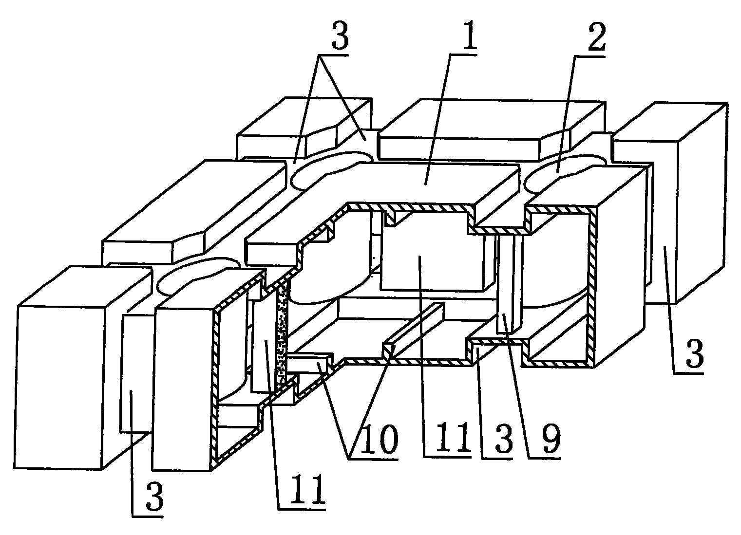
图17是本发明实施例17的结构示意图,在轻质构件1中有多个贯穿且相互平行的浇注孔洞2,外表面上设置有与浇注孔洞2的一端相交连通的凹槽3,轻质构件1上还设置有与浇注孔洞2平行的凹槽3,其所述的轻质构件1中还设置有加劲杆9、加强筋10和加劲肋11。Fig. 17 is a schematic structural view of Embodiment 17 of the present invention. There are a plurality of pouring
图18是本发明实施例18的结构示意图,在轻质构件1中有贯穿的浇注孔洞2,外表面上设置有与浇注孔洞2的一端相交连通的凹槽3,轻质构件1上还设置有与浇注孔洞2平行的凹槽3,其所述的轻质构件1上还设置有多个凸形模块12。Fig. 18 is a schematic structural view of Embodiment 18 of the present invention. There is a through
图19是本发明实施例19的结构示意图,在轻质构件1中有贯穿的浇注孔洞2,外表面上设置有与浇注孔洞2的一端相交连通的凹槽3,轻质构件1上还设置有与浇注孔洞2平行的凹槽3,其所述的轻质构件1上设置有定位构件13,图示定位构件13为定位块和定位脚。Fig. 19 is a schematic structural view of Embodiment 19 of the present invention. There is a through pouring
图20是本发明实施例20的结构示意图,在轻质构件1中有贯穿的浇注孔洞2,外表面上设置有与浇注孔洞2的一端相交连通的凹槽3,轻质构件1上还设置有与浇注孔洞2平行的凹槽3,其所述的轻质构件1上设置有连接构件14,图示连接构件14为承插管件。Fig. 20 is a schematic structural view of Embodiment 20 of the present invention. There is a through
图21是本发明实施例21的结构示意图,在轻质构件1中有贯穿的浇注孔洞2,外表面上设置有与浇注孔洞2的一端相交连通的凹槽3,轻质构件1上还设置有与浇注孔洞2平行的凹槽3,轻质构件1上设置有连接构件14,其多个轻质构件1通过连接构件14连接成成组轻质构件,图示连接构件14为杆件。Fig. 21 is a schematic structural view of
图22是本发明实施例22的结构示意图,在轻质构件1中有贯穿的浇注孔洞2,外表面上设置有与浇注孔洞2的一端相交连通的凹槽3,轻质构件1上还设置有与浇注孔洞2平行的凹槽3,其所述的轻质构件1伸出有挑板15,多个轻质构件1通过挑板15连成成组轻质构件。Fig. 22 is a schematic structural view of Embodiment 22 of the present invention. There is a through
(五)具体实施方式 (5) Specific implementation methods
下面结合附图和实施例对本发明作进一步的说明。The present invention will be further described below in conjunction with the accompanying drawings and embodiments.
本发明如附图所示,包括轻质构件1,其特征在于在轻质构件1中有至少一个贯穿上下竖向的浇注孔洞2,在轻质构件1外表面上有至少一条与浇注孔洞2的至少一端相交连通的凹槽3,在轻质构件1上有至少一条与浇注孔洞2平行的凹槽3,加强筋10设置在轻质构件内部的上壁和下壁上,所述的轻质构件1的至少一个面上叠合有叠合层8。各附图中,1为轻质构件,2为浇注孔洞,3为凹槽,以下各附图中,编号相同的,其说明相同。如图1所示,在轻质构件1中有贯穿的浇注孔洞2,外表面上设置有与浇注孔洞2的一端相交连通的凹槽3,其轻质构件1上还设置有与浇注孔洞2平行的凹槽3,图示为侧面上的凹槽3与浇注孔洞2平行。As shown in the accompanying drawings, the present invention includes a
本发明的特征还在于轻质构件1外表面上有至少一条与浇注孔洞2的至少一端相交连通的凹槽3。如图17、图18、图19、图20所示,轻质构件1外表面上有与浇注孔洞2的一端相交连通的凹槽3。The present invention is also characterized in that there is at least one
本发明的特征还在于轻质构件1上有至少一条与浇注孔洞2平行的凹槽3。如图17、图18、图19、图20所示,轻质构件1上有与浇注孔洞2平行的凹槽3。The invention is also characterized in that the
本发明的特征还在于在轻质构件1的至少一个拐角处设置有阴角4或倒角5或弧形角6。图2是本发明实施例2的结构示意图,在轻质构件1中有贯穿的浇注孔洞2,外表面上设置有与浇注孔洞2的一端相交连通的凹槽3,轻质构件1上还设置有与浇注孔洞2平行的凹槽3,其轻质构件1的拐角处设置有阴角4、倒角5和弧形角6。The present invention is also characterized in that at least one corner of the
本发明的特征还在于所述的轻质构件1上有至少一条凹槽3与阴角4或倒角5或弧形角6正交或斜交。图3是本发明实施例3的结构示意图,在轻质构件1中有贯穿的浇注孔洞2,外表面上设置有与浇注孔洞2的一端相交连通的凹槽3,轻质构件1上还设置有与浇注孔洞2平行的凹槽3,轻质构件1的拐角处设置有阴角4、倒角5和弧形角6,其轻质构件1上有凹槽3与阴角4和倒角5呈正交设置。The present invention is also characterized in that there is at least one
本发明的特征还在于所述的至少一条凹槽3与呈L形或U形布置的倒角5或弧形角6正交或斜交。图4是本发明实施例4的结构示意图,在轻质构件1中有贯穿的浇注孔洞2,外表面上设置有与浇注孔洞2的一端相交连通的凹槽3,轻质构件1上还设置有与浇注孔洞2平行的凹槽3,轻质构件1的拐角处设置有倒角5,其凹槽3与呈L形布置的倒角5呈正交设置。The present invention is also characterized in that the at least one
本发明的特征还在于所述的至少一条环胎凹槽3与阴角4或倒角5或弧形角6正交或斜交。图5是本发明实施例5的结构示意图,在轻质构件1中有贯穿的浇注孔洞2,外表面上设置有与浇注孔洞2的一端相交连通的凹槽3,轻质构件1上还设置有与浇注孔洞2平行的凹槽3,凹槽3为环胎凹槽,其环胎凹槽3与阴角4和倒角5呈正交设置。The present invention is also characterized in that the at least one
本发明的特征还在于所述的至少一条凹槽3与环胎阴角4或倒角5或弧形角6正交或斜交。图6是本发明实施例6的结构示意图,在轻质构件1中有贯穿的浇注孔洞2,外表面上设置有与浇注孔洞2的一端相交连通的凹槽3,轻质构件1上还设置有与浇注孔洞2平行的凹槽3,轻质构件1的拐角处设置有环胎阴角4,其凹槽3与环胎阴角4呈正交设置。The present invention is also characterized in that the at least one
本发明的特征还在于所述的至少二条平行的凹槽3与环胎阴角4或倒角5或弧形角6正交或斜交。图7是本发明实施例7的结构示意图,在轻质构件1中有贯穿的浇注孔洞2,外表面上设置有与浇注孔洞2的一端相交连通的凹槽3,轻质构件1上还设置有与浇注孔洞2平行的凹槽3,轻质构件1的拐角处设置有环胎阴角4,其二条平行的凹槽3与环胎阴角4呈正交设置。The present invention is also characterized in that the at least two
本发明的特征还在于所述的至少二条正交的凹槽3与环胎阴角4或倒角5或弧形角6正交或斜交。图8是本发明实施例8的结构示意图,在轻质构件1中有贯穿的浇注孔洞2,外表面上设置有与浇注孔洞2的一端相交连通的凹槽3,轻质构件1上还设置有与浇注孔洞2平行的凹槽3,轻质构件1的拐角处设置有环胎阴角4,其二条正交的凹槽3与环胎阴角4呈正交设置。The present invention is also characterized in that the at least two
本发明的特征还在于所述的至少一条与孔洞2相交的凹槽3与环胎阴角4或倒角5或弧形角6正交或斜交。图9是本发明实施例9的结构示意图,在轻质构件1中有贯穿的浇注孔洞2,外表面上设置有与浇注孔洞2的一端相交连通的凹槽3,轻质构件1上还设置有与浇注孔洞2平行的凹槽3,轻质构件1的拐角处设置有阴角4、倒角5和弧形角6,其与孔洞2相交的凹槽3与环胎阴角4呈正交设置。The present invention is also characterized in that the at least one
本发明的特征还在于所述的轻质构件1的至少两个面上有凹槽3与环胎阴角4或倒角5或弧形角6正交或斜交。图10是本发明实施例10的结构示意图,在轻质构件1中有贯穿的浇注孔洞2,外表面上设置有与浇注孔洞2的一端相交连通的凹槽3,轻质构件1上还设置有与浇注孔洞2平行的凹槽3,轻质构件1的拐角处设置有阴角4和弧形角6,其四个面上均有凹槽3与环胎阴角4和环胎弧形角6呈正交设置。The present invention is also characterized in that there are
本发明的特征还在于所述的孔洞2的两端的凹槽3与环胎阴角4或倒角5或弧形角6正交或斜交。如图10所示,在轻质构件1中有贯穿的浇注孔洞2,外表面上设置有与浇注孔洞2的一端相交连通的凹槽3,轻质构件1上还设置有与浇注孔洞2平行的凹槽3,轻质构件1的拐角处设置有阴角4和弧形角6,四个面均上有凹槽3与环胎阴角4和环胎弧形角6呈正交设置,其所述的孔洞2的两端的凹槽3与环胎阴角4和环胎弧形角6呈正交设置。The present invention is also characterized in that the
本发明的特征还在于所述的倒角5或弧形角6自身或相互大小有变化,或者倒角5或弧形角6为折线形、曲线形、台阶形。如图13所示,倒角5为折线形倒角。The present invention is also characterized in that the size of the
本发明的特征还在于所述的凹槽3或阴角4自身或相互大小有变化,或者凹槽3或阴角4为折线形、曲线形、台阶形。如图13所示,凹槽3为台阶形凹槽。The present invention is also characterized in that the
本发明的特征还在于所述的至少两个以上的孔洞2平行。图11是本发明实施例11的结构示意图,在轻质构件1中有贯穿的浇注孔洞2,外表面上设置有与浇注孔洞2的一端相交连通的凹槽3,轻质构件1上还设置有与浇注孔洞2平行的凹槽3,其所述的孔洞2设置有4个,4个孔洞2相互平行布置。The present invention is also characterized in that the at least two or
本发明的特征还在于所述的孔洞2的一端或两端为喇叭形或者台阶形。图12是本发明实施例12的结构示意图,在轻质构件1中有4个贯穿的相互平行的浇注孔洞2,外表面上设置有与浇注孔洞2的一端相交连通的凹槽3,轻质构件1上还设置有与浇注孔洞2平行的凹槽3,其所述的孔洞2的两端为喇叭形。The present invention is also characterized in that one or both ends of the
本发明的特征还在于所述的凹槽3在轻质构件1表面呈平行或正交或斜交布置。如图12所示,在轻质构件1中有4个贯穿的相互平行的浇注孔洞2,外表面上设置有与浇注孔洞2的一端相交连通的凹槽3,轻质构件1上还设置有与浇注孔洞2平行的凹槽3,孔洞2的两端为喇叭形,其所述的凹槽3在轻质构件1表面呈平行、正交布置。The present invention is also characterized in that the
本发明的特征还在于所述的轻质构件1的壁体内含有增强物7,或者还有增强物7露出。图13是本发明实施例13的结构示意图,在轻质构件1中有贯穿的浇注孔洞2,外表面上设置有与浇注孔洞2的一端相交连通的凹槽3,轻质构件1上还设置有与浇注孔洞2平行的凹槽3,其所述的轻质构件1的壁体内含有增强物7,图示增强物7为纤维网格布。The present invention is also characterized in that the wall of the
本发明的特征还在于所述的轻质构件1的至少一个面上叠合有叠合层8。图14是本发明实施例14的结构示意图,在轻质构件1中有贯穿的浇注孔洞2,外表面上设置有与浇注孔洞2的一端相交连通的凹槽3,轻质构件1上还设置有与浇注孔洞2平行的凹槽3,其所述的轻质构件1上叠合有叠合层8,图示叠合层8设置于轻质构件1的下底面上。The present invention is also characterized in that a laminated layer 8 is laminated on at least one surface of the
本发明的特征还在于所述的轻质构件1为实心轻质构件或者空心轻质构件。图15是本发明实施例15的结构示意图,在轻质构件1中有贯穿的浇注孔洞2,外表面上设置有与浇注孔洞2的一端相交连通的凹槽3,轻质构件1上还设置有与浇注孔洞2平行的凹槽3,其所述的轻质构件1为实心轻质构件。The present invention is also characterized in that the
本发明的特征还在于所述的实心轻质构件1为实心轻质胎体或硬壳实心轻质胎体。图16是本发明实施例16的结构示意图,在轻质构件1中有贯穿的浇注孔洞2,外表面上设置有与浇注孔洞2的一端相交连通的凹槽3,轻质构件1上还设置有与浇注孔洞2平行的凹槽3,轻质构件1为实心轻质构件,其所述的实心轻质构件1为硬壳实心轻质胎体。The present invention is also characterized in that the solid
本发明的特征还在于所述的轻质构件1中设置有加劲杆9、加强筋10、加劲肋11中的至少一个,或者加劲杆9、加强筋10、加劲肋11中的至少一个露出轻质构件1外,或者还有增强物7露出。图17是本发明实施例17的结构示意图,在轻质构件1中有多个贯穿且相互平行的浇注孔洞2,外表面上设置有与浇注孔洞2的一端相交连通的凹槽3,轻质构件1上还设置有与浇注孔洞2平行的凹槽3,其所述的轻质构件1中还设置有加劲杆9、加强筋10和加劲肋11。The present invention is also characterized in that at least one of the stiffeners 9, ribs 10, and stiffeners 11 is provided in the
本发明的特征还在于所述的轻质构件1上设置有凸形模块12。图18是本发明实施例18的结构示意图,在轻质构件1中有贯穿的浇注孔洞2,外表面上设置有与浇注孔洞2的一端相交连通的凹槽3,轻质构件1上还设置有与浇注孔洞2平行的凹槽3,其所述的轻质构件1上还设置有多个凸形模块12。The present invention is also characterized in that the said
本发明的特征还在于所述的轻质构件1上设置有定位构件13。图19是本发明实施例19的结构示意图,在轻质构件1中有贯穿的浇注孔洞2,外表面上设置有与浇注孔洞2的一端相交连通的凹槽3,轻质构件1上还设置有与浇注孔洞2平行的凹槽3,其所述的轻质构件1上设置有定位构件13,图示定位构件13为定位块和定位脚。The present invention is also characterized in that a positioning
本发明的特征还在于所述的轻质构件1上设置有连接构件14,或者多个轻质构件1通过连接构件14连接成成组轻质构件。图20是本发明实施例20的结构示意图,在轻质构件1中有贯穿的浇注孔洞2,外表面上设置有与浇注孔洞2的一端相交连通的凹槽3,轻质构件1上还设置有与浇注孔洞2平行的凹槽3,其所述的轻质构件1上设置有连接构件14,图示连接构件14为承插管件。图21是本发明实施例21的结构示意图,在轻质构件1中有贯穿的浇注孔洞2,外表面上设置有与浇注孔洞2的一端相交连通的凹槽3,轻质构件1上还设置有与浇注孔洞2平行的凹槽3,轻质构件1上设置有连接构件14,其多个轻质构件1通过连接构件14连接成成组轻质构件,图示连接构件14为杆件。The present invention is also characterized in that the connecting
本发明的特征还在于所述的轻质构件1伸出有挑板15,多个轻质构件1通过挑板15连成成组轻质构件。图22是本发明实施例22的结构示意图,在轻质构件1中有贯穿的浇注孔洞2,外表面上设置有与浇注孔洞2的一端相交连通的凹槽3,轻质构件1上还设置有与浇注孔洞2平行的凹槽3,其所述的轻质构件1伸出有挑板15,多个轻质构件1通过挑板15连成成组轻质构件。The present invention is also characterized in that the
本发明的特征还在于所述的轻质构件1上设置有搬运件16。如图22所示,在轻质构件1中有贯穿的浇注孔洞2,外表面上设置有与浇注孔洞2的一端相交连通的凹槽3,轻质构件1上还设置有与浇注孔洞2平行的凹槽3,轻质构件1伸出有挑板15,多个轻质构件1通过挑板15连成成组模壳构件,其所述的轻质构件1上设置有搬运件16,图示搬运件16为提手。The present invention is also characterized in that the said
本发明实施时,先拌制水泥砂浆,在内设凸条的模具内制作一层水泥砂浆一层纤维网格布(或钢丝网),再一层水泥砂浆的多层叠合的带孔洞2模腔的开口胎体,在其凝结硬化后,脱去外模制得开口胎模,然后将其扣合于尚未凝结硬化的钢丝网水泥砂浆下底面上接合密实,待凝结硬化后,即得轻质构件。During the implementation of the present invention, cement mortar is first mixed, and one deck of cement mortar and one deck of fiber mesh cloth (or steel wire mesh) are made in the mold with convex lines inside, and the multi-layered 2 molds with holes of one deck of cement mortar are laminated. The open carcass of the cavity, after it is set and hardened, the outer mold is taken off to make the open carcass, and then it is fastened on the bottom surface of the steel mesh cement mortar that has not yet set and hardened, and the joint is dense. quality components.
Claims (28)
Priority Applications (1)
| Application Number | Priority Date | Filing Date | Title |
|---|---|---|---|
| CNB2006101372581A CN100545373C (en) | 2003-11-02 | 2003-11-02 | A lightweight component for concrete filling |
Applications Claiming Priority (1)
| Application Number | Priority Date | Filing Date | Title |
|---|---|---|---|
| CNB2006101372581A CN100545373C (en) | 2003-11-02 | 2003-11-02 | A lightweight component for concrete filling |
Related Parent Applications (1)
| Application Number | Title | Priority Date | Filing Date |
|---|---|---|---|
| CN 200310103956 Division CN1280501C (en) | 2003-11-02 | 2003-11-02 | A lightweight component for concrete filling |
Publications (2)
| Publication Number | Publication Date |
|---|---|
| CN1940224A CN1940224A (en) | 2007-04-04 |
| CN100545373C true CN100545373C (en) | 2009-09-30 |
Family
ID=37958714
Family Applications (1)
| Application Number | Title | Priority Date | Filing Date |
|---|---|---|---|
| CNB2006101372581A Expired - Fee Related CN100545373C (en) | 2003-11-02 | 2003-11-02 | A lightweight component for concrete filling |
Country Status (1)
| Country | Link |
|---|---|
| CN (1) | CN100545373C (en) |
-
2003
- 2003-11-02 CN CNB2006101372581A patent/CN100545373C/en not_active Expired - Fee Related
Also Published As
| Publication number | Publication date |
|---|---|
| CN1940224A (en) | 2007-04-04 |
Similar Documents
| Publication | Publication Date | Title |
|---|---|---|
| CN100549314C (en) | A kind of light component for concrete filling | |
| CN100501041C (en) | A lightweight component for concrete filling | |
| CN100535290C (en) | Light constructural component for filling concrete | |
| CN100467742C (en) | A lightweight tire mold component for cast-in-place concrete | |
| CN1321248C (en) | A lightweight tire mold member for concrete filling | |
| CN100501067C (en) | A lightweight tire mold member for concrete filling | |
| CN100434611C (en) | A lightweight tire mold component for cast-in-place concrete | |
| CN1296585C (en) | A lightweight component for concrete filling | |
| CN1325736C (en) | Concrete filled light mould member | |
| CN100545377C (en) | A lightweight tire mold component for cast-in-place concrete | |
| CN100501046C (en) | A lightweight tire mold member for concrete filling | |
| CN100476122C (en) | A lightweight tire mold component for cast-in-place concrete | |
| CN100577947C (en) | A cavity formwork component for cast-in-place concrete | |
| CN1854401B (en) | Cast-in-situs concrete board | |
| CN100564743C (en) | A kind of concrete hollow board | |
| CN100535272C (en) | Light mould member for cast-in-situ concrete | |
| CN100414053C (en) | Hollow shuttering member | |
| CN100587189C (en) | A lightweight tire mold component for cast-in-place concrete | |
| CN100570091C (en) | A cavity formwork component for cast-in-place concrete | |
| CN100501022C (en) | A lightweight tire mold component for cast-in-place concrete | |
| CN100458047C (en) | Component of moulding bed in lightweight in use for pouring concrete in site | |
| CN100467740C (en) | A cavity formwork member | |
| CN100414056C (en) | Hollow shuttering member | |
| CN100535362C (en) | Cavity member for hollow slab | |
| CN1289767C (en) | A lightweight tire mold member for concrete filling |
Legal Events
| Date | Code | Title | Description |
|---|---|---|---|
| C06 | Publication | ||
| PB01 | Publication | ||
| C10 | Entry into substantive examination | ||
| SE01 | Entry into force of request for substantive examination | ||
| C14 | Grant of patent or utility model | ||
| GR01 | Patent grant | ||
| ASS | Succession or assignment of patent right |
Owner name: HUNAN QIU ZEYOU PATENT STRATEGIC PLANNING CO., LTD Free format text: FORMER OWNER: QIU ZEYOU Effective date: 20101012 |
|
| C41 | Transfer of patent application or patent right or utility model | ||
| COR | Change of bibliographic data |
Free format text: CORRECT: ADDRESS; FROM: 410011 28/F, SHUNTIAN CITY, NO.59, FURONG MIDDLE ROAD (SECOND SECTION), CHANGSHA CITY, HUNAN PROVINCE TO: 410205 JUXING INDUSTRIAL BASE, NO.8, LUJING ROAD, CHANGSHA HIGH-TECH. DEVELOPMENT AREA, YUELU DISTRICT, CHANGSHA CITY, HUNAN PROVINCE |
|
| TR01 | Transfer of patent right |
Effective date of registration: 20101012 Address after: 410205, Hunan Changsha Changsha hi tech Development Zone, Yuelu District Road, No. 8 star industry base Patentee after: Hunan Qiuzeyou Patent Strategy Planning Co., Ltd. Address before: 410011 Hunan province Changsha Furong Road two section 59 Suncheon City 28 floor Patentee before: Qiu Zeyou |
|
| CF01 | Termination of patent right due to non-payment of annual fee |
Granted publication date: 20090930 Termination date: 20141102 |
|
| EXPY | Termination of patent right or utility model |