CN100544985C - The banded press strip of vehicle interior and use the hermetically-sealed construction of inner banded press strip - Google Patents
The banded press strip of vehicle interior and use the hermetically-sealed construction of inner banded press strip Download PDFInfo
- Publication number
- CN100544985C CN100544985C CNB031566820A CN03156682A CN100544985C CN 100544985 C CN100544985 C CN 100544985C CN B031566820 A CNB031566820 A CN B031566820A CN 03156682 A CN03156682 A CN 03156682A CN 100544985 C CN100544985 C CN 100544985C
- Authority
- CN
- China
- Prior art keywords
- assembled portion
- press strip
- vehicle interior
- trim board
- banded press
- Prior art date
- Legal status (The legal status is an assumption and is not a legal conclusion. Google has not performed a legal analysis and makes no representation as to the accuracy of the status listed.)
- Expired - Fee Related
Links
Images


Classifications
-
- B—PERFORMING OPERATIONS; TRANSPORTING
- B60—VEHICLES IN GENERAL
- B60J—WINDOWS, WINDSCREENS, NON-FIXED ROOFS, DOORS, OR SIMILAR DEVICES FOR VEHICLES; REMOVABLE EXTERNAL PROTECTIVE COVERINGS SPECIALLY ADAPTED FOR VEHICLES
- B60J10/00—Sealing arrangements
- B60J10/70—Sealing arrangements specially adapted for windows or windscreens
- B60J10/74—Sealing arrangements specially adapted for windows or windscreens for sliding window panes, e.g. sash guides
- B60J10/75—Sealing arrangements specially adapted for windows or windscreens for sliding window panes, e.g. sash guides for sealing the lower part of the panes
-
- B—PERFORMING OPERATIONS; TRANSPORTING
- B60—VEHICLES IN GENERAL
- B60J—WINDOWS, WINDSCREENS, NON-FIXED ROOFS, DOORS, OR SIMILAR DEVICES FOR VEHICLES; REMOVABLE EXTERNAL PROTECTIVE COVERINGS SPECIALLY ADAPTED FOR VEHICLES
- B60J10/00—Sealing arrangements
- B60J10/15—Sealing arrangements characterised by the material
- B60J10/16—Sealing arrangements characterised by the material consisting of two or more plastic materials having different physical or chemical properties
-
- B—PERFORMING OPERATIONS; TRANSPORTING
- B60—VEHICLES IN GENERAL
- B60J—WINDOWS, WINDSCREENS, NON-FIXED ROOFS, DOORS, OR SIMILAR DEVICES FOR VEHICLES; REMOVABLE EXTERNAL PROTECTIVE COVERINGS SPECIALLY ADAPTED FOR VEHICLES
- B60J10/00—Sealing arrangements
- B60J10/20—Sealing arrangements characterised by the shape
- B60J10/26—Sealing arrangements characterised by the shape characterised by the surface shape
- B60J10/265—Sealing arrangements characterised by the shape characterised by the surface shape the surface being primarily decorative
-
- B—PERFORMING OPERATIONS; TRANSPORTING
- B60—VEHICLES IN GENERAL
- B60J—WINDOWS, WINDSCREENS, NON-FIXED ROOFS, DOORS, OR SIMILAR DEVICES FOR VEHICLES; REMOVABLE EXTERNAL PROTECTIVE COVERINGS SPECIALLY ADAPTED FOR VEHICLES
- B60J10/00—Sealing arrangements
- B60J10/30—Sealing arrangements characterised by the fastening means
Landscapes
- Engineering & Computer Science (AREA)
- Mechanical Engineering (AREA)
- Seal Device For Vehicle (AREA)
Abstract
The banded press strip of a kind of vehicle interior, edge of opening mounted inside along the vehicle lifting vehicle window, wherein vehicle has the inner panel and the trim board of car door, and trim board is connected on the inner panel of car door and has downward bead part, and described downward bead part is stretched out from the interior location of trim board outer end.The banded press strip of this vehicle interior comprises: assembled portion is connected to car body; And sealing lip, form with the assembled portion outside is whole, with the wind glass inside face Elastic Contact of lifting vehicle window.Assembled portion has a upward opening groove, can divide assembling with downward lip portions.Assembled portion includes the outer assembled portion of upward opening groove, and the in-to-in assembled portion that is positioned at outer assembled portion.The oriented under shed groove of interior assembled portion is used to hold the top edge bead part of inner plate of car door.The upper shed groove is arranged on the inside of trim board outer end.The upper shed groove can hold the exterior downward bead part of the top edge bead part that is positioned at inner plate of car door.
Description
Technical field
The present invention relates to a kind of banded press strip of vehicle interior of vehicle window edge of opening assembling of the inner plate of car door along the car door that drop window glass is arranged, drop window glass moves in the non-internal vertical of opening door or unlatching door of door skin with vehicle and inner plate of car door, and relates to the hermetically-sealed construction that uses the banded press strip of identical inner.The banded press strip of this vehicle interior is (under some situation, hereinafter be called " banded press strip " simply) by occupying or covering in the vehicle window edge of opening of inner plate of car door and the gap between the wind glass to shield this gap, and also by with the Elastic Contact of drop window glass sealing this gap, and then can be used for anti-sealing and dust and enter vehicle inside from the outside of vehicle.
Background technology
About banded press strip and its mounting structure a lot of the proposal arranged.So, as up-to-date banded press strip structure, from improving the angle of safety, for example, must avoid baby's finger when falling drop window glass, to be clamped such danger by wind glass, and ornamental angle, wish to reduce the gap between wind glass inside face and the vehicle interior sidecar gating element.
In order to satisfy above-mentioned needs, if banded press strip near the inner surface side of wind glass, the gap between them can be reduced, but meanwhile the sealing lip of banded press strip also near wind glass.Therefore, sealing lip very closely contacts with the inside face of wind glass, thereby the slip drag increases when wind glass moves up and down.In contrast, resist the increase of the slip drag of wind glass inside face in order to suppress sealing lip, if in the length that keeps shortening under the very little situation in gap sealing lip, so owing to for example installation error of wind glass, the effect of the accumulated errors such as shift position deviation when wind glass rises, sealing lip can't contact reliably with wind glass.Thereby, caused the such shortcoming of leak tightness decline.
Summary of the invention
An object of the present invention is to provide a kind of banded press strip, it can keep under the situation of leak tightness not increasing the slip drag, reduces the gap between wind glass inside face and the vehicle interior side car door element, and the mounting structure that it is provided.
For achieving this end, the invention provides the banded press strip of a kind of vehicle interior, mounted inside along the edge of opening of vehicle lifting vehicle window, wherein vehicle has the inner panel and the trim board of car door, trim board is connected on the inner panel of car door and has a downward bead part, and described downward bead part is stretched out from the interior location of trim board outer end.The banded press strip of vehicle interior comprises: assembled portion is connected to car body; Sealing lip forms with the outside of assembled portion is whole, with the wind glass inside face Elastic Contact of lifting vehicle window; Wherein assembled portion has a upward opening groove, can divide assembling with downward lip portions.Assembled portion comprises an outer assembled portion, and outer assembled portion has the upward opening groove, and an interior assembled portion, and interior assembled portion is positioned at the inside of outer assembled portion; The oriented under shed groove of wherein interior assembled portion is used to hold the top edge bead part of inner plate of car door; And wherein the upper shed groove is arranged on the inside of trim board outer end; And the upper shed groove can hold the exterior downward bead part of the top edge bead part that is positioned at inner plate of car door.
According to the present invention, the downward bead of stretching out downwards partly is inserted under the state of the upward opening groove that is formed in the assembled portion, and the assembled portion of inner banded press strip is assembled on the trim board.The bead part is stretched out from the inner side slightly rather than the external side end position of trim board downwards.Thereby, can reduce as the end edge of the trim board of inner car door element and the gap between the wind glass inside face, and can not shorten the extension elongation of sealing lip.As a result, the finger that might eliminate baby for example etc. is sandwiched in danger such in the gap, and improves ornamental.And, can obtain the extension elongation of required sealing lip, and not need to shorten the extension elongation of sealing lip.As a result, can guarantee the elastic deformation surplus of sealing lip fully with respect to wind glass.The slip drag does not increase in the wind glass uphill process.Leak tightness does not descend.
According to the present invention, two different pieces (assembled portion), that is, the top edge bead part that constitutes the downward bead part of trim board of inner car door element and inner plate of car door is held by upward opening groove that is set to outer assembled portion and the downward open groove that is set to interior assembled portion respectively.Thereby, even when drop window glass owing to the slip drag that acts on the sealing lip has an application force that makes banded press strip self vertical shifting, but moving of banded press strip can be by any being prevented in top two different assembled portion.As a result, banded press strip will not partly come off from the downward bead of trim board.And, because banded press strip is assembled to and constitutes the car door element and along be separated by two different assembled portion of preset distance placement of the inside with outside direction of vehicle, only be assembled to an assembled portion (the downward bead part of trim board) with banded press strip and compare, can prevent that banded press strip is offset at the rigging position of the outside and inside direction of vehicle.Thereby can prevent that banded press strip from sending in the same direction crackling.
The upward opening groove preferably is provided with at least one clamping lip and is used to clamp downward bead part to prevent that it from coming off.
According to the present invention, the assembled portion of formation car door element is clamped by the clamping lip of the open groove that is arranged in banded press strip assembled portion.Thereby banded press strip is difficult to move with respect to assembled portion on the inward-outward direction of vertical direction and vehicle.Thereby, can prevent that banded press strip from coming off from assembled portion, and banded press strip draws sound along the noise made in coughing or vomiting of vehicle interior side lateral direction.
Open groove preferably also has at least one clamping lip to be used to clamp top edge bead part to prevent that it from coming off downwards.
According to the present invention, owing to clamp top edge bead part to prevent that its clamping lip that comes off is arranged in downward open groove, banded press strip is difficult to move with respect to assembled portion on the inward-outward direction of vertical direction and vehicle.
The banded press strip of vehicle interior preferably also comprises: the cloth extrusion that protrudes upward from the assembled portion outside; Wherein the extruding when downward lip portions branch is assembled to the upward opening groove of cloth extrusion covers the end portion of the cloth sheet on trim board surface.
According to the present invention, when making the trim board assembling in the upward opening groove that partly is inserted into by downward bead on the assembled portion that is formed on the banded press strip with trim board, when maybe making the trim board assembling in the upward opening groove when partly be inserted into the assembled portion that is formed in banded press strip (being fixed in the top edge bead part of inner plate of car door) by downward bead on trim board, the end portion that is assembled to the cloth on trim board surface be subjected to being set to the assembled portion outside the cloth extrusion extruding and protrude upward, thereby the end portion that can prevent cloth is from the trim board surfacial spalling.
Assembled portion preferably has a polarizing slot, partly from wherein crossing; And this polarizing slot can match with the locating flange that stretches out downwards from the trim board rear surface.
According to the present invention, because under the state that banded press strip is longitudinally located, banded press strip is fixed on the trim board, thereby can prevent to produce between them along car body relative displacement longitudinally.
Optimal way is that the thickness of locating flange is littler than the width of polarizing slot.
Owing to can form relative broad when otch adds man-hour its width on banded press strip, thereby the processing of otch can be than being easier to.On the contrary and since when trim board by injection mo(u)lding during moulding, locating flange can be narrow, thereby can prevent to form " indenture " that is produced owing to locating flange on the surface of trim board.And because the thickness of locating flange is littler than the groove width of otch, the assembly manipulation of banded press strip and trim board can be easy to.
Optimal way is, polarizing slot comprises along assembled portion two polarizing slots that preset distance arranges of vertically being separated by at least; Locating flange comprises at least two locating flanges that will be assembled in the polarizing slot; And in the polarizing slot two so form, promptly when two in the locating flange be assembled in the polarizing slot two when middle two apparent surface in the locating flange contact with two inner surface in the polarizing slot.
Optimal way is, polarizing slot comprises along assembled portion two polarizing slots that preset distance arranges of vertically being separated by at least; Locating flange comprises at least two polarizing slots in two that will be assembled in the polarizing slot; And in the polarizing slot two so form, promptly when two in the locating flange be assembled in the polarizing slot two when middle two outer surface in the locating flange contact with two outer surface in the adjacent positioned otch.
The banded press strip of vehicle interior preferably also comprises: along vertical embedding core component wherein of assembled portion, core component is made by board-like material, and the expansion drag (expansionresistance) and the rigidity of material are all big than assembled portion; Wherein the shape of cross section of core component is similar substantially with the part of assembled portion at least.
According to the present invention, the expansion of banded press strip and shrink can prevent and the intensity of assembled portion also can increase.As a result, the banded press strip assembled condition that is assembled to trim board can be stablized.
Assembled portion is preferably made by thermoplastic elastic material.
According to the present invention, because the assembled portion of being made by thermoplastic elastic material has certain elasticity, assembled portion and " assembling " that be assembled between the part are improved.Therefore, banded press strip be assembled to be assembled the part assembly performance can strengthen.
Sealing lip be preferably by being fusion welded to assembled portion, and makes than softer, the more resilient material of assembled portion.
According to the present invention, given sealing lip suitable elasticity.As a result, sealing lip and wind glass Elastic Contact, thereby the leak tightness between wind glass and the sealing lip can improve.
The invention provides a kind of banded press strip of vehicle interior of inboard assembling of the edge of opening along the lifting vehicle window, the banded press strip of vehicle interior comprise one with car body bonded assembly assembled portion, and whole formation in the outside with assembled portion with the sealing lip of the inside face Elastic Contact of the wind glass of lifting vehicle window; And a trim board that is placed in lifting vehicle window inboard, trim board has a downward bead part of stretching out from the interior location of its outer end; Wherein assembled portion has a upward opening groove, can divide assembling with downward lip portions; And the banded press strip of vehicle interior is connected on the trim board by downward bead partly being inserted into the upward opening part.
Assembled portion preferably includes an outer assembled portion, and it has unlatching groove upwards, and interior assembled portion, is positioned at the interior location of outer assembled portion; Outer assembled portion has a polarizing slot, partly from wherein crossing; Trim board has a locating flange, stretches out downwards from its rear surface; And when by locating flange is inserted into polarizing slot so that inner banded press strip when longitudinally locating, inner banded press strip is connected to downward bead part.
Accompanying drawing is described
The present invention can more easily describe with reference to accompanying drawing.
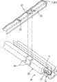
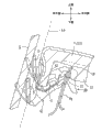
Fig. 1 is the lateral plan that the right front door of vehicle is shown, and when watching internally, banded press strip according to the present invention is assembled on it.
Fig. 2 illustrates the banded press strip that is in separated position and the cutaway view of trim board respectively.
Fig. 3 is the transparent view that the upper end part of banded press strip and trim board rear side is shown respectively.
Fig. 4 is along X among Fig. 1
1-X
1The cutaway view of the amplification of line.
Fig. 5 is along X among Fig. 1
2-X
2The cutaway view of the amplification of line.
Fig. 6 mainly illustrates the view that concerns between the locating flange thickness of the polarizing slot width of banded press strip and trim board.
The specific embodiment
Reference embodiment hereinafter carries out detailed explanation to the present invention.Fig. 1 shows the right front door of vehicle D, and when watching internally, banded press strip M according to the present invention is assembled on it.Fig. 2 illustrates the banded press strip M that is in separated position and the cutaway view of trim board T.Fig. 3 is the transparent view of a part that the upper part of banded press strip M and trim board T rear end side is shown respectively.Fig. 4 is along X among Fig. 1
1-X
1The cutaway view of the amplification of line.Fig. 5 is along X among Fig. 1
2-X
2The cutaway view of the amplification of line.Fig. 6 is the thickness (t of locating flange 57 of width (K) and trim board T that the polarizing slot 18 of banded press strip M mainly is shown
1) between the relation view.
At first, the part of the vehicle window opening B that is arranged on vehicle Qianmen D is described, illustrates then at the strip-shaped bands or the press strip M of car body fore-and-aft direction along the vehicle interior side edge of opening assembling of vehicle window opening B.Among Fig. 1, comprise inner plate of car door P (seeing Fig. 4 and Fig. 5) and door skin (not shown) by the open/close Qianmen D of hinge.The inside of window frame 41 is provided with a glass run channel (not shown) that is used to guide wind glass G rise and fall campaign, and its global shape is similar to a kind of " U " shape, and is parts of extending downwards from window frame 41.Lifting window W constructs in such a way: as wind glass G during along the leader up-and-down movement of glass run channel, vehicle window opening B completely or partially closes, and perhaps opens fully.The inside of inner plate of car door P is covered with trim board T, and trim board T is assembled on the inner plate of car door P by clip or clasp (not shown) etc., and is exposed to the inboard.Handrail 42 is assembled to the inner surface that is exposed to trim board T inboard.In this case, among Fig. 1, the door switch that 43 expressions are used for opening the door internally, 44 expression side mirror assembly openings.
Among Fig. 2, trim board T also is by very hard and the ABS resin of certain rigidity is arranged, the PP resin, or the materials similar injection mo(u)lding, so that its global approximation is an aspect.The rigging position of trim board T in the inboard is lower than the lower edge of vehicle window opening B.Downward bead part 52 integral body of stretching out downwards are set to its position a little towards the part of inboard, rather than are set to the vehicle outside end 51a of the cover part, top 51 on trim board T top.Because bead part 52 is set to above-mentioned position downwards, the distance (L between wind glass G inside face and the downward bead part 52
1) greater than the distance (L between the vehicle outside end (exactly, the vehicle outside end of cover part, top 51) of wind glass G inside face and trim board T
2) (see figure 2).As a result, this structure can guarantee to constitute enough elastic deformation surpluses of banded press strip M and sealing lip S described later.
As Fig. 3, Fig. 5 and shown in Figure 6, a plurality of contact flanges 53 be along on the rear surface of the whole cover part, top 51 that is set to trim board T of the predetermined distance of car body longitudinal interval, to stretch out downwards when the confined state.The vehicle interior side side of the downward bead part 52 of trim board T also is the same with aspect.Yet downwards the vehicle outside side of bead part 52 so forms, and promptly has only from the part of its lower end predetermined length to constitute mating surfaces 54, and mating surfaces 54 contacts with the inner wall surface that reaches upward opening groove 11 described later on being formed on banded press strip M.Step portion 55 is formed at the part higher than mating surfaces 54, to have the structure of a part that is inserted into banded press strip M.The surface coverage of trim board T cloth (skin-material) 56, is made by textiles or materials similar.One end 56a of the cloth 56 of vehicle outside almost reaches the step portion 55 on the vehicle outside side of downward bead part 52.In this case, have only the part of contact flange 53 to be shown in Fig. 3.
As shown in Figure 4 and Figure 5, trim board T and inner plate of car door P also are arranged in the downside of the lower edge of the vehicle window opening B that is lower than Qianmen D, and its layout also is assembled under the state of vehicle interior side at trim board T, make the top edge bead part Pa of inner plate of car door P be located immediately at cover part, top 51 below.The reinforcement plate 61 that inner plate of car door P comprises inner plate of car door main body 62 and is positioned at the main body outside. Parts 61,62 all with the same formation of flat board that is positioned at top edge bead part Pa, and by welding or similarly method connect together.
To Fig. 6 the banded press strip M of the downward bead part 52 that is assembled to trim board T and the top edge bead part Pa of inner plate of car door P are described below with reference to Fig. 2.Banded press strip M comprises a vehicle outside assembled portion 10, and assembled portion 10 has upward opening groove 11, and the downward bead part 52 of trim board T is inserted in the upward opening groove 11; And vehicle interior side assembled portion 20, assembled portion 20 oriented under shed grooves 21, the top edge bead part Pa of inner plate of car door P inserts this downward open groove 21.Two sealing lip S are integrally formed in the vehicle outside sidepiece of vehicle outside assembled portion 10.Two sealing lip S are provided with up and down separately respectively and point to and are tilted to.Therefore, the single-piece each several part of vehicle outside assembled portion 10 and vehicle interior side assembled portion 20 has constituted " assembled portion ", and assembled portion is assembled to the car door element as a whole, and the S shape after approximate lateral rotation of its shape of cross section formation.
In other words, a pair of clamping lip 12 that can elastic deformation, 12 are integrally formed on the vehicle interior side inner wall surface of the upward opening groove 11 that is formed in the vehicle outside assembled portion 10, to stretch out (with downward-sloping a little) towards the bottom side of upward opening groove 11 slightly.The fixedly lip 13 that elastic deformation also can take place also is to be integrally formed in by this way on the lower surface of upward opening groove 11, and promptly fixedly lip stretches out to point to the inner wall surface side of vehicle outside slightly.Cloth extruding lip 15 that can elastic deformation is set to the upper part (see figure 2) of the vehicle outside wall part 14 of the upward opening groove 11 that constitutes vehicle outside assembled portion 10, to extend upward.Prevent that the bolt that stretches out 16 that the downward bead part 52 (being inserted in the upward opening groove 11 of vehicle outside assembled portion 10) of trim board T comes off longitudinally is set to the connecting bridge between vehicle outside wall part 14 and the cloth extruding lip 15 continuously.In the present embodiment, be embedded in the vehicle outside assembled portion 10 preventing the single-piece elongation and to shrink by a metal tape being curved core component 17 that approximate U-shaped cross sectional shape obtained, and utilize its rigidity.In this case, from utilizing the viewpoint of rigidity, core component preferably resembles the S shape after the lateral rotation, and is similar with assembled portion.
A pair of clamping lip 22,22 that can elastic deformation also is integrally formed on the vehicle outside inner wall surface of downward open groove 21 of vehicle interior side assembled portion 20, is inclined upwardly with sensing.The vehicle outside wall part 23 of vehicle interior side assembled portion 20 also is used as the vehicle interior side wall part of vehicle outside assembled portion 10.The part of core component 17 embeds 23 li of vehicle outside wall parts to increase rigidity.In this case, core component also can embed in upper wall portion 24 and the vehicle interior side wall part 25.The vehicle interior side wall part 25 that constitutes vehicle interior side assembled portion 20 is bevelleds so that downwards the open side of open groove 21 to open width bigger, its global shape resembles a lip.
Described pair of seal lips S is a hermetic unit, this part can elastic deformation with the inside face Elastic Contact of wind glass G.Described thus pair of seal lips can prevent that sealing and dust enter vehicle inside.The rear surface side of sealing lip S and the inside face Elastic Contact of wind glass G.The rear surface side of sealing lip S is provided with cord velvebeen (being made by nylon fine hair etc.) etc.
Banded press strip M is by the material extrusion molding with caoutchouc elasticity, and with longitudinal extension, and core component 17 squeezes out together with the embedding state.Because material has caoutchouc elasticity, such as EPDM elastomeric materials such as (ethylene propylene diene rubbers), or thermoplastic elastic material (TPE) can be listed in preferred material.In addition, to the material of vehicle outside assembled portion 10 and vehicle interior side assembled portion 20 and the material of sealing lip S, it is more effective to adopt different materials to be used for banded press strip M respectively.In other words, preferably sealing lip S is by softness, and has the flexible good material to form, and assembled portion 10 and 20 is preferably formed by material harder than sealing lip S, good rigidly.When having selected such material, the assembly properties that banded press strip M is assembled to the car door element are more stable, and sealing lip S can touch the inside face of wind glass G and can not lose efficacy, so the sealing property between wind glass G and the sealing lip S is strengthened.As concrete material, each assembled portion 10 is formed by relative hard, rubber or the TPE bigger than sealing lip S rigidity with 20, and sealing lip S is by forming than the material softer of assembled portion 10 and 20 and the soft rubber or the soft TPE material of good springiness.So, two parts (assembled portion 10,20 and the sealing lip S) fusing by as above different materials forms connects, then by the Unitarily molded formation of coextrusion process.Thus, obtain assembled portion 10,20.
Respectively as Fig. 1, Fig. 3, Fig. 5 and shown in Figure 6, a pair of polarizing slot 18 are formed at the position near the rear end of the vehicle interior side assembled portion 20 that constitutes banded press strip M when confined state, the predetermined distance of longitudinally being separated by is partly to cross vehicle interior side assembled portion 20.In the cutaway view of the vehicle interior side assembled portion 20 of banded press strip M, a pair of polarizing slot 18 is formed at the whole zone of the vehicle interior side wall part 25 that constitutes vehicle interior side assembled portion 20, and almost half zone of upper wall portion 24.With contact flange 53 and separate, a pair of locating flange 57 is formed on the part of rear surface of last cover part 51 of trim board T, this part is corresponding with a pair of polarizing slot 18 of banded press strip M.In this manner, under polarizing slot 18 is set to situation near the rear end of banded press strip M, consider from the angle of whistle and sound insulation value, the rear end surface of banded press strip M preferably with glass run channel near-earth or closely contact as far as possible.Therefore, if polarizing slot 18 is positioned at the rear end side of banded press strip M, be difficult to locating bias takes place, such structure is best.
As shown in Figure 6, the width of polarizing slot 18 (K) is than the thickness (t of locating flange 57
1) want big, and the distance (L between the outer surface of a pair of polarizing slot 18
11) and the outer surface of a pair of locating flange 57 between distance (L
12) equal (L
11=L
12).
According to this dimensional structure, when making banded press strip M be assembled on the downward bead part 52 of trim board T in the upward opening groove 11 that is inserted into banded press strip M by downward bead part 52 with trim board T, under the lateral sulcus rooved face state of contact of a pair of polarizing slot 18 of the outer lateral side of a pair of locating flange 57 of trim board T and banded press strip M, locating flange 57 is inserted into 18 li of polarizing slots respectively, so that under the state of having determined in the fore-and-aft direction of vehicle location, banded press strip M can be assembled on the trim board T.Owing to be formed on the width (K) and the thickness (t that is formed on the locating flange 57 on the trim board T of the polarizing slot 18 on the banded press strip M
1) being set to above-mentioned size relationship, the bigger width when being formed on banded press strip M and going up owing to polarizing slot 18 like this makes polarizing slot processing than being easier to, and is assembled to trim board T when last as banded press strip M, and fitting operation (assembly manipulation) also is easy to.
In this case, in the above-described embodiments, when if the distance between the distance between the medial sulcus rooved face of a pair of polarizing slot 18 and the inner surface of a pair of locating flange 57 is equal to each other, just might realize such relation: the inner surface of a pair of locating flange 57 contacts the medial sulcus rooved face of a pair of polarizing slot 18 respectively, and the locating flange 57 of trim board T is inserted into respectively in the polarizing slot 18 of banded press strip M.
Thickness (the t of locating flange 57
1) with the thickness (t of the normal part of trim board T
0) such relation: t arranged
1=(1/3~2/3) t
0In this manner, if the thickness (t of locating flange 57
1) less than the thickness (t of the normal part of trim board T
0), can have such advantage: when trim board T by injection mo(u)lding during moulding, can prevent because the difference of shrinkage percentage and on the surface of trim board T, produce " indenture " during the resin cooling.If the thickness (t of the thickness of contact flange 53 and the normal part of trim board T
0) also have above-mentioned relation, also can prevent face side generation " depression " at the contact flange 53 of trim board T.
So, the banded press strip M with said structure is assembled on the trim board T of the door panel that constitutes Qianmen D.Two kinds of assembly methods are arranged, select wherein a kind of by the merits and demerits of studying these two kinds of methods respectively.A kind of assembly method is such: at first banded press strip M is assembled to trim board T, and the top edge bead part Pa that constitutes the inner plate of car door P of door panel then is inserted into 21 li of the downward open groove of the banded press strip M that is assembled to trim board T.Another kind of assembly method is such: at first the top edge bead part Pa of the inner plate of car door P by will constituting door panel is inserted into 21 li of the downward open groove of banded press strip M, so that banded press strip M is assembled on the inner plate of car door P, the downward bead part 52 of trim board T is inserted into 11 li of the upward opening grooves of banded press strip M then.According to the fwd method, when banded press strip M is assembled on the trim board T, at first trim board T is reversed, the downward bead part 52 of trim board T relatively is inserted into 11 li of the upward opening grooves of banded press strip M from the rear surface side of trim board T then, meanwhile, the polarizing slot 18 that makes banded press strip M matches with the position of the locating flange 57 of trim board T.Therefore, can obtain such advantage: the assembly manipulation that banded press strip M is assembled to trim board T is easy to.
So, according to any assembly method, be assembled at banded press strip M under the state of trim board T (trim board T constitutes the inside of the vehicle window opening B of door panel), as shown in Figure 4 and Figure 5, the downward bead part 52 of trim board T can be inserted into 11 li of the upward opening grooves of banded press strip M, and the top edge bead part Pa of inner plate of car door P also can be inserted into 21 li of the downward open groove of banded press strip M.Under above-mentioned state, a pair of locating flange 57 of trim board T also is inserted into 18 li of a pair of polarizing slots of banded press strip M respectively so that banded press strip M with respect to trim board T at longitudinal register, as mentioned above.
Be assembled at banded press strip M under the state of downward bead part 52 of trim board T, a pair of promotion lip 12 contacts with the vehicle interior side side elastic of downward bead part 52, and fixedly lip 13 also with the rear surface Elastic Contact of downward bead part 52, the mating surfaces 54 that therefore is formed on the vehicle outside side of downward bead part 52 contacts with the vehicle outside medial surface of the upward opening groove 11 of banded press strip M.Owing to be set to and stretch out bolt 16 on the vehicle outside inner surface that the position of step portion 55 of the vehicle outside side surface of downward bead part 52 is lower than the upward opening groove 11 that is formed on banded press strip M, thereby can prevent that downward bead part 52 from coming off for 11 li from the upward opening groove of banded press strip M.Be set to banded press strip M vehicle outside assembled portion 10 cloth extruding lip 15 also with the higher slightly part Elastic Contact in terminal 56a position than cloth 56 (covering on the surface of trim board T), peel off to prevent cloth 56.
On the contrary, in the part of the vehicle interior side assembled portion 20 of banded press strip M, be set to the vehicle outside side surface Elastic Contact of a pair of promotion lip 22 and the top edge bead part Pa of inner plate of car door P of the vehicle outside inner surface of downward open groove 21, top edge bead part Pa remains in and promotes between lip 22 and the vehicle interior side wall part 25 then.As shown in Figure 4, the a plurality of contact flanges 53 that are formed on 51 rear surfaces, cover part, top of trim board T contact with the upper wall portion 24 of vehicle interior side assembled portion 20, and the downward bead part 52 that defines trim board T thus is inserted into the insertion length of 11 li of upward opening grooves of the vehicle outside assembled portion 10 of banded press strip M.Then, the upper end face of the top edge bead part Pa of inner plate of car door P contacts with upper wall portion 24 inside faces of the vehicle interior side assembled portion 20 that constitutes banded press strip M.
Correspondingly, the downward bead part 52 of trim board T is inserted into 11 li of the upward opening grooves of the vehicle outside assembled portion 10 of banded press strip M, and the top edge bead part Pa of inner plate of car door P also is inserted into 21 li of the downward open groove of vehicle interior side assembled portion 20.As a result, bead part 52 and top edge bead part Pa firmly fix by the pushing action that promotes lip 12,22 respectively downwards.Elastic deformation also takes place in the pair of seal lips S that integral body is formed on the vehicle outside side surface of vehicle outside assembled portion 10 of banded press strip M, with the inside face Elastic Contact of wind glass G, and stably contacts with its inside face when rising wind glass G.Thereby pair of seal lips S can prevent that sealing and dust are entered the inside of vehicle by the outside of vehicle.
In this manner, banded press strip M is assembled to two different assembled portion (bead part 52 and top edge bead part Pa downwards) of door panel.Therefore, even one of slip drag effect owing to sealing lip S makes banded press strip M vertical shifting (exactly when rising wind glass G, the ascent direction of wind glass G) application force, above in two different assembled portion any one can accept this power, thereby prevented moving of banded press strip M.By the same token, the situation of an assembled portion (downwards bead part 52) that is assembled to door panel with banded press strip M is opposite, and banded press strip M along the rigging position skew of vehicle interior side-lateral direction (or being difficult to take place) can not take place.As a result, the confined state of banded press strip M structurally can obtain firmly.
As mentioned above, be integrally formed in downward bead part 52 on 51 rear surfaces, cover part, top of trim board T upper end and form the part that vehicle outside end (terminal edge) (exactly, the vehicle outside end of cover part, top 51) from trim board T is withdrawn into vehicle interior side a little.Therefore, the inside face of wind glass G and the distance (L between the bead part 52 downwards
1) greater than the distance (L between the inside face of wind glass G and the vehicle outside end of trim board T (exactly, the vehicle outside end of cover part, top 51)
2) (see figure 2).As a result, even the distance (L between the vehicle outside end of the inside face of wind glass G and trim board T
2) narrowly degree in the middle of can not being sandwiched in, the distance (L between the downward bead part 52 of the inside face of wind glass G and trim board T such as point to the baby
1) still can be greater than distance (L
2).Thereby the adjustment space (extension elongation of sealing lip S) of pair of seal lips S that can guarantee to constitute banded press strip M is enough big, and can guarantee that also the elastic deformation surplus of sealing lip S is enough big.Correspondingly, if the distance (L between the vehicle outside end of the inside face of wind glass G and trim board T
2) shorten (narrowing down), can prevent the minimizing of sealing force between sealing lip S and the wind glass G.As the distance (L between the vehicle outside end of the inside face of wind glass G and trim board T
2) result that shortens, the gap turn narrow that on this part, produces along the width over sides of car body direction, and meanwhile decorate properties (the good visual field) is also strengthened.In this case, among Fig. 4 and Fig. 5, dotted line L
0The vehicle outside end position of expression trim board T.
In the above-described embodiments, banded press strip M has two assembled portion 10,20 in vehicle outside and vehicle interior side, and banded press strip M is assembled to two parts of the top edge bead part Pa of the downward bead part 52 of trim board T and inner plate of car door P.Thereby as mentioned above, the assembling stability of banded press strip M can increase more.Yet, owing to have the banded press strip M of this spline structure, promptly only provide vehicle outside assembled portion 10 with upward opening groove 11, also can obtain principal advantages more of the present invention, so banded press strip M is also contained in the technical scope of the present invention.
In the above-described embodiments, explained that the present invention is applied to the example of the banded press strip M that constitutes the lifting window W that is set to vehicle Qianmen D.Certainly the present invention also can be applied to the banded press strip of other rising windows that constitute vehicle.
According to the present invention, assembled portion is provided with the upward opening groove, and described upward opening groove can divide with the downward lip portions of the trim board of the vehicle interior side that is assembled to the lifting window and cooperate.The bead part is stretched out downwards from the position that the vehicle outside end along the vehicle interior side direction from trim board is shifted slightly downwards.Trim board is assembled under the state of banded press strip partly being inserted into the upward opening groove by downward bead with trim board, can reduce as the trim board end edge of vehicle interior side car door element and the gap between the wind glass inside face, in addition, can guarantee between downward bead part and wind glass inside face, to have the adjustment space of enough sealing lips.As a result, the gap between trim board end edge and the wind glass inside face can keep very little, thereby the finger that can eliminate the baby etc. is sandwiched in the danger in the gap, and decorate properties can improve, and the actual extension elongation of sealing lip also can extend.As a result, can guarantee the enough elastic deformation surplus of sealing lip, and under the situation of the sealing property that does not reduce the rising wind glass, the slip drag does not increase yet with respect to wind glass.
Claims (35)
1. the banded press strip of a vehicle interior, described press strip is along the edge of opening mounted inside of vehicle lifting window, wherein vehicle has inner plate of car door and trim board, trim board is connected on the inner plate of car door and has a downward bead part, described downward bead part is stretched out from the interior location of trim board outer end, and the banded press strip of described vehicle interior comprises:
Assembled portion is connected to car body; And
Sealing lip forms with the assembled portion outside is whole, with the wind glass inside face Elastic Contact of drop window;
Wherein assembled portion has a upward opening groove, and described upward opening groove can divide assembling with downward lip portions;
Wherein assembled portion comprises an outer assembled portion, and outer assembled portion has the upward opening groove, and an interior assembled portion, and interior assembled portion is positioned at the inside of outer assembled portion;
The oriented under shed groove of wherein interior assembled portion is used to hold the top edge bead part of inner plate of car door; And
Wherein the upper shed groove is arranged on the inside of trim board outer end; And the upper shed groove can hold the exterior downward bead part of the top edge bead part that is positioned at inner plate of car door.
2. according to the banded press strip of the vehicle interior of claim 1,
Wherein the upward opening groove is provided with at least one and clamps lip, is used to clamp downward bead part to prevent that it from coming off.
3. according to the banded press strip of the vehicle interior of claim 1,
Wherein the upward opening groove is provided with at least one and clamps lip, is used to clamp downward bead part to prevent that it from coming off; And
Open groove is provided with at least one and clamps lip downwards, is used to clamp top edge bead part to prevent that it from coming off.
4. according to the banded press strip of the vehicle interior of claim 1, also comprise:
The cloth extrusion protrudes upward from the outside of assembled portion;
Wherein the cloth extrusion is when downward lip portions branch is assembled in the upward opening groove, and extruding covers the end of the cloth on trim board surface.
5. according to the banded press strip of the vehicle interior of claim 1,
Wherein assembled portion has a partly polarizing slot from wherein crossing; And
Polarizing slot can match with the locating flange that stretches out downwards from the rear surface of trim board.
6. according to the banded press strip of the vehicle interior of claim 5,
Wherein the thickness of locating flange is littler than the width of polarizing slot.
7. according to the banded press strip of the vehicle interior of claim 6,
Wherein polarizing slot comprises vertical at least two polarizing slots with arranged at predetermined intervals along assembled portion;
Locating flange comprises at least two locating flanges that are assembled in the polarizing slot; And
In the polarizing slot two so form, and promptly are assembled in the polarizing slot two when middle when two in the locating flange, and two apparent surface in the locating flange contacts with two inner surface in the polarizing slot.
8. according to the banded press strip of the vehicle interior of claim 6,
Wherein polarizing slot comprises along assembled portion vertically with predetermined spaced apart two polarizing slots at least;
Locating flange comprises at least two polarizing slots in two that are assembled in the polarizing slot; And
In the polarizing slot two so form, and promptly are assembled in the polarizing slot two when middle when two in the locating flange, and two outer surface in the locating flange contacts with two outer surface in the adjacent polarizing slot.
9. according to the banded press strip of the vehicle interior of claim 5, also comprise:
A core component, described core component along vertical embedding of assembled portion wherein, core component is made by board-like material, the expansion drag of material and rigidity all expansion drag and the rigidity than assembled portion material are big;
Wherein the shape of cross section of core component is similar with the shape of cross section of at least a portion of assembled portion in fact.
10. according to the banded press strip of the vehicle interior of claim 1,
Wherein assembled portion is made by thermoplastic elastic material.
11. according to the banded press strip of the vehicle interior of claim 1,
Wherein sealing lip be by being fusion welded to assembled portion, and makes than softer, the more resilient material of assembled portion.
12. according to the banded press strip of the vehicle interior of claim 1, wherein the upper shed groove has the projection of stretching out from the wall of upward opening groove.
13. according to the banded press strip of the vehicle interior of claim 12, wherein said wall is the sidewall of upper shed groove; And described projection is the clamping lip that is configured to clamp downward bead part.
14. according to the banded press strip of the vehicle interior of claim 12, wherein said wall is the diapire of upward opening groove; And described projection is the fixedly lip of elastically deformable.
15. according to the banded press strip of the vehicle interior of claim 12, wherein said wall is the sidewall of upward opening groove; And described projection is a bolt, and described bolt is configured to be contained in the recess of described downward bead part.
16. according to the banded press strip of the vehicle interior of claim 1, wherein the described sealing lip with the inside face Elastic Contact of drop window points to upwards.
17. according to the banded press strip of the vehicle interior of claim 9, wherein said core component is embedded in the vehicle outside assembled portion.
18. according to the banded press strip of the vehicle interior of claim 1, the inside face of wherein said drop window and the distance between the lip portions branch downwards are greater than the distance between the lateral surface of the inside face of described drop window and trim board.
19. according to the banded press strip of the vehicle interior of claim 1, wherein said vehicle interior side assembled portion remains between trim board and the top edge lip portions branch.
20. according to the banded press strip of the vehicle interior of claim 4, wherein said cloth extrusion has the terminal part that is collapsed shape.
21. according to the banded press strip of the vehicle interior of claim 4, wherein said cloth extrusion is arranged on the step portion of downward bead part.
22. the hermetically-sealed construction of a vehicle lifting window comprises:
The banded press strip of vehicle interior, described banded press strip is along the inboard assembling of the edge of opening of drop window, and the banded press strip of vehicle interior comprises an assembled portion that is connected to car body, and a sealing lip, sealing lip and the assembled portion outside is whole to be formed, with the wind glass inside face Elastic Contact of drop window; And
Trim board is arranged on the inside of drop window, and trim board has a downward bead part of stretching out from the in-to-in position of its outer end;
Wherein assembled portion has a upward opening groove, and the upward opening groove can divide assembling with downward lip portions; And
By downward bead partly is inserted into the banded press strip of vehicle interior is connected with trim board,
Wherein assembled portion comprises an outer assembled portion, and outer assembled portion has the upward opening groove, and an interior assembled portion, and interior assembled portion is positioned at the inside of outer assembled portion;
The oriented under shed groove of wherein interior assembled portion is used to hold the top edge bead part of inner plate of car door; And
Wherein the upper shed groove is arranged on the inside of trim board outer end; And the upper shed groove can hold the exterior downward bead part of the top edge bead part that is positioned at inner plate of car door.
23. according to the hermetically-sealed construction of claim 22,
Wherein assembled portion comprises an outer assembled portion, and it has the upward opening groove; And an interior assembled portion, be positioned at the inside of outer assembled portion;
Outer assembled portion has a partly polarizing slot from wherein crossing;
Trim board has a locating flange, stretches out downwards from its rear surface; And
Make inner banded press strip when the longitudinal register by locating flange being inserted into polarizing slot, inner banded press strip is connected to downward bead part.
24. according to the hermetically-sealed construction of claim 22, wherein the upper shed groove has the projection of stretching out from the wall of upward opening groove.
25. according to the hermetically-sealed construction of claim 24, wherein said wall is the sidewall of upper shed groove; And described projection is the clamping lip that is configured to clamp downward bead part.
26. according to the hermetically-sealed construction of claim 24, wherein said wall is the diapire of upward opening groove; And described projection is the fixedly lip of elastically deformable.
27. according to the hermetically-sealed construction of claim 24, wherein said wall is the sidewall of upward opening groove; And described projection is a bolt, and described bolt is configured to be contained in the recess of described downward bead part.
28. according to the hermetically-sealed construction of claim 22, wherein the described sealing lip with the inside face Elastic Contact of drop window points to upwards.
29. the hermetically-sealed construction according to claim 22 also comprises:
Core component, described core component along vertical embedding of assembled portion wherein, core component is made by board-like material, the expansion drag of material and rigidity all expansion drag and the rigidity than assembled portion material are big;
Wherein the shape of cross section of core component is similar with the shape of cross section of at least a portion of assembled portion in fact.
30. according to the hermetically-sealed construction of claim 29, wherein said core component is embedded in the vehicle outside assembled portion.
31. according to the hermetically-sealed construction of claim 22, the inside face of wherein said drop window and the distance between downwards lip portions is divided are greater than the distance between the lateral surface of the inside face of described drop window and trim board.
32. according to the hermetically-sealed construction of claim 22, wherein said vehicle interior side assembled portion remains between trim board and the top edge lip portions branch.
33. the hermetically-sealed construction according to claim 22 also comprises:
The cloth extrusion protrudes upward from the outside of assembled portion;
Wherein the cloth extrusion is when downward lip portions branch is assembled in the upward opening groove, and extruding covers the end of the cloth on trim board surface.
34. according to the hermetically-sealed construction of claim 33, wherein said cloth extrusion has the terminal part that is collapsed shape.
35. according to the hermetically-sealed construction of claim 33, wherein said cloth extrusion is arranged on the step portion of downward bead part.
Applications Claiming Priority (2)
| Application Number | Priority Date | Filing Date | Title |
|---|---|---|---|
| JP2002260913 | 2002-09-06 | ||
| JP2002260913A JP3717877B2 (en) | 2002-09-06 | 2002-09-06 | Inner belt molding for vehicle and its mounting structure |
Publications (2)
| Publication Number | Publication Date |
|---|---|
| CN1491825A CN1491825A (en) | 2004-04-28 |
| CN100544985C true CN100544985C (en) | 2009-09-30 |
Family
ID=32261425
Family Applications (1)
| Application Number | Title | Priority Date | Filing Date |
|---|---|---|---|
| CNB031566820A Expired - Fee Related CN100544985C (en) | 2002-09-06 | 2003-09-05 | The banded press strip of vehicle interior and use the hermetically-sealed construction of inner banded press strip |
Country Status (4)
| Country | Link |
|---|---|
| US (1) | US20040104542A1 (en) |
| JP (1) | JP3717877B2 (en) |
| CN (1) | CN100544985C (en) |
| TW (1) | TWI250943B (en) |
Families Citing this family (17)
| Publication number | Priority date | Publication date | Assignee | Title |
|---|---|---|---|---|
| US7484287B2 (en) * | 2004-09-10 | 2009-02-03 | Tokai Kogyo Company Limited | Apparatus for assembling flexible molding main body part and cover part as molding |
| US8522481B2 (en) * | 2006-02-02 | 2013-09-03 | Ford Global Technologies | Glass run mounting assembly for a vehicle door |
| AU2009293829B2 (en) * | 2008-09-19 | 2012-12-13 | Aisin Seiki Kabushiki Kaisha | Frame molding |
| WO2010076326A1 (en) * | 2008-12-31 | 2010-07-08 | W. L. Gore & Associates Gmbh | Venting device |
| ES1069926Y (en) * | 2009-03-02 | 2009-09-29 | Seat Sa | LISTON LAMELUNAS FOR DOORS OF CARS |
| US8266841B2 (en) * | 2010-03-10 | 2012-09-18 | Ford Global Technologies | Weatherstrip system for automotive vehicle door |
| FR2971203B1 (en) * | 2011-02-03 | 2013-03-15 | Peugeot Citroen Automobiles Sa | LIGHT SEAL FOR MOTOR VEHICLE. |
| JP5946661B2 (en) * | 2012-03-15 | 2016-07-06 | 鬼怒川ゴム工業株式会社 | Inside seal mounting structure for automobile doors |
| EP2927087B1 (en) * | 2012-12-03 | 2019-10-16 | Kawasaki Jukogyo Kabushiki Kaisha | Door device for railway vehicle, and railway vehicle |
| CN103395355A (en) * | 2013-08-07 | 2013-11-20 | 宁波敏实汽车零部件技术研发有限公司 | Decorative seal strip of automobile door frame |
| CN103448520B (en) * | 2013-09-22 | 2015-12-02 | 北京汽车股份有限公司 | A kind of car window structure |
| CN105041075B (en) * | 2015-08-28 | 2017-06-30 | 重庆长安汽车股份有限公司 | A kind of outside door handle sealing structure |
| US10286768B2 (en) * | 2016-02-17 | 2019-05-14 | Tokai Kogyo Co., Ltd. | Inner weather strip and seal structure of vehicle door |
| FR3054812B1 (en) * | 2016-08-03 | 2018-08-17 | Saint-Gobain Glass France | SEALING SYSTEM FOR VEHICLE GLAZING, GLAZING EQUIPPED WITH THE SYSTEM AND METHOD OF MOUNTING GLAZING. |
| FR3071196B1 (en) * | 2017-09-15 | 2021-07-16 | Psa Automobiles Sa | GLASS WASHER PROFILE WITH EASY ASSEMBLY |
| JP6703200B2 (en) | 2017-12-06 | 2020-06-03 | 河西工業株式会社 | Interior parts for automobiles |
| US10889171B2 (en) * | 2018-10-05 | 2021-01-12 | Honda Motor Co., Ltd. | Vehicle door assembly with weatherstrip and methods of use and manufacture thereof |
Family Cites Families (10)
| Publication number | Priority date | Publication date | Assignee | Title |
|---|---|---|---|---|
| US4447065A (en) * | 1983-02-28 | 1984-05-08 | The General Tire & Rubber Company | Sealing strip |
| US4949507A (en) * | 1990-01-18 | 1990-08-21 | The Standard Products Company | One-piece expandable weatherstrip |
| US5529650A (en) * | 1994-05-24 | 1996-06-25 | Green Tokai Co., Inc. | Method of making flocked, vehicle molding |
| JP3147696B2 (en) * | 1995-01-26 | 2001-03-19 | 豊田合成株式会社 | Seal structure inside car door glass car |
| US6070363A (en) * | 1997-10-01 | 2000-06-06 | Gencorp Inc. | Mechanically interlocked weatherstrip |
| US6128859A (en) * | 1998-12-02 | 2000-10-10 | Gencorp. Inc. | Mechanically interlocked weatherstrip |
| JP2001260661A (en) * | 2000-03-23 | 2001-09-26 | Toyoda Gosei Co Ltd | Mounting structure for glass inner weather strip of automobile door |
| US6446392B1 (en) * | 2000-09-20 | 2002-09-10 | Green Tokai Co., Ltd. | Window weatherstrip for motor vehicles |
| DE10052739A1 (en) * | 2000-10-25 | 2002-05-16 | Brose Fahrzeugteile | Door for a motor vehicle comprises a support plate having an upper contour supporting a channel seal whose ends are connected to the lateral sealing regions of the support plate |
| JP4522028B2 (en) * | 2001-09-03 | 2010-08-11 | 西川ゴム工業株式会社 | Automotive weatherstrip |
-
2002
- 2002-09-06 JP JP2002260913A patent/JP3717877B2/en not_active Expired - Fee Related
-
2003
- 2003-09-05 US US10/654,892 patent/US20040104542A1/en not_active Abandoned
- 2003-09-05 TW TW092124640A patent/TWI250943B/en not_active IP Right Cessation
- 2003-09-05 CN CNB031566820A patent/CN100544985C/en not_active Expired - Fee Related
Also Published As
| Publication number | Publication date |
|---|---|
| CN1491825A (en) | 2004-04-28 |
| TW200410845A (en) | 2004-07-01 |
| JP3717877B2 (en) | 2005-11-16 |
| US20040104542A1 (en) | 2004-06-03 |
| JP2004098768A (en) | 2004-04-02 |
| TWI250943B (en) | 2006-03-11 |
Similar Documents
| Publication | Publication Date | Title |
|---|---|---|
| CN100544985C (en) | The banded press strip of vehicle interior and use the hermetically-sealed construction of inner banded press strip | |
| US7698856B2 (en) | Glass run for automobile | |
| CN100369764C (en) | Glass run for motor vehicle | |
| US7172239B2 (en) | Sealing structure for vehicle door | |
| JP4375273B2 (en) | Automotive glass run | |
| CN111422138B (en) | Mounting structure of touch sensor and manufacturing method | |
| US20090071077A1 (en) | Automotive glass run | |
| US20130111821A1 (en) | Glass run for motor vehicle | |
| CN107215190A (en) | Automobile-used door weather strip | |
| CN111196219B (en) | Mounting structure of touch sensor and manufacturing method | |
| KR0169891B1 (en) | Glass run of vehicle door | |
| US9079481B2 (en) | Glass run | |
| CN101332760A (en) | Foof weather strip | |
| US6502832B2 (en) | Automotive seal component for vehicle door | |
| US6969111B2 (en) | Sealing structure of sliding roof of motor vehicle | |
| JP3508596B2 (en) | Glass run | |
| CN214524077U (en) | Separation column for automobile | |
| US20060150522A1 (en) | Window sealing and guiding arrangements | |
| JP3864725B2 (en) | Seal parts for vehicles | |
| JP4423604B2 (en) | Automobile door seal structure | |
| JP3778196B2 (en) | Glass run assembly structure | |
| US7048328B2 (en) | Panel sealing structure | |
| JP4383266B2 (en) | Automotive glass run | |
| JP3726658B2 (en) | Molding method for composite parts | |
| JP2006096225A (en) | Glass run for automobile |
Legal Events
| Date | Code | Title | Description |
|---|---|---|---|
| C06 | Publication | ||
| PB01 | Publication | ||
| C10 | Entry into substantive examination | ||
| SE01 | Entry into force of request for substantive examination | ||
| C14 | Grant of patent or utility model | ||
| GR01 | Patent grant | ||
| CF01 | Termination of patent right due to non-payment of annual fee |
Granted publication date: 20090930 Termination date: 20170905 |
|
| CF01 | Termination of patent right due to non-payment of annual fee |