CN100538020C - Original position load sharing sealing brush - Google Patents
Original position load sharing sealing brush Download PDFInfo
- Publication number
- CN100538020C CN100538020C CNB031549802A CN03154980A CN100538020C CN 100538020 C CN100538020 C CN 100538020C CN B031549802 A CNB031549802 A CN B031549802A CN 03154980 A CN03154980 A CN 03154980A CN 100538020 C CN100538020 C CN 100538020C
- Authority
- CN
- China
- Prior art keywords
- sealing
- mentioned
- pressure
- brush
- steel wool
- Prior art date
- Legal status (The legal status is an assumption and is not a legal conclusion. Google has not performed a legal analysis and makes no representation as to the accuracy of the status listed.)
- Expired - Fee Related
Links
Images

Classifications
-
- F—MECHANICAL ENGINEERING; LIGHTING; HEATING; WEAPONS; BLASTING
- F01—MACHINES OR ENGINES IN GENERAL; ENGINE PLANTS IN GENERAL; STEAM ENGINES
- F01D—NON-POSITIVE DISPLACEMENT MACHINES OR ENGINES, e.g. STEAM TURBINES
- F01D11/00—Preventing or minimising internal leakage of working-fluid, e.g. between stages
- F01D11/02—Preventing or minimising internal leakage of working-fluid, e.g. between stages by non-contact sealings, e.g. of labyrinth type
-
- F—MECHANICAL ENGINEERING; LIGHTING; HEATING; WEAPONS; BLASTING
- F16—ENGINEERING ELEMENTS AND UNITS; GENERAL MEASURES FOR PRODUCING AND MAINTAINING EFFECTIVE FUNCTIONING OF MACHINES OR INSTALLATIONS; THERMAL INSULATION IN GENERAL
- F16J—PISTONS; CYLINDERS; SEALINGS
- F16J15/00—Sealings
- F16J15/002—Sealings comprising at least two sealings in succession
- F16J15/006—Sealings comprising at least two sealings in succession with division of the pressure
-
- F—MECHANICAL ENGINEERING; LIGHTING; HEATING; WEAPONS; BLASTING
- F16—ENGINEERING ELEMENTS AND UNITS; GENERAL MEASURES FOR PRODUCING AND MAINTAINING EFFECTIVE FUNCTIONING OF MACHINES OR INSTALLATIONS; THERMAL INSULATION IN GENERAL
- F16J—PISTONS; CYLINDERS; SEALINGS
- F16J15/00—Sealings
- F16J15/16—Sealings between relatively-moving surfaces
- F16J15/32—Sealings between relatively-moving surfaces with elastic sealings, e.g. O-rings
- F16J15/3284—Sealings between relatively-moving surfaces with elastic sealings, e.g. O-rings characterised by their structure; Selection of materials
- F16J15/3288—Filamentary structures, e.g. brush seals
-
- F—MECHANICAL ENGINEERING; LIGHTING; HEATING; WEAPONS; BLASTING
- F05—INDEXING SCHEMES RELATING TO ENGINES OR PUMPS IN VARIOUS SUBCLASSES OF CLASSES F01-F04
- F05D—INDEXING SCHEME FOR ASPECTS RELATING TO NON-POSITIVE-DISPLACEMENT MACHINES OR ENGINES, GAS-TURBINES OR JET-PROPULSION PLANTS
- F05D2240/00—Components
- F05D2240/55—Seals
- F05D2240/56—Brush seals
Abstract
Make multi-stage sealed brush (20,22) and stipulate that at first it is used for sharing jointly the structure along the pressure reduction (P1-P2) of the contiguous bank portion (12) that rotates with respect to the sealing brush, improve above-mentioned sealing brush then and make it to share the load of not considering agitation, further improve sealing brush (20,22) again to guarantee the rotational stability of bank portion.Building above-mentioned sealing brushes and tests under pressure to measure its pressure disturbance.Then, more above-mentioned sealing brush is improved, made it to share the pressure loading under the agitation.Like this, the sealing brush of making can be shared the load under the agitation in position.
Description
Background of invention
The present invention relates generally to rotary seal, relates in particular to multi-stage sealed brush.
Background technique
Have various types of special configuration in various motors or the motor and be used for seal arrangement that pressure upper zone and pressure lower region are isolated, for example, have various level districts in combustion gas and the steam turbine engines, wherein air, combustion gas and steam diffluence downstream and its pressure and temperature constantly changes.
Turbogenerator is made greatly as much as possible, to obtain maximum output work and usefulness.Large-scale turbine correspondingly also makes the fluid that flows through it have big pressure to fall, and this will have appropriate sealing means at work.
In a kind of mazy seal arrangement, near the bank portion that matches place one row's ring packing tooth is set, and forms radial clearance to reduce contingent undesirable friction between them with respect to its rotation.Common another kind of seal arrangement is a sealing brush in the turbogenerator, in this sealing brush, a branch of steel wool is installed between the support plate, the end of steel wool freely extend and and constitute a kind of rotary seal between the contiguous bank portion.Above-mentioned steel wool becomes an angle of inclination to arrange with above-mentioned bank portion, and can form a little gap, perhaps is interference with bank portion and contacts.
For example, the sealing brush can seal pressure very high in the turbogenerator effectively, and the while keeps the stability of phase opposite bank portion rotation again and has the operating life of suitable length.
Experience shows that in fact single-stage sealing brush can only seal about 400 pounds/inch
2Following pressure difference (wherein correspondingly reducing this limit value by a suitable safety coefficient).Pressurization exceedingly will cause excessive sewing and seal to brush plastic deformation or fatigue ruption in a short time to the sealing brush.
The sealing brush can be provided with abreast, and still, experience shows that also in view of the actual change of load distribution between each sealing brush, each Sealing sealing is higher than 400 pounds/inch
2The ability of very High Pressure Difference is so also limit and is compared 400 pounds/inch owing to the safety coefficient of corresponding its limit of reduction
2Twice a lot of less.In addition, experience shows that also in fact the sealing brush that adds above two-stage can not seal along the bigger pressure reduction of these multi-stage sealed scopiform one-tenth.
In two-stage or multistage identical sealing brush, first order sealing brush can be shared along the small part load in total pressure loading of whole sealing device, and last sealing brush is then shared the most of load in total pressure loading.Therefore, the sealability of multi-stage sealed brush is subjected to the restriction of final stage sealing brush.Correspondingly, above-mentioned final stage sealing brush has also limited the Maximum differential pressure that can share safely in the work.
As everyone knows, change the bearing capacity that sealing brush and the gap between the contiguous bank portion can change every grade of sealing brush, still, the occurrence in sealing gap has influence on total sealability, and the gap increases can the reduction bearing capacity, and the gap reduces then to increase bearing capacity.
Yet little gap can make the friction between steel wool and the bank portion increase when motor transition operation, and this friction makes the parts heating again simultaneously.In a typical embodiment, above-mentioned bank portion is that the excircle by rotating shaft constitutes, and the sealing brush is actionless.Steel wool and rotating shaft friction cause its local pyrexia, correspondingly cause the thermal expansion of the stability that is unfavorable for rotating shaft.When rotating shaft in friction thermal expansion took place, frictional force was understood further increase and is further aggravated the rotating shaft frictional heating.And the undesirable unstable for example swing of rotating takes place in the rotating shaft meeting, and this just may need whole motor emergency stop.
The geometrical shape of steel wool also has influence on its maximum sealability.Soft flexible in other words steel wool can be bigger in bending under the pressure reduction, and the steel wool that hard rigidity in other words is big then aggravates frictional heating when rubbing with bank portion.The pressure reduction that applies along steel wool can cause the disturbance that it is inner.At this moment, the radially inwardly deflection a little of tilting steel wool, the heating value when this also correspondingly increases with the friction of bank portion.
Consider the above-mentioned inter-related work influence of each sealing brush, known multi-stage sealed brush is only limited to two sealing brushes side by side usually, and in fact the current total pressure difference based on suitable safety coefficient is no more than 550 pounds/inch
2And the bearing capacity between the multi-stage sealed brush that is reached is limited by the friction condition of steel wool and the stability of rotor also.
Therefore, wish to propose a kind of improved multi-stage sealed brush to improve its maximum load-carrying capacity.
Summary of the invention
Make multi-stage sealed brush and stipulate that at first it is used for sharing jointly the structure along the pressure reduction of the proximity junction zoarium that rotates with respect to the sealing brush.Improve the load that above-mentioned sealing brush makes it to share the agitation that not consideration produced then.Further improve the sealing brush again to guarantee rotational stability with respect to bank portion.Build the sealing brush, and under pressure, test to measure its pressure disturbance.Then the sealing brush is gone again and improve the pressure loading that makes it to share under the agitation.Like this, the sealing brush just can be shared the load under the agitation in position.
The accompanying drawing summary
In the detailed description in conjunction with the accompanying drawings, be described more specifically the present invention and more purpose and advantage below with preferred and typical embodiment, in the accompanying drawing:
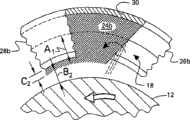
Fig. 1 is the match partial sectional view vertically of multi-stage sealed brush of bank portion of one of vicinity by exemplary embodiments of the present invention;
Fig. 2 is the radially partial sectional view of sealing brush shown in Figure 1 along its 2-2 line;
Fig. 3 is the flow chart according to the method for the multi-stage sealed device shown in exemplary embodiments manufacturing Fig. 1 and 2 of the present invention.
Detailed description of the present invention
Fig. 1 illustrates the sectional view of the multi-stage annular seal arrangement 10 that is provided with coaxially around the circular bank of typical revolution axis type portion 12, and the sealing device is installed in coaxially around the axis of rotating shaft in other words on the annular seal support 14 of vertical center line 16 aptly.
Seal arrangement shown in Figure 1 is used for large scale industry gas turbine engine and steam turbine engines, and the sealing device is a kind of static part stator component in other words of twisted rotary shaft.But, also can be that bank portion 12 is static, and Sealing be mounted to and can rotates with respect to it.
No matter in above-mentioned that a kind of structure, seal arrangement and bank portion all are in relative rotation when engine operation.Seal arrangement is made and can be sealed the pressure reduction that its axially relative both sides keep.For example, fluid (for example steam) 18 is fixed on the right side of seal arrangement, its pressure is P1, and this fluid 18 is sealed effectively by multi-stage sealed device, and reduces between seal arrangement and the bank portion sewing to the left field of the pressure lower (P2) of seal arrangement to greatest extent.
Pressure reduction P1-P2 along the seal arrangement effect when work can be higher, for example, and greater than about 400 pounds/inch
2, and can be significantly higher than 500 pounds/inch
2About (this value is the Maximum differential pressure ability of present known two-stage or multistage conventional seals brush, and its safety coefficient is 2).As mentioned above, common sealing brush can not seal so very high pressure under the situation of the stability of not damaging Sealing or rotor.
The multi-stage sealed device that is shown in Fig. 1 has identical first and second ring packings brush 20,22 of structure, and each sealing brushing tool has a steel wool bundle that is installed in the annular between annular front supporting plate 26a, 26b and annular rear lining plate 28a, the 28b vertically steel tuft 24a, 24b in other words.
The near-end of the above-mentioned first and second steel wool bundle 24a, 24b in other words the bottom by common mode by corresponding weld seam 30 be connected to aptly separately first and second header boards and the back plate corresponding bottom on.
Each sealing brush 20,22 has common ordinary construction, but improves to some extent by the present invention, and is as described below.For example, the end of steel wool bundle extends along the freely section of length A1, A2 from the bottom that it is clipped between the mounting plate, and stretches out with cantilevered fashion outside the end of corresponding back plate 28a, 28b, and forms corresponding radial clearance B1, B2 with contiguous bank portion 12.
In exemplary embodiments shown in Figure 1, the steel wool bundle by annular after the whole radial length of plate 28a, 28b stretch out, and radially extend internally thus.The end of steel wool bundle radially extends internally from the corresponding end of plate afterwards and forms corresponding fence height C1, C2.
Correspondingly, header board 26a, the 26b that matches has from it radially at the radially outside groove of interior end, and this just constitutes axial air gap and form its corresponding free length A1, A2 with the steel wool bundle.In the embodiment shown in fig. 1, two-stage sealing brush separates one section axial spacing D (spacing of measuring) vertically between the steel wool bundle.
Therefore, in the course of the work, have high-pressure liquid 18 at the first header board 26a place of the first sealing brush 20, this fluid 18 is sealed effectively by the first steel wool bundle 24a of the little radial clearance B1 that the permission rotating shaft with correspondence is freely rotated.But, have 18 of some fluids to leak, and flow to the second sealing brush, 22 places downstream by the first steel wool bundle 24a and the first gap B1.Subsequently, this low-pressure fluid is sealed by the second steel wool bundle 24b, and twisted rotary shaft has the second little radial clearance B2 herein.Simultaneously, some low-pressure fluids are sewed to the low pressure area on the surface of the close second back plate 28b by the second steel wool bundle 24b and the second gap B2.
As shown in Figure 2, the second steel wool bundle 24b (and first steel wool bundle 24a shown in Figure 1) tilts between their corresponding mounting plates tangentially, and its tangential tilt angle is about 45-60 °.The sense of rotation that Fig. 2 illustrates rotating shaft bank portion 12 is counterclockwise, the true dip direction of steel wool bundle then in contrast, so between them under once in a while the rubbing action, the steel wool bundle can radially outwardly-bent or warpage.
Single steel wool can be made by any common material (as: alloyed steel), and its diameter is less, several approximately mils, the flexural rigidity the when material composition of steel wool, length, diameter and angle of inclination affect they and rotating shaft 12 frictions.
As mentioned above, it is identical bearing the pressure loading that is caused by pressure reduction P1-P2 that two- stage sealing brush 20,22 is made structure, but conventional structure can not be born and is higher than 550 pounds/inch
2About High Pressure Difference.The steel wool rigidity of this ordinary construction is bigger, and makes rotating shaft increase heating value when rubbing mutually with steel wool, causes rotating shaft to comprise the unstability of swing.
But,, can suitably be improved and significantly improved their common bearing capacity two sealing brushes 20,22, and can not damaged the stability of rotor owing to the friction between the steel wool-bank portion of chance according to the present invention.
Particularly, Fig. 3 illustrates one in a flowchart and makes its structure shown in Fig. 1 and 2 and can improve bearing capacity and have the exemplary embodiments of the multi-stage sealed device 10 of rotor stability.Above-mentioned manufacture method is from the conventional boundary conditions of the environment that form to use multi-stage sealed device engine condition in other words.For example, boundary conditions comprises the stator elements that comprises the rotation closure between steel wool and the bank portion of seal arrangement of total geometric condition that comprises its radial dimension between rotating speed, rotating shaft 12 and the Sealing of temperature, rotating shaft of high pressure and low pressure P1, P2, corresponding pressure reduction, fluid 18 and expectation and the differential heat growth between the rotor element.
The embryonal structure of two sealing brushes 20,22 is that in any conventional manner standard is determined, so that it has maximum load-carrying capacity separately under the high-pressure work load of expection.Therefore, the corresponding original seal structure flexural rigidity that will have a maximum inclination steel wool is born its corresponding pressure maximum load.
Suitable gap B1, the B2 that at first steel wool are designed to have in the exemplary embodiments of seal arrangement shown in Fig. 1 and 2 and rotate between the bank portion 12 normally work rotating shaft 12.Because Sealing is subjected to the differential thermal expansion with respect to rotating shaft,, make corresponding heating value minimum to make it minimum with contacting of rotating shaft 12 so selected at first seal clearance will be reduced or amplify.Be noted that bigger radial clearance can reduce sealability and reduce engine efficiency.
Stipulate two dimension (2-D) calculation process pattern aptly by corresponding software, and analyze in common digital programmable computer 32 (see figure 3)s, with the radial clearance B1 that bears pressure loading, the B2 (preferably both equate) that determines to set in other words two sealing brushes, but do not consider the pressure disturbance problem.In this step of above-mentioned flow process, the structure of multi-stage sealed device is common, does not consider the seal arrangement perturbed problem that original position work meeting takes place in its actual environment.Above-mentioned two dimension (2-D) process mode software is common, for example can be from ABZ company (Virginia, USA, " the design cycle solution " of Chantilly) buying.
By regulating corresponding radial clearance B1, B2, pressure loading is distributed between two sealing brushes equably, but this only is the sealability of analyses and prediction, and does not consider perturbed problem.In fact, the perturbed problem performance that affects multi-stage sealed device significantly is included in the load distribution between the discontinuous sealing brush.
The intensity of multi-stage sealed device only depends on the Sealing that it is the most weak.The destruction of any will cause promptly that another seals brush and destroys during two sealings are brushed, and therefore, the design that common two-stage sealing is brushed has suitable peformance margin, and have above-mentioned corresponding restriction to the pressure load ability.
Usually according to the corresponding fence height C1, the C2 that set the first and second steel wool bundle 24a, 24b by the load of 2-D model prediction and its corresponding thickness E1, E2 (see figure 1), and in multi-stage sealed Design of device, introduce suitable safety coefficient, for example, suitable safety coefficient is about 2.
Disturbance is the important process characteristic of seal arrangement in its predetermined environment, and simply is shown in Fig. 2.When charging fluid 18 passed through between the steel wool of two steel wool bundle 24a, 24b, radially inner elastic bending (shown in dotted line) just took place in steel wool, and this has just reduced the effective clearance between steel wool end and the bank portion 12.The above-mentioned radially inner deflection of steel wool under pressure is little of several mils or several millimeters expressions because of its magnitude, and represents the disturbance effect when working under pressure reduction.
Because above-mentioned disturbing influence the gap between steel wool and the bank portion 12, so it also affects the stability of rotor.Therefore, available common computation fluid dynamics (CFD) is verified the load distribution by the 2-D model prediction, and the sealing stability parameter relevant with rotating shaft work additionally is provided, above-mentioned CFD analysis can be undertaken by three-dimensional (3-D) method in identical or different digital programmable computers 32.Above-mentioned CFD software is common software, for example the STAR-CD of New York, United States Melville CD-adapco company sale.
Employing three-dimensional (3-D) is analyzed, and can further improve the embryonal structures of two sealing brushes, and to satisfy suitable stability criterion, the assurance rotor element is stably worked and for example unallowed swing is not taken place.Preferably adopt the 3-D analytical method to determine free length A1, the A2 of two steel wool bundles and axial spacing D between them and the steel wool flexural rigidity that is produced.
Also can analyze determine best free length, axial spacing and seal clearance B1, B2, so that heating value is minimum and keep suitable stability when taking place to rub between steel wool and the bank portion by 3-D.
The method of the above-mentioned multi-stage sealed device of manufacturing preferably carries out keeping the stability of rotating shaft simultaneously again to determine that its suitable structure is distributed between the two-stage sealing brush with making the load approximate equality in regular turn with analyzing.But, the original position operation of sending out the multi-stage sealed device of this design will take place can not be fully by the performance actual change of analyses and prediction.
Then, by suitable dimensions or scale actual build and test above-mentioned by the multi-stage sealed device of analyzing design, so that determine that by experiment it is in predetermined environment or the performance in the in situ environment.
In the test of multi-stage sealed device, temperature, pressure and mass flow rate between the high and low pressure side of measurement Sealing, to find to measure in other words the disturbance effect of each Sealing, can use above-mentioned identical 2-D process mode to determine the above-mentioned disturbance effect of each Sealing according to measured performance data according to a conventional method.
Then, adopt the 2-D process mode to reset radial clearance B1, the B2 of each Sealing again, so that pressure loading approximate equality ground under the effect of the disturbance of being measured distributes.Can adopt engineering evaluation or test and reduction value increase or reduce two gap B1, B2 that combine with the disturbed value of its corresponding measurement analog value so that pressure loading distribute equably.
Like this, can under the situation of not considering disturbance effect, design multi-stage sealed device at first according to a conventional method by analyzing, then the stability of its original position operation is carried out optimization, build its sealability of this device and experiment test and characteristic then, the data that get with experiment are determined the disturbed value under pressure reduction then, again the design of seal arrangement is done further to improve, when counting the disturbed value of measuring, load being distributed equably, and reach stable work.
The method of the above-mentioned multi-stage sealed device of manufacturing causes two sealing brushes identical aspect other of structure and shape, but but they will approximate equality ground original position share pressure loading when keeping rotor stability on request.Like this, just can design impartial more accurately two sealing brushes sharing pressure loading, this has just correspondingly improved them and has shared safely along the integration capability of the total pressure reduction of multi-stage sealed device effect.The geometric condition of two sealing brushes less but very important variation can improve its pressure reduction ability significantly, this point can predetermined without undergoing the environment of agitation in in-situ accomplishes reliably.
In addition, above-mentioned method also can be further used for designing sealing brush 3 grades or multistage, and accurately controls the load distribution that comprises the disturbance effect on each Sealing between them.As mentioned above, the common multi-stage sealed brush that surpasses two-stage few (if any) improves the third level or more multistage bearing capacity.
By predicting or further test the characteristic of multi-stage sealed device and can further improving above-mentioned multi-stage sealed device in the performance of the medium-term and long-term work of specific environment.Sealing in long-term work, can owing to wearing and tearing and other factors that influence performance its performance is changed.Estimate sealability at the appointed time and can determine the variation of the agitation of the variation of engine condition or each utmost point Sealing, be used for further improving seal configuration to keep the superperformance that has in its long-term work.
Special advantage of the present invention is, two sealing brushes 20,22 have roughly the same common in other words structure, but its single structure feature has the not isostructure of sharing the pressure loading (preferably sharing load equably) that has agitation.Method shown in Figure 3 begins with the definition that each has the sealing brush of roughly the same DESIGNED FEATURE and structure (comprising size and dimension) and material property.Each sealing brushing tool has the steel wool bundle that is installed between the corresponding forward and backward plate, and is mounted to and has various physical dimension A, B, C and E, and two sealing brushes separate a space D vertically.
Reconstruct the sealing brush by the aforesaid embryonal structure that changes the sealing brush, to apply total pressure loading of (changing very little) with following the prescribed order with sharing approximate equality.And above-mentioned load distribution is to realize in situ in predetermined environment the meeting that is applied causes the effect of pressure loading of corresponding disturbance effect in each Sealing under.
Two of above-mentioned sealing brush had not only influenced sealability but also had influenced and the structure characteristic of the stability during the rotating shaft friction is gap B1, B2 between steel wool and the rotating shaft 12 and the filling density of steel wool bundle, and this assembling sealing is represented with the steel wool number that each seals on the periphery of brushing on along the circumferential direction the unit length.
The structure and the shape of two sealing brushes can be roughly the same, but, single structure feature in the preferred embodiment has as stated above determine multi-form for different sealing brushing tools, so as to make two sealing brushes under the effect of disturbance advantageously equalization share pressure loading.
In an embodiment by the sealing brush that is shown in Fig. 1 and 2 of method manufacturing shown in Figure 3, the structure of sealing brush can be identical, but gap B1, B2 between the terminal and contiguous bank of the steel wool separately portion 12 are different.In the embryonal structure of sealing brush, above-mentioned each gap equates, but afterwards according to above-mentioned method change, so that under disturbed conditions, share load between them equably, and with rotating shaft 12 frictions the time, stably work.
The occurrence in various gaps will be according to the boundary conditions and the Sealing of work and the basic geometric condition of the bank portion that matches through once once more design change.But, because two-stage conventional seals brush is not to share total load equably usually, the brush of the sealing in downstream is just shared bigger load than the sealing brush of upstream, so the gap B2 of the second sealing brush 22 in downstream shown in Figure 1 is more preferably greater than the gap B1 of the first sealing brush 20 of upstream, so that reach in the desirable impartial load distribution of estimating to bear under the agitation of high pressure load very.Correspondingly, can also to be that other aspects are identical comprise that the filling density of its steel wool is identical to the structure of two sealing brushes.
In another embodiment shown in Figure 3, two sealing brushes filling density separately can have single people or common structure characteristic, and this feature differences in two sealing brushes are so that be implemented in impartial load distribution and rotating shaft working stability under the disturbed conditions.In the present embodiment, two sealing brush gap B1, B2 separately can be equal to each other and for example be zero, and this has just formed interference or contact matching between steel wool end and the rotating shaft.Though steel wool and rotating shaft 12 contact with each other and friction mutually when work, steel wool is still standing to increase the agitation of the frictional force of countershaft 12, and owing to the rotating shaft frictional heating influences its working stability.
However, method shown in Figure 3 still can be applicable to different structure characteristics for example gap or filling density and determine its required value, so that distribute the pressure loading that has agitation between two sealing brushes.Because the filling density value has influence on sewing of the fluid that flows through between the steel wool, so this value should be adjusted by above-mentioned method as the steel wool tip gap and be made it optimization in other words, to regulate the load capacity of carrying separately, reach predetermined impartial distribution of the load under agitation by two sealing brushes.
Another advantage of method shown in Figure 3 is, multi-stage sealed device 10 shown in Figure 1 can have the sealing brush of two or more parallel arranged, and this seal arrangement 10 can have or not have for example labyrinth shown in this paper Fig. 1 34 of additional Sealing.This labyrinth is made of a series of axially spaced annular tooth, between annular tooth tip and the rotating shaft 12 corresponding gap is arranged.
Above-mentioned labyrinth 34 practical experience design and creating to share a part of load in total pressure loading routinely itself, remaining pressure loading then is distributed between two sealing brushes 20,22 making by method shown in Figure 3 equably.But be distributed in to a part of load approximate equality in total pressure loading between first and second sealing brush 20,22, the load that they should bear mutually is because architectural difference and different with the pressure loading of labyrinth 34.Because the sealability of sealing brush is strong, so two sealing brushes shown in Figure 1 will be shared jointly by the most load in total pressure loading of whole multi-stage sealed device.
In design method shown in Figure 3, introduce influence, just can design the sealing brush that is used for specific environment more accurately by the agitation and the rotor stability of test determination.Therefore, when original position is inserted the sealing brush in specific environment and under the predetermined pressure loading condition, its load distribution can be that approximate equality is uniform in other words, and makes each sealing brushing tool that maximum bearing capacity be arranged, thereby guarantees the efficient and the working life of its assembly.
Like this, the sealing of any routine brush especially be the sealing brush of very high pressure design, all can be improved as stated above and use side by side under the load of balancedly distributing between them.Above-mentioned design method can guarantee can not to take place a sealing brush overload and the situation of another sealing brush load deficiency, therefore, and bigger total pressure loading that the sealing configuration of combination can the previous device of share ratio may be shared.In addition, can design the total bearing capacity that further improves multi-stage sealed device more than the sealing brush of two-stage by above-mentioned method, with total pressure loading ability of further raising seal arrangement, this is former to be impossible.
Though the content that is considered to preferred and typical embodiment of the present invention has been described in the above, but, persons skilled in the art will understand other remodeling of the present invention from principle as herein described, therefore, all remodeling that all be fallen in practicalness of the present invention and the scope are all included in the appended claims.
Claims (8)
1. method of making multi-stage sealed device comprises following steps:
Regulation has the original first and second sealing brushes of common structure at first, is used for the pressure reduction of common sealing along the bank portion that rotates with respect to the above-mentioned first and second sealing brushes;
Improvement is shared and is caused by above-mentioned pressure reduction but do not consider the common structure characteristic of the above-mentioned first and second sealing brushes of the load of pressure disturbance, common structure feature of this first sealing brush structurally is changed being different from the common structure feature of this second sealing brush, thus the impartial load of sharing under described pressure disturbance;
Improve the stability of the above-mentioned first and second sealing brushes to guarantee to rotate with respect to above-mentioned bank portion;
Determine the pressure disturbance of the described first and second sealing brushes under test pressure; And
The information that utilization obtains from the pressure disturbance of determining the described first and second sealing brushes under test pressure is further improved the improved described common structure feature of the described first and second sealing brushes, so that share pressure loading equably under described pressure disturbance.
2. by the method for claim 1, it is characterized in that,
The above-mentioned first and second sealing brushing tools of original regulation have above-mentioned common structure, comprise the steel wool bundle that is installed in vertically between header board and the back plate, and the end of above-mentioned steel wool bundle extends along the free length direction; With
The free length of above-mentioned steel wool bundle and rigidity are improved so that to produce heat when they and the friction of above-mentioned bank portion minimum, with the stability that guarantees to rotate with respect to above-mentioned bank portion.
3. by the method for claim 2, it is characterized in that,
The step of determining pressure disturbance comprises that sealing brush to above-mentioned first and second tests to measure pressure, temperature and the mass flow rate by the fluid of above-mentioned pressure differential; With
The above-mentioned pressure of measuring, temperature and mass flow rate are analyzed to determine the above-mentioned disturbance of each above-mentioned first and second sealing brush.
4. by the method for claim 3, it is characterized in that,
End and the gap between the bank portion at described steel wool bundle are different at the described first and second sealing brush places, to share described pressure loading.
5. by the method for claim 3, it is characterized in that,
The packing density of described steel wool bundle is different for the described first and second sealing brushes, to share described pressure loading.
6. a multi-stage sealed device of making by the method for claim 1 is characterized in that,
Have the above-mentioned first and second sealing brushes of different configurations, share at the above-mentioned pressure loading that has under the pressure disturbance situation in order to approximate equality ground.
7. a seal arrangement made from the method for claim 2 is characterized in that,
The common structure characteristic of the described first and second sealing brushes be the gap between the terminal and described bank portion of described steel wool bundle, and to seal the brush places described first and second be different in described gap, to share described pressure loading.
8. a seal arrangement made from the method for claim 2 is characterized in that,
The common structure characteristic of the described first and second sealing brushes is the filling density of described steel wool bundle, and described filling density is different for the first and second sealing brushes, to share described pressure.
Applications Claiming Priority (2)
| Application Number | Priority Date | Filing Date | Title |
|---|---|---|---|
| US10/227,643 US6854735B2 (en) | 2002-08-26 | 2002-08-26 | In situ load sharing brush seals |
| US10/227643 | 2002-08-26 |
Publications (2)
| Publication Number | Publication Date |
|---|---|
| CN1495340A CN1495340A (en) | 2004-05-12 |
| CN100538020C true CN100538020C (en) | 2009-09-09 |
Family
ID=31887506
Family Applications (1)
| Application Number | Title | Priority Date | Filing Date |
|---|---|---|---|
| CNB031549802A Expired - Fee Related CN100538020C (en) | 2002-08-26 | 2003-08-26 | Original position load sharing sealing brush |
Country Status (5)
| Country | Link |
|---|---|
| US (1) | US6854735B2 (en) |
| JP (1) | JP4618991B2 (en) |
| KR (1) | KR100912997B1 (en) |
| CN (1) | CN100538020C (en) |
| RU (1) | RU2331808C2 (en) |
Families Citing this family (23)
| Publication number | Priority date | Publication date | Assignee | Title |
|---|---|---|---|---|
| US7040861B2 (en) * | 2004-03-04 | 2006-05-09 | General Electric Company | Method and apparatus for reducing self sealing flow in combined-cycle steam turbines |
| JP4776249B2 (en) * | 2005-02-25 | 2011-09-21 | 株式会社東芝 | Liquid shaft seal device and rotating electric machine using the shaft seal device |
| US8167313B2 (en) * | 2005-11-21 | 2012-05-01 | General Electric Company | Seal member, assembly and method |
| EP1813840A1 (en) * | 2006-01-26 | 2007-08-01 | Siemens Aktiengesellschaft | Multi-stage brush seal |
| US7703774B2 (en) * | 2006-09-12 | 2010-04-27 | General Electric Company | Shaft seal using shingle members |
| US20080107525A1 (en) * | 2006-11-02 | 2008-05-08 | General Electric Company | Shaft seal formed of tapered compliant plate members |
| US20080217859A1 (en) * | 2007-03-05 | 2008-09-11 | United Technologies Corporation | Speed fit brush seal |
| DE102007018063B4 (en) | 2007-04-17 | 2012-02-09 | Siemens Ag | Impulse turbine |
| US8080973B2 (en) | 2008-10-22 | 2011-12-20 | General Electric Company | Apparatus for energy transfer using converter and method of manufacturing same |
| US7932633B2 (en) | 2008-10-22 | 2011-04-26 | General Electric Company | Apparatus for transferring energy using power electronics and machine inductance and method of manufacturing same |
| DE102008055736A1 (en) * | 2008-11-04 | 2010-05-12 | Siemens Aktiengesellschaft | Brush seal for a turbomachine and turbo machine with a brush ring seal assembly |
| US20100164177A1 (en) * | 2008-12-30 | 2010-07-01 | Eaton Corporation | Hybrid multistage brush seal |
| US8061984B2 (en) * | 2009-04-06 | 2011-11-22 | Dresser-Rand Company | Dry gas blow down seal |
| US8206082B2 (en) * | 2009-04-29 | 2012-06-26 | General Electric Company | Packing seal rotor lands |
| US8505923B2 (en) * | 2009-08-31 | 2013-08-13 | Sealeze, A Unit of Jason, Inc. | Brush seal with stress and deflection accommodating membrane |
| US8936247B2 (en) | 2010-05-18 | 2015-01-20 | General Electric Company | Seal assembly including plateau and concave portion in mating surface for seal tooth in turbine |
| US9290097B2 (en) | 2010-11-05 | 2016-03-22 | Robert Louis Steigerwald | Apparatus for transferring energy using onboard power electronics with high-frequency transformer isolation and method of manufacturing same |
| DE102011080834A1 (en) * | 2011-08-11 | 2013-02-14 | Siemens Aktiengesellschaft | brush seal |
| US8932001B2 (en) * | 2011-09-06 | 2015-01-13 | General Electric Company | Systems, methods, and apparatus for a labyrinth seal |
| US20130181408A1 (en) * | 2012-01-13 | 2013-07-18 | General Electric Company | Brush seal arrangement combined with honeycomb seal |
| FR2998922B1 (en) * | 2012-12-05 | 2018-06-15 | Safran Aircraft Engines | SEALING OF TURBOMACHINE SPEAKERS REALIZED BY BRUSH JOINT AND LABYRINTH |
| US9995164B2 (en) * | 2012-12-13 | 2018-06-12 | Mitsubishi Hitachi Power Systems, Ltd. | Rotating fluid machine |
| KR101524627B1 (en) * | 2015-03-05 | 2015-06-16 | 터보파워텍(주) | hybrid sealing apparatus of turbine |
Citations (1)
| Publication number | Priority date | Publication date | Assignee | Title |
|---|---|---|---|---|
| US6131910A (en) * | 1992-11-19 | 2000-10-17 | General Electric Co. | Brush seals and combined labyrinth and brush seals for rotary machines |
Family Cites Families (18)
| Publication number | Priority date | Publication date | Assignee | Title |
|---|---|---|---|---|
| GB2198195B (en) * | 1986-12-06 | 1990-05-16 | Rolls Royce Plc | Brush seal |
| US5106104A (en) * | 1990-10-11 | 1992-04-21 | General Electric Company | Constant pressure drop multiple stage brush seal |
| GB9103459D0 (en) * | 1991-02-19 | 1991-04-03 | Cross Mfg Co | Brush seal assembly |
| US5758879A (en) * | 1991-08-01 | 1998-06-02 | Cross Manufacturing Company (1938) Limited | Brush seal assembly |
| US5181728A (en) * | 1991-09-23 | 1993-01-26 | General Electric Company | Trenched brush seal |
| US5335920A (en) * | 1992-08-20 | 1994-08-09 | General Electric Company | Brush seal |
| US5568931A (en) * | 1992-08-20 | 1996-10-29 | General Electric Company | Brush seal |
| US5794942A (en) * | 1993-01-08 | 1998-08-18 | The Texas A&M University System | Modulated pressure damper seals |
| US5630590A (en) * | 1996-03-26 | 1997-05-20 | United Technologies Corporation | Method and apparatus for improving the airsealing effectiveness in a turbine engine |
| US5961279A (en) * | 1996-05-31 | 1999-10-05 | Atlantic Richfield Company | Turbine power plant having minimal-contact brush seal augmented labyrinth seal |
| CA2205877A1 (en) * | 1996-06-28 | 1997-12-28 | General Electric Company | Brush seals and combined labyrinth and brush seals for rotary machines |
| US6283716B1 (en) * | 1997-10-28 | 2001-09-04 | Coltec Industries Inc. | Multistage blowdown valve for a compressor system |
| WO1999030065A1 (en) * | 1997-12-11 | 1999-06-17 | Watson Cogeneration Company | Turbine power plant having minimal-contact brush seal augmented labyrinth seal |
| GB9821927D0 (en) * | 1998-10-08 | 1998-12-02 | Rolls Royce Plc | Improved brush seal |
| US6435011B1 (en) * | 1999-02-18 | 2002-08-20 | General Electric Company | Method and apparatus for determining if brush seals are defective |
| WO2001055624A1 (en) * | 2000-01-31 | 2001-08-02 | General Electric Company | Brush seals for steam turbine applications |
| PT1783406E (en) * | 2000-04-06 | 2010-10-21 | Turbocare Inc | Improved brush-seal designs for turbines and similar rotary apparatus |
| US6378371B1 (en) * | 2000-09-29 | 2002-04-30 | General Electric Company | Apparatus and methods for determining natural frequencies of brush seals |
-
2002
- 2002-08-26 US US10/227,643 patent/US6854735B2/en not_active Expired - Fee Related
-
2003
- 2003-08-25 KR KR1020030058612A patent/KR100912997B1/en not_active IP Right Cessation
- 2003-08-25 RU RU2003125960/06A patent/RU2331808C2/en not_active IP Right Cessation
- 2003-08-26 JP JP2003301000A patent/JP4618991B2/en not_active Expired - Fee Related
- 2003-08-26 CN CNB031549802A patent/CN100538020C/en not_active Expired - Fee Related
Patent Citations (1)
| Publication number | Priority date | Publication date | Assignee | Title |
|---|---|---|---|---|
| US6131910A (en) * | 1992-11-19 | 2000-10-17 | General Electric Co. | Brush seals and combined labyrinth and brush seals for rotary machines |
Also Published As
| Publication number | Publication date |
|---|---|
| JP2004084951A (en) | 2004-03-18 |
| KR20040018950A (en) | 2004-03-04 |
| JP4618991B2 (en) | 2011-01-26 |
| RU2331808C2 (en) | 2008-08-20 |
| US20040036227A1 (en) | 2004-02-26 |
| CN1495340A (en) | 2004-05-12 |
| US6854735B2 (en) | 2005-02-15 |
| KR100912997B1 (en) | 2009-08-20 |
| RU2003125960A (en) | 2005-02-20 |
Similar Documents
| Publication | Publication Date | Title |
|---|---|---|
| CN100538020C (en) | Original position load sharing sealing brush | |
| Yoon et al. | Effect of the stator hub configuration and stage design parameters on aerodynamic loss in axial compressors | |
| McGreehan et al. | Power dissipation in smooth and honeycomb labyrinth seals | |
| Yoon et al. | The effect of clearance on shrouded and unshrouded turbines at two levels of reaction | |
| Chew et al. | Simulation of flow and heat transfer in the tip region of a brush seal | |
| Sorokes et al. | Investigation of the circumferential static pressure non-uniformity caused by a centrifugal compressor discharge volute | |
| Rhode et al. | Three-dimensional computations of rotordynamic force distributions in a labyrinth seal | |
| Raben et al. | Brush seals used in steam environments—chronological wear development and the impact of different seal designs | |
| Li et al. | Experimental investigation on leakage characteristics of low-hysteresis brush seals | |
| Das et al. | A review on diagnostic techniques of bearing fault and its modeling in induction motor | |
| Gong et al. | A computational model for short wavelength stall inception and development in multi-stage compressors | |
| Li et al. | A comparison of static and rotordynamic characteristics for two types of liquid annular seals with parallelly grooved stator/rotor | |
| Stephen et al. | Development of brush seal technology for steam turbine retrofit applications | |
| Cangioli et al. | Rotordynamic characterization of a staggered labyrinth seal: experimental test data and comparison with predictions | |
| Rhode et al. | Computed effect of rub-groove size on stepped labyrinth seal performance | |
| Li et al. | The effects of clearance sizes on labyrinth brush seal leakage performance using a Reynolds-averaged Navier—Stokes solver and non-Darcian porous medium model | |
| Long et al. | Contact force measurements under a brush seal | |
| Husak et al. | Numerical analysis of screw compressor rotor and casing deformations | |
| Zhao et al. | Role of distributed interbristle friction force on brush seal hysteresis | |
| Thakur et al. | Prediction of Flow in Centrifugal Blower Using Quasi-Steady Rotor–Stator Models | |
| Li et al. | Effects of clearances on the leakage flow characteristics of two kinds of brush seals and referenced labyrinth seal | |
| Goel | Availability and profit analysis of gas turbine system using new type of generalized trapezoidal fuzzy numbers | |
| Lelli et al. | Combined 3D fluid dynamics and mechanical modelling of brush seals | |
| Dinc et al. | Fundamental design issues of brush seals for industrial applications | |
| Zhang et al. | Experimental and Numerical Investigations on the Leakage Flow Characteristics of Helical-Labyrinth-Brush Seals |
Legal Events
| Date | Code | Title | Description |
|---|---|---|---|
| C06 | Publication | ||
| PB01 | Publication | ||
| C10 | Entry into substantive examination | ||
| SE01 | Entry into force of request for substantive examination | ||
| C14 | Grant of patent or utility model | ||
| GR01 | Patent grant | ||
| C17 | Cessation of patent right | ||
| CF01 | Termination of patent right due to non-payment of annual fee |
Granted publication date: 20090909 Termination date: 20130826 |