CN100536772C - Method and apparatus for object collision detection utilizing a PID controller in a motorized, mobile C-arm - Google Patents
Method and apparatus for object collision detection utilizing a PID controller in a motorized, mobile C-arm Download PDFInfo
- Publication number
- CN100536772C CN100536772C CNB2004100447609A CN200410044760A CN100536772C CN 100536772 C CN100536772 C CN 100536772C CN B2004100447609 A CNB2004100447609 A CN B2004100447609A CN 200410044760 A CN200410044760 A CN 200410044760A CN 100536772 C CN100536772 C CN 100536772C
- Authority
- CN
- China
- Prior art keywords
- arm
- error
- position error
- limit
- controller
- Prior art date
- Legal status (The legal status is an assumption and is not a legal conclusion. Google has not performed a legal analysis and makes no representation as to the accuracy of the status listed.)
- Expired - Fee Related
Links
- 238000001514 detection method Methods 0.000 title claims abstract description 16
- 238000000034 method Methods 0.000 title claims description 17
- 230000033001 locomotion Effects 0.000 claims abstract description 39
- 238000007620 mathematical function Methods 0.000 claims description 6
- 238000004364 calculation method Methods 0.000 claims description 2
- 230000001105 regulatory effect Effects 0.000 claims 2
- 238000003384 imaging method Methods 0.000 description 25
- 238000010276 construction Methods 0.000 description 9
- 230000011664 signaling Effects 0.000 description 5
- 230000006378 damage Effects 0.000 description 3
- 238000003745 diagnosis Methods 0.000 description 2
- 238000005259 measurement Methods 0.000 description 2
- 238000012986 modification Methods 0.000 description 2
- 230000004048 modification Effects 0.000 description 2
- 230000009897 systematic effect Effects 0.000 description 2
- 238000003325 tomography Methods 0.000 description 2
- 230000036592 analgesia Effects 0.000 description 1
- 230000000747 cardiac effect Effects 0.000 description 1
- 230000002950 deficient Effects 0.000 description 1
- 238000002059 diagnostic imaging Methods 0.000 description 1
- 238000010894 electron beam technology Methods 0.000 description 1
- 238000005516 engineering process Methods 0.000 description 1
- 239000012530 fluid Substances 0.000 description 1
- 238000002682 general surgery Methods 0.000 description 1
- 238000012423 maintenance Methods 0.000 description 1
- 238000004519 manufacturing process Methods 0.000 description 1
- 239000000463 material Substances 0.000 description 1
- 230000003287 optical effect Effects 0.000 description 1
- 230000000399 orthopedic effect Effects 0.000 description 1
- 230000001915 proofreading effect Effects 0.000 description 1
- 238000002601 radiography Methods 0.000 description 1
- 239000000725 suspension Substances 0.000 description 1
- 238000002560 therapeutic procedure Methods 0.000 description 1
- 230000002792 vascular Effects 0.000 description 1
Images


Classifications
-
- A—HUMAN NECESSITIES
- A61—MEDICAL OR VETERINARY SCIENCE; HYGIENE
- A61B—DIAGNOSIS; SURGERY; IDENTIFICATION
- A61B6/00—Apparatus for radiation diagnosis, e.g. combined with radiation therapy equipment
- A61B6/44—Constructional features of apparatus for radiation diagnosis
- A61B6/4429—Constructional features of apparatus for radiation diagnosis related to the mounting of source units and detector units
- A61B6/4435—Constructional features of apparatus for radiation diagnosis related to the mounting of source units and detector units the source unit and the detector unit being coupled by a rigid structure
- A61B6/4441—Constructional features of apparatus for radiation diagnosis related to the mounting of source units and detector units the source unit and the detector unit being coupled by a rigid structure the rigid structure being a C-arm or U-arm
-
- A—HUMAN NECESSITIES
- A61—MEDICAL OR VETERINARY SCIENCE; HYGIENE
- A61B—DIAGNOSIS; SURGERY; IDENTIFICATION
- A61B6/00—Apparatus for radiation diagnosis, e.g. combined with radiation therapy equipment
- A61B6/10—Application or adaptation of safety means
- A61B6/102—Protection against mechanical damage, e.g. anti-collision devices
-
- A—HUMAN NECESSITIES
- A61—MEDICAL OR VETERINARY SCIENCE; HYGIENE
- A61B—DIAGNOSIS; SURGERY; IDENTIFICATION
- A61B6/00—Apparatus for radiation diagnosis, e.g. combined with radiation therapy equipment
- A61B6/44—Constructional features of apparatus for radiation diagnosis
- A61B6/4405—Constructional features of apparatus for radiation diagnosis the apparatus being movable or portable, e.g. handheld or mounted on a trolley
Abstract
Certain embodiments of the present invention relate to a collision detection system. The collision detection system includes a position indicator for determining an actual position of a component connected to the collision detection system. The system also includes an error calculator for determining a position error between the actual position and a selected position. The system further includes a comparator for comparing the position error to a position error limit. The comparator generates a halt signal based on the position error and position error limit. The system also includes a motion controller for controlling motion of the component. The motion controller stops motion of the component based on the halt signal. The comparator generates a halt signal when the position error is equal to or greater than the position error limit.
Description
Technical field
The present invention relates in general detect in the movable part of imaging system and the collision between the target.Specifically, the present invention relates to that usage ratio integral differential (PID) controller carries out the target collision detection on vehicularized mobile C-arm.
Background technology
The medical diagnosis imaging system comprises various imaging patterns, such as X-ray system, computerized tomography (CT) system, ultrasonic system, electron beam tomography (EBT) system, magnetic resonance (MR) system etc.The medical diagnosis imaging system is for example by being exposed to energy source such as the image that produces target (such as the patient) in the X-ray by the patient.The image that is produced can be used for many purposes.For example, can detect defective in target internal.In addition, can determine internal structure or aligned variation.Also can be illustrated in the fluid flow in the target.In addition, this image may be displayed on the existence of target internal object or does not exist.The information of being obtained from medical diagnostic imaging system has application in a lot of fields, comprises medical science and manufacturing field.
The radiant image device accurately is provided with near wanting the patient of imaging or target so that the image-forming information of expection is provided such as the X-radiography unit usually.One type radiant image device is mobile C-arm system.In medical field, mobile C-arm system for example can be used for general surgery, orthopedic treatment, analgesia therapy, vascular treatment and cardiac treatment.Usually, mobile C-arm has the X-ray source on the end that is installed to main frame and is installed in detector (such as image intensifier) on the other end of main frame.Mobile C-arm can move with respect to the target of wanting imaging (such as the patient).
Any axial mechanization campaign of mobile C-arm system brings danger all may for patient and imaging system and other equipment.It is desirable to stop the collision between mobile C-arm and target (such as the patient) or it is minimized.It is follow the tracks of to move or by importing mobile from the user interface facilities end user by automatic orbit that possibility of collision is present in the C-arm.Therefore, it is desirable to prevent collision during by external user and automatic system or programme-control or collision is minimized at mobile C-arm.It also is in demand making the minimized method and system of collision of generation.
Imaging system is usually used a kind of in two types the anticollision pick off: touch sensor and proximity transducer.Proximity transducer detects target and is present in the given distance of the moving-member of C-arm imaging device.Proximity transducer can be an electrical capacitance proximity sensor.Current proximity transducer is subjected to the restriction of the complexity of electronic circuit.Complicated additional influence circuit for example cost of imaging system, maintenance and performance.Current sensing system also is subjected to the restriction of the distance between pick off and imaging system components.That is, the operational constraints condition restriction for example at proximity transducer with become distance between the image intensifier.In addition, mobile C-arm equipment does not also use electric capacity near sensing.
The crash sensor of another kind of type is a touch sensor.Touch sensor can use for example buffer.Touch sensor detects the variation of the signal that is produced when buffer touches target.Usually, touch sensor detects the variation of the pressure that causes with contacting of target.
Yet mistake will be collided as the error in systematic function by current system.This misunderstanding may cause bigger power is applied to motor in vehicularized C-arm system.At last, this system may be applied to system with the moment of torsion of maximum thus with available peak power.The bigger power that higher moment of torsion may cause being difficult to bear is applied on the target of being collided.
Therefore, need a kind of improved method and system that on vehicularized mobile C-arm system, carries out the target collision detection.
Summary of the invention
Some embodiment of the present invention provides the method and system of the improved collision detection of the vehicularized C-arm imaging system that is used for moving.In a certain embodiment, this system comprises removable C-arm, the position indicator of determining the physical location of C-arm of settling X-ray source and X-ray receiver, determine the motion controller of the motion of the comparator of Error Calculator, comparison position sum of errors position error limit in the physical location of C-arm and the site error between the selected position and control C-arm.Comparator position-based sum of errors position error limit output stop signal.Motion controller stops the motion of C-arm based on stop signal.
In one embodiment, output stop signal when site error is equal to or greater than position error limit.Replacedly, output stop signal when site error is equal to or greater than position error limit above predetermined amount of time.In one embodiment, Error Calculator is determined site error by deduct actual position from selected position.In one embodiment, use at least a definite selected position in user interface and the automatic control.
Position indicator for example can be an encoder.Motion controller can be PID (PID) controller.Position error limit for example can be signal value, value table and/or mathematical function.
This system also can comprise the motor that drives the C-arm.Motor receives the control signal from motion controller.This system also comprises main control unit.Main control unit sends instruction to motion controller.Main control unit receives stop signal and sends halt instruction to motion controller from comparator.
Some embodiment of method comprises current location and the site error of calculating between current location and desired location of determining the C-arm.This method also comprises comparison position sum of errors position error limit and produces control signal to stop the C-arm when site error is equal to or greater than position error limit.In one embodiment, site error can be calculated by deduct physical location from the position of expection.In addition, position error limit can be determined by using signal value, value table and/or mathematical function.The position of expection can use user interface and/or control is definite automatically.
Description of drawings
Accompanying drawing 1 is depicted as the mobile C-arm imaging system according to some embodiment of the present invention.
Accompanying drawing 2 is depicted as vehicularized C-arm system controller according to an embodiment of the present.
Accompanying drawing 3 is depicted as another embodiment of C-arm system controller according to an embodiment of the present.
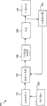
Accompanying drawing 4 is depicted as the C-arm system controller that uses in according to an embodiment of the present.
The in check C-arm position that accompanying drawing 5 is depicted as according to an embodiment of the present C-arm system arbitrarily is the curve chart of actual C-arm position relatively.
Accompanying drawing 6 is depicted as according to an embodiment of the present position error signal the relative position error limiting figure of C-arm system arbitrarily.
Accompanying drawing 7 is depicted as the position error signal of comparing with position error limit according to an embodiment of the present.
Accompanying drawing 8 is depicted as the method for the collision detection in the mobile C-arm system that uses in according to an embodiment of the present.
The specific embodiment
Reading in conjunction with the accompanying drawings will be better understood the detailed description of the general introduction of preamble and some embodiment of the present invention hereinafter.For the present invention being described, some embodiment shown in the drawings.It should be understood, however, that structure and the means of the present invention shown in being not limited in the accompanying drawings.
The detailed description of invention
Just to illustrative purposes, detailed description hereinafter is with reference to a certain embodiment of the X-radiation imaging system that uses the vehicularized C-arm that moves.It should be understood that the present invention also can use other imaging system.
Accompanying drawing 1 is depicted as the mobile C-arm imaging system of using 100 in some embodiment according to the present invention.System 100 comprises C-arm 110, picture receiver 120, X-ray source 130, supporting construction 140 and the base 150 of wheel is arranged.Picture receiver 120 is installed on the relative position of C-arm 110 with X-ray source 130.Supporting construction 140 provides the support of C-arm 110 and C-arm 110 is remained in the position of suspension.Supporting construction 140 is installed in permission system 100 movably to be had on the base 150 of wheel.The example of mobile C-arm imaging system is described in U.S. Pat 5,583 in further detail, in 909, this in the mode of incorporated by reference with it in conjunction with in this application.
Supporting construction 140 provides stable balanced support for C-arm 110.Supporting construction 140 is hanged and is being held C-arm 110 so that for example patient or target are being carried out using in the imaging.Supporting construction 140 also allows C-arm 110 to rotate (for example manual or use motor) around rotating shaft.Supporting construction 140 be connected to wheel is for example arranged base 150 so that mobile C-arm imaging system 100 is relocated.
The target that C-arm 110 allows picture receivers 120 and X-ray source 130 to install and be positioned to want imaging is such as around the patient.C-arm 110 for example can be circular C-shape or arc part.C-arm 110 can make picture receiver 120 and X-ray source 130 locate selectively with respect to the patient in the internal freedom space that is positioned at C-arm 110 or the width and the length of other target.
Picture receiver 120 for example can be image intensifier or other the energy receiver used in diagnosing image.Picture receiver 120 and X-ray source 130 are installed on the relative position of C-arm 110.Use C-arm 110 and supporting construction 140, picture receiver 120 and X-ray source 130 can be positioned at target such as around the patient.Picture receiver 120 and X-ray source 130 are used to produce the diagnostic image of the target that is expressed as picture.
In operation, for example the patient places and is positioned on the picture receiver 120 and the tables between the X-ray source 130 that is installed on the C-arm 110.Supporting construction 140 moves C-arm 110.By mobile C-arm 100 picture receiver 120 and X-ray source 130 are positioned on the position of expecting with respect to the patient.Picture receiver 120 can be positioned near the to improve resulting picture quality of patient.
Some embodiment of the present invention provides touch sensor, and this pick off for example is used for mobile C-arm imaging system, such as in 1 described C-arm imaging system with reference to the accompanying drawings above.Mobile picture receiver 120 has increased in other parts of picture receiver 120 or C-arm 110 and the danger of the collision between patient, tables or other the target to improve graphical quality near patient or other target.Some embodiment detects the collision between system 100 and patient who is just checking or other target.Carry out collision detection to prevent because the influence of C-arm system 100 and overcompensation and in system 100, produce further error.
Accompanying drawing 2 is depicted as vehicularized C-arm system controller 200 according to an embodiment of the present.Controller 200 comprises main control unit 210, closed loop controller 220 and user interface 230.Controller 200 is connected to the C-arm system such as C-arm system 100.Closed loop controller 220 can comprise PID (PID) motor control ring or other control loop.
In operation, the user is by user interface 230 input instructions.User instruction is sent to main control unit 210.Main control unit 210 sends to closed loop controller 220 with position command.Closed loop controller 220 sends control signal to C-arm system 100 then.
Accompanying drawing 3 is depicted as another embodiment of the C-arm system controller 300 that uses in according to an embodiment of the present.System controller 300 comprises main control unit 310, PID motion controller 320, user interface 330, motor 340, position indicator 350 and is connected to the Error Calculator 360 of C-arm system 100.Some embodiment utilizes the site error value that mobile imaging system (such as mobile C-arm system) is carried out collision detection.The absolute value of successive site error value can compare with preset value in the process of the motion of parts (such as C-arm 110).If the site error value surpasses preset value then moves and can be stopped or slow down.The class of operation of controller 300 is similar to the operation of controller 400 described below.
In the system of routine, PID motion controller 320 is interpreted as collision the performance error of system 100.As a result, the PID motion controller applies bigger power to attempt correcting feature for motor 340.Yet the function of increase motor 340 has just increased the moment of torsion to system 100.The moment of torsion that increases has caused applying power to the target that the parts (such as C-arm 110) with system 100 collide.
Accompanying drawing 4 is depicted as the C-arm system controller 400 that uses in according to an embodiment of the present.System controller 400 is similar to the 3 C-arm system controllers of describing 300 with reference to the accompanying drawings.System controller 400 comprises main control unit 410, PID motion controller 420, user interface 430, motor 440, position indicator 450, Error Calculator 460, error comparator 470, position error limit 480 and stop signal 490.
C-arm system controller 400 (and above-described controller 200 and 300) also can be used for other system and other parts of imaging system to detect the collision between system unit and other target.In the embodiment of modification, PID motion controller 420 can be replaced with another motion controller.The parts of controller 400 (and controller 200 and 300) can be with hardware and/or software implementation.These parts can individually be implemented maybe can make up.
Position error limit 480 for example can be signal value, value table or mathematical function.The table of site error value can be drawn by other systematic survey or parameter.In one embodiment, when bumping, be provided with for given PID controller 420, the difference between position sum of errors position error limit 480 is applied to the size of power of the target of collision corresponding to the parts (such as C-arm 110) by system 100.Position error limit 480 is as the limit that determines when the power that has bumped.Along with the increase of the difference between position sum of errors position error limit 480, the size of applied force increases (for example, parts influence target consumingly).On the contrary, along with the difference between the sum of errors position error limit of position reduces, impact force reduces (for example, component no longer influences target).
Accompanying drawing 6 has been drawn according to an embodiment of the present the position error signal that calculates for the C-arm system 100 arbitrarily accompanying drawing with respect to position error limit 480 in accompanying drawing 5.In accompanying drawing 6, position error signal does not surpass the position error limit 480 that is defined.Therefore, in accompanying drawing 6, do not detect collision at the volley.
In accompanying drawing 7, the limit of using in the position error limit 480 comfortable accompanying drawings 6 reduces.Accompanying drawing 7 shows the position error signal that reaches position error limit 480.The site error indication C-arm 110 that equals the position error limit 480 of maximum has collided with another target of the motion that just stops C-arm 110.When site error equaled or exceeded position error limit 480, system 100 stopped proofreading and correct collision.
PID controller (such as PID controller 420) is based on the controller of feedback.PID controller 420 produces the output movement control signal based on input signal.In one embodiment, PID controller 420 produces output based on the error between the measured positional value and the limit that defined.PID controller 420 receiving position error signals.PID controller 420 use location error signals and produce the motion control signal of motor 440 from the signal of motor control unit 410.
In operation, the user sends instruction to system 100 by user interface.For example, the user can by user interface 430 select C-arms 110 expection the position or can the motion of initialization C-arm or follow the tracks of.User instruction sends main control unit 410 to.Main control unit 410 is transmitted to instruction PID motion controller 420 then.PID motion controller 420 can be used for C-arm system 100 for example two vehicularizedly carry out motor control on axially.PID motion controller 420 sends to motor 440 with control signal.Motor 440 can move for example track and/or the rotating shaft of C-arm 110.
Position indicator 450 compares and produces position error signal with the position of the expection of the current location of motor 440 and motor 440.Position indicator 450 can be installed on the axle of motor 440 for example.In one embodiment, position indicator 450 is encoders, such as optical encoder.This encoder is with coding count measurement position.For example, motor 440 the axle each rotation in encoder can produce 4000 countings.In one embodiment, encoder sends to coder-decoder with pulse signal.Decoder keeps the absolute value of coding counting and pulse signal is converted to position signalling.Then position signalling is sent to Error Calculator 460.Error Calculator 460 produces position error signal.In one embodiment, Error Calculator 460 can deduct position signalling to determine position error signal from the position signalling of expection.In one embodiment, site error is corresponding to a large amount of coding countings (for example 400 to 2000 coding countings).Position error signal feeds back to PID controller 420 to finish the control loop of C-arm system controller 400.PID controller 420 can position-based error signal calculation motor 440 new control signal.
Position error signal and position error limit 480 feed back to error comparator 470.Error comparator 470 compares site error and position error limit 480.In one embodiment, when the 480 preset time cycles of the absolute value setover limit of error of site error (for example 50 milliseconds), produce stop signal 490.Stop signal 490 sends main control unit 410 to.Main control unit 410 indication PID controllers 420 are with the motion of halt system 100.In one embodiment, position error limit 480 is adjusted continuously based on the shaft position and the speed of C-arm system 100.The error amount that stops power corresponding to expection can be carried in the main control unit 410.Main control unit 410 can be adjusted position error limit 480.
Accompanying drawing 8 is depicted as the method 800 of carrying out collision detection according to an embodiment of the present in mobile C-arm system 100.At first, in step 810, determine the position of the expection of system unit (such as C-arm 110).For example, the user can use user interface 430 to specify the position of expection.Replacedly, automatic control system or program can be determined the position of expecting.Then, in step 820, determine the current location of system unit (such as C-arm 110).For example, encoder can read the position of C-arm 110.
Then, in step 830, the position current or actual position of C-arm 110 and expection or that select is compared.For example, user or input automatically can be selected or instruct the position of C-arm 110 to one expections in other mode.The position of expection and for example position measurements from encoder can be compared.Determine site error by more current position with expection.For example, can from the position of expection, deduct current position with the calculating location error.If for example use encoder, then can from the coding counting of expection, deduct measured coding counting to determine site error.
Then, in step 840, the site error and the limit of error of being scheduled to are compared.The limit of error for example can be monodrome, value table or mathematical function.In step 850, based on the relatively generation control signal between the sum of errors limit of error of position.In one embodiment, if site error greater than the limit of error produce control or stop signal 490.Replacedly, if site error more than or equal to the limit of error produce control or stop signal 490.At last, in step 860, based on the motion of stop control signal 490 control system parts (such as C-arm 110).In the position that reaches expection is also to stop for example motion of C-arm.The motion of initialization system parts once more after collision is corrected.In addition, position error limit 480 and preset time can be adjusted (for example by main control unit 410) at interval so that meticulousr or coarse collision detection to be provided.
For example, in one embodiment, the patient is arranged on the X-ray tables that are used for the X-radial imaging.The technical staff carries out scanning sequence and uses user interface 430 to arrive suitable position so that X-ray source 130 and picture receiver 120 are correctly aimed at mobile C-arm 110.Technical staff's position command sends main control unit 410 to from user interface 430.The position of the C-arm 110 that main control unit 410 will be indicated sends to PID controller 420.PID controller 420 sends to motor 440 with motion control signal, and motor 440 moves C-arm 110.Position indicator 450 sends it back PID controller 420 so that further using in the motor control with the position of C-arm 110.If C-arm 110 bump patients' tables, then the current location of the C-arm 110 that is write down by position indicator 450 with begin to lag behind by main control unit 410 given hope or the position of indication.The alternate position spike of being calculated by Error Calculator 460 and error comparator 470 sends PID controller 420 to.The 420 position-based control information adjustment of PID controller send to the control signal of motor 440.Indication collision be considered to take place rather than the interval of the definition of another error after, error comparator 470 produces stop signals 490.Main control unit 410 receives stop signal 490, and this stop signal 490 substitutes indicated position signalling.Main control unit 410 indication PID controllers 420 stop motor 440.PID controller 420 is reduced to zero to prevent damage system 100, patient tables or patient with motor speed.In case obstacle has been eliminated or collided in other mode and corrected, just will newly instruct to send main control unit 410 to mobile C-arm 110.
Therefore, some embodiment of the present invention provides the system and method for the collision detection of the improvement that utilizes existing system control loop and control signal.Some embodiment does not need expensive and huge additional control loop and circuit.Some embodiment has prevented to apply maximum power to attempt the motion of corrective system under the contingency case of collision controller error.Some embodiment makes the power that is applied on the target of being collided and to the destruction of the system and the target of being collided or damage minimum.
Though described the present invention with reference to some embodiment, what will be understood by those skilled in the art that is can make various changes and replace with equivalents under the prerequisite that does not depart from the scope of the present invention.In addition, under not departing from the scope of the present invention, can carry out multiple modification to adapt to specific situation or material by means of instruction of the present invention.Therefore, wish that the present invention is not limited to disclosed certain embodiments, but the present invention will comprise all embodiment in the scope that falls into additional claim.
Claims (13)
1. C-arm system with improved collision detection, said system comprises:
Settle the removable C-arm of x-radiographic source and x-ray receiver;
Determine the position indicator of the physical location of said C-arm;
Determine the said physical location of said C-arm and the Error Calculator of the site error between the selected position, said selected position use user interface and automatically at least a in the control determine;
The comparator of more said site error and position error limit, said comparator is based on said site error and position error limit output stop signal; And
Control the motion controller of the motion of said C-arm, said motion controller stops said C-arm based on said stop signal.
2. the described system of claim 1 wherein exports said stop signal when said site error is equal to or greater than said position error limit.
3. the described system of claim 2, wherein be equal to or greater than in said site error and export said stop signal when said position error limit surpasses predetermined amount of time, said predetermined amount of time uses at least a in user interface and the automatic control system to determine.
4. the described system of claim 1, wherein said Error Calculator is determined said site error by deduct said physical location from said selected position.
5. the described system of claim 1, wherein said position indicator comprises encoder.
6. the described system of claim 1, wherein said motion controller comprises proportional plus integral plus derivative controller.
7. the described system of claim 1, wherein said position error limit comprise at least a in monodrome, value table and the mathematical function, and said position error limit is regulated at least once based on the position of said C-arm and the speed of said C-arm.
8. the described system of claim 1 further comprises the motor that is used to drive said C-arm, and said motor receives control signal from said motion controller.
9. the described system of claim 1, further comprise main control unit, said main control unit sends instruction to said motion controller, and wherein said main control unit receives said stop signal and sends halt instruction to said motion controller from said comparator.
10. method that is used for the collision detection of mobile C-arm system, said method comprises:
Determine the current location of C-arm;
The site error of calculating between said current location and desired location, said desired location use user interface and automatically at least a in the control determine;
More said site error and position error limit; And
When being equal to or greater than said position error limit, said site error produces control signal to stop said C-arm.
11. the described method of claim 10, wherein said calculation procedure is calculated said site error by deduct said physical location from said desired location.
12. the described method of claim 10, wherein said position error limit uses at least a in monodrome, value table and the mathematical function to determine that said position error limit is regulated at least once based on the position of said C-arm and the speed of said C-arm.
13. the described method of claim 10, wherein be equal to or greater than in said site error and produce said control signal when said position error limit surpasses predetermined amount of time, said predetermined amount of time uses at least a in user interface and the automatic control system to determine.
Applications Claiming Priority (2)
| Application Number | Priority Date | Filing Date | Title |
|---|---|---|---|
| US10/440821 | 2003-05-19 | ||
| US10/440,821 US7029175B2 (en) | 2003-05-19 | 2003-05-19 | Method and apparatus for object collision detection utilizing a PID controller in a motorized, mobile C-arm |
Publications (2)
| Publication Number | Publication Date |
|---|---|
| CN1550212A CN1550212A (en) | 2004-12-01 |
| CN100536772C true CN100536772C (en) | 2009-09-09 |
Family
ID=33097947
Family Applications (1)
| Application Number | Title | Priority Date | Filing Date |
|---|---|---|---|
| CNB2004100447609A Expired - Fee Related CN100536772C (en) | 2003-05-19 | 2004-05-18 | Method and apparatus for object collision detection utilizing a PID controller in a motorized, mobile C-arm |
Country Status (4)
| Country | Link |
|---|---|
| US (1) | US7029175B2 (en) |
| EP (1) | EP1479343A1 (en) |
| JP (1) | JP2004344656A (en) |
| CN (1) | CN100536772C (en) |
Families Citing this family (35)
| Publication number | Priority date | Publication date | Assignee | Title |
|---|---|---|---|---|
| JP2005535047A (en) * | 2002-08-06 | 2005-11-17 | アッセンブレオン エヌ ヴィ | Method for detecting malfunctions during movement of elements using a drive system and apparatus suitable for carrying out such a method |
| US20060067475A1 (en) * | 2004-09-21 | 2006-03-30 | Thomas Bauch | Safety device for an imaging medical apparatus |
| US7600915B2 (en) | 2004-12-01 | 2009-10-13 | Trinity Orthopedics, Llc | Imager based object positioner system and method |
| DE102005014188A1 (en) * | 2005-03-29 | 2006-10-12 | Siemens Ag | Device for taking projection images |
| JP2007019730A (en) * | 2005-07-06 | 2007-01-25 | Fujinon Corp | Remotely controlled universal head system |
| EP1952678A4 (en) * | 2005-11-23 | 2010-04-28 | Trinity Orthopedics | Method and system for guidance system positioner |
| CA2630491A1 (en) * | 2005-11-24 | 2007-05-31 | Swissray International Inc. | Device for generating x-ray images |
| DE102006032094A1 (en) * | 2006-07-11 | 2008-01-17 | Siemens Ag | X-ray system with an industrial robot |
| US7609813B2 (en) * | 2006-11-08 | 2009-10-27 | General Electric Company | System and method for improved collision detection in an imaging device |
| DE102007002401A1 (en) * | 2007-01-17 | 2008-07-31 | Siemens Ag | Medical examination or intervention device i.e. X-ray device, has control device e.g. joystick, with haptic display unit to display forthcoming and/or commencing collision of movable components e.g. C-arm |
| JP5627185B2 (en) * | 2009-01-30 | 2014-11-19 | 株式会社東芝 | X-ray diagnostic equipment |
| JP2010221003A (en) * | 2009-02-26 | 2010-10-07 | Fujifilm Corp | Radiation imaging apparatus |
| US8708561B2 (en) | 2009-03-20 | 2014-04-29 | Orthoscan, Inc. | Mobile imaging apparatus |
| JP4998506B2 (en) * | 2009-04-22 | 2012-08-15 | トヨタ自動車株式会社 | Robot control device, robot control method, and legged robot |
| DE102009037316A1 (en) * | 2009-08-14 | 2011-02-17 | Karl Storz Gmbh & Co. Kg | Control and method for operating a surgical light |
| KR20120058826A (en) * | 2010-11-30 | 2012-06-08 | 삼성전자주식회사 | Method of controlling medical equipment |
| WO2012082799A1 (en) | 2010-12-13 | 2012-06-21 | Orthoscan, Inc. | Mobile fluoroscopic imaging system |
| FR2972914B1 (en) * | 2011-03-24 | 2014-03-07 | Gen Electric | MOBILE X-RAY APPARATUS WITH ANTICOLLISION DEVICE |
| CN102836506B (en) * | 2011-06-20 | 2015-07-08 | 重庆微海软件开发有限公司 | Safety collision avoidance system and method of ultrasonic treatment equipment |
| CN102506926B (en) * | 2011-09-27 | 2014-09-24 | 无锡日联科技有限公司 | Movement anticollision control method for perspective detector |
| CN103371837B (en) * | 2012-04-27 | 2017-05-24 | Ge医疗系统环球技术有限公司 | Anti-collision method and device used for reciprocating motion device |
| US8944681B2 (en) | 2012-05-03 | 2015-02-03 | General Electric Company | Mobile X-ray machine with an anticollision device |
| JP6238611B2 (en) * | 2012-09-28 | 2017-11-29 | キヤノン株式会社 | Mobile radiography apparatus, radiography system, and control method |
| WO2015167174A1 (en) * | 2014-05-02 | 2015-11-05 | Samsung Electronics Co., Ltd. | Radiographic imaging apparatus and method of controlling the same |
| JP6710683B2 (en) * | 2014-06-26 | 2020-06-17 | フレンケン・ユーロプ・ベスローテン・フェンノートシャップFrencken Europe B.V. | Patient support systems and leveling systems for such patient support systems |
| CN104533852A (en) * | 2014-12-12 | 2015-04-22 | 广西科技大学 | Multichannel electro-hydraulic servo control system for automobile component fatigue test |
| CN104500509A (en) * | 2014-12-12 | 2015-04-08 | 广西科技大学 | Multichannel electro-hydraulic servo control system for automobile part fatigue test |
| KR20160095913A (en) | 2015-02-04 | 2016-08-12 | 삼성전자주식회사 | X-ray imaging apparatus and control method for the same |
| US9883843B2 (en) * | 2015-03-19 | 2018-02-06 | Medtronic Navigation, Inc. | Apparatus and method of counterbalancing axes and maintaining a user selected position of a X-Ray scanner gantry |
| CN106361430B (en) * | 2015-07-21 | 2019-08-27 | 西门子(深圳)磁共振有限公司 | It can prevent the medical instrument of collision |
| US10299740B2 (en) * | 2015-09-29 | 2019-05-28 | General Electric Company | Methods and systems for cone-beam computed tomography |
| CN108472005B (en) | 2015-11-09 | 2021-09-14 | 瑞迪艾森有限公司 | Radiation shielding device and use thereof |
| EP3905957A4 (en) | 2019-01-02 | 2022-10-05 | Radiaction Ltd. | Supplementary collision detection and prevention system for a medical imager |
| KR102225315B1 (en) * | 2019-06-03 | 2021-03-10 | 재단법인대구경북과학기술원 | Apparatus and method for controlling system |
| US11856899B2 (en) | 2019-06-20 | 2024-01-02 | Reinke Manufacturing Co., Inc. | Monitoring and control of a movable tower in an irrigation system |
Family Cites Families (15)
| Publication number | Priority date | Publication date | Assignee | Title |
|---|---|---|---|---|
| US5056365A (en) | 1990-05-31 | 1991-10-15 | General Electric Company | Collision sensor |
| DE69327436T2 (en) | 1992-09-14 | 2000-08-03 | Koninkl Philips Electronics Nv | Device, in particular for X-ray examination, with an arrangement for collision protection |
| US5485502A (en) * | 1994-07-26 | 1996-01-16 | Lunar Corporation | Radiographic gantry with software collision avoidance |
| DE69523282T2 (en) * | 1994-09-01 | 2002-07-18 | Koninkl Philips Electronics Nv | DRIVE AND X-RAY UNIT WITH SUCH A DRIVE |
| US5583909C1 (en) * | 1994-12-20 | 2001-03-27 | Oec Medical Systems Inc | C-arm mounting structure for mobile x-ray imaging system |
| US5651044A (en) * | 1995-10-02 | 1997-07-22 | General Electric Company | Capacitive proximity detector for radiation imager position control |
| JP2000197621A (en) * | 1999-01-06 | 2000-07-18 | Toshiba Corp | Medical picture photographing device |
| DE19960834B4 (en) * | 1999-12-16 | 2006-10-26 | Agie S.A., Losone | Method and device for fault detection, in particular for collision detection, in the drive system of a numerically controlled machine tool |
| DE60031277T2 (en) * | 1999-12-22 | 2007-05-10 | Koninklijke Philips Electronics N.V. | MEDICAL DEVICE WITH A COMPOSITION SENSOR |
| JP2003518403A (en) * | 1999-12-24 | 2003-06-10 | コーニンクレッカ フィリップス エレクトロニクス エヌ ヴィ | Electromagnetic object detector for use in medical radiation equipment with additional electrodes |
| JP4737808B2 (en) * | 2000-09-29 | 2011-08-03 | 株式会社東芝 | IVR-CT equipment |
| DE10114316A1 (en) | 2001-03-23 | 2002-09-26 | Kaltenbach & Voigt | Dental treatment center |
| US6830375B2 (en) * | 2002-08-30 | 2004-12-14 | Ge Medical Systems Global Technology Company, Inc. | Anti-collision method and apparatus for use with C-arm x-ray machine |
| JP3884377B2 (en) * | 2002-12-27 | 2007-02-21 | ジーイー・メディカル・システムズ・グローバル・テクノロジー・カンパニー・エルエルシー | X-ray equipment |
| US7034492B2 (en) * | 2003-10-28 | 2006-04-25 | Ge Medical Systems Global Technology Company, Llc | Methods and systems for reducing unintentional collisions |
-
2003
- 2003-05-19 US US10/440,821 patent/US7029175B2/en not_active Expired - Lifetime
-
2004
- 2004-05-14 EP EP04252809A patent/EP1479343A1/en not_active Ceased
- 2004-05-18 JP JP2004147369A patent/JP2004344656A/en active Pending
- 2004-05-18 CN CNB2004100447609A patent/CN100536772C/en not_active Expired - Fee Related
Also Published As
| Publication number | Publication date |
|---|---|
| CN1550212A (en) | 2004-12-01 |
| JP2004344656A (en) | 2004-12-09 |
| US7029175B2 (en) | 2006-04-18 |
| US20040234039A1 (en) | 2004-11-25 |
| EP1479343A1 (en) | 2004-11-24 |
Similar Documents
| Publication | Publication Date | Title |
|---|---|---|
| CN100536772C (en) | Method and apparatus for object collision detection utilizing a PID controller in a motorized, mobile C-arm | |
| US10786216B2 (en) | Independently rotatable detector plate for medical imaging device | |
| EP3705045B1 (en) | Apparatus and method of counterbalancing axes and maintaining a user selected position of a x-ray scanner gantry | |
| US6092928A (en) | Apparatus and method to determine the relative position of a detector array and an x-ray tube focal spot | |
| US6461040B1 (en) | Apparatus and method to correct for position errors in diagnostic imaging | |
| US7712961B2 (en) | Methods and systems for improving 3D volume reconstruction from 2D X-ray images | |
| JP5472757B2 (en) | Radiotherapy apparatus control apparatus, specific site position measurement method, and radiotherapy apparatus control apparatus operation method | |
| US20090082661A1 (en) | System and method to automatically assist mobile image acquisition | |
| CN110366439B (en) | Image guidance system, upper computer, radiotherapy system and medium | |
| US20030031291A1 (en) | X-ray apparatus | |
| EP2537556A1 (en) | Radiotherapy device controller and method for operating radiotherapy device | |
| CN1309949A (en) | Operating method of CT machine and CT machine | |
| US20120314844A1 (en) | Automatic health detection for motion axes in medical linear accelerators | |
| CN112702952A (en) | Device for digital imaging of a head region of a patient | |
| CN101797184B (en) | Monitoring system of a medical device | |
| CN114445497A (en) | Image positioning method, image positioning device, dynamic image generating method, dynamic image generating device, dynamic image generating system and storage medium | |
| US11445991B2 (en) | X-ray device and method for medical imaging | |
| EP0514971A1 (en) | Apparatus and a method for verifying a target position | |
| CN110742610B (en) | Detection device, method for detecting movement of scanning bed and magnetic resonance imaging system | |
| US8692503B2 (en) | Homing and establishing reference frames for motion axes in radiation systems | |
| US20170281117A1 (en) | Correction for drive, tilt and scanning speed errors in imaging systems | |
| EP3375374B1 (en) | Sliding arrangement for mobile tomosynthesis x-ray system | |
| CN209630462U (en) | The magnetic field compensation system of the radiotherapy system of guided by magnetic resonance | |
| JP2005348841A (en) | Diagnostic imaging apparatus | |
| US11937961B2 (en) | Universal positioning system for X-ray imaging system |
Legal Events
| Date | Code | Title | Description |
|---|---|---|---|
| C06 | Publication | ||
| PB01 | Publication | ||
| C10 | Entry into substantive examination | ||
| SE01 | Entry into force of request for substantive examination | ||
| C14 | Grant of patent or utility model | ||
| GR01 | Patent grant | ||
| C17 | Cessation of patent right | ||
| CF01 | Termination of patent right due to non-payment of annual fee |
Granted publication date: 20090909 Termination date: 20140518 |