CN100529479C - Shift controller of automatic transmission - Google Patents
Shift controller of automatic transmission Download PDFInfo
- Publication number
- CN100529479C CN100529479C CNB2005800451857A CN200580045185A CN100529479C CN 100529479 C CN100529479 C CN 100529479C CN B2005800451857 A CNB2005800451857 A CN B2005800451857A CN 200580045185 A CN200580045185 A CN 200580045185A CN 100529479 C CN100529479 C CN 100529479C
- Authority
- CN
- China
- Prior art keywords
- gear
- speed
- speed change
- shift
- automatic transmission
- Prior art date
- Legal status (The legal status is an assumption and is not a legal conclusion. Google has not performed a legal analysis and makes no representation as to the accuracy of the status listed.)
- Expired - Fee Related
Links
- 230000005540 biological transmission Effects 0.000 title claims abstract description 103
- 230000008859 change Effects 0.000 claims description 183
- 238000000034 method Methods 0.000 claims description 23
- 230000008569 process Effects 0.000 claims description 22
- 230000001174 ascending effect Effects 0.000 abstract 1
- 230000035939 shock Effects 0.000 abstract 1
- 230000009471 action Effects 0.000 description 47
- 230000006870 function Effects 0.000 description 14
- 230000000630 rising effect Effects 0.000 description 9
- 230000007246 mechanism Effects 0.000 description 6
- 238000010586 diagram Methods 0.000 description 5
- 230000009916 joint effect Effects 0.000 description 5
- 238000001514 detection method Methods 0.000 description 4
- 230000005284 excitation Effects 0.000 description 4
- 230000007935 neutral effect Effects 0.000 description 4
- 238000011156 evaluation Methods 0.000 description 3
- 230000001133 acceleration Effects 0.000 description 2
- 239000002826 coolant Substances 0.000 description 2
- 230000007812 deficiency Effects 0.000 description 2
- 230000006872 improvement Effects 0.000 description 2
- 230000009467 reduction Effects 0.000 description 2
- 230000000979 retarding effect Effects 0.000 description 2
- 230000001360 synchronised effect Effects 0.000 description 2
- 230000003213 activating effect Effects 0.000 description 1
- 210000001367 artery Anatomy 0.000 description 1
- 230000015572 biosynthetic process Effects 0.000 description 1
- 238000002485 combustion reaction Methods 0.000 description 1
- 230000001143 conditioned effect Effects 0.000 description 1
- 239000000498 cooling water Substances 0.000 description 1
- 230000008878 coupling Effects 0.000 description 1
- 238000010168 coupling process Methods 0.000 description 1
- 238000005859 coupling reaction Methods 0.000 description 1
- 230000006866 deterioration Effects 0.000 description 1
- 239000000446 fuel Substances 0.000 description 1
- 238000002347 injection Methods 0.000 description 1
- 239000007924 injection Substances 0.000 description 1
- 230000006386 memory function Effects 0.000 description 1
- 230000004048 modification Effects 0.000 description 1
- 238000012986 modification Methods 0.000 description 1
- 238000005381 potential energy Methods 0.000 description 1
- 239000000523 sample Substances 0.000 description 1
- 238000000926 separation method Methods 0.000 description 1
- 238000004904 shortening Methods 0.000 description 1
- 239000007858 starting material Substances 0.000 description 1
- 210000003462 vein Anatomy 0.000 description 1
- XLYOFNOQVPJJNP-UHFFFAOYSA-N water Substances O XLYOFNOQVPJJNP-UHFFFAOYSA-N 0.000 description 1
Images


Classifications
-
- F—MECHANICAL ENGINEERING; LIGHTING; HEATING; WEAPONS; BLASTING
- F16—ENGINEERING ELEMENTS AND UNITS; GENERAL MEASURES FOR PRODUCING AND MAINTAINING EFFECTIVE FUNCTIONING OF MACHINES OR INSTALLATIONS; THERMAL INSULATION IN GENERAL
- F16H—GEARING
- F16H61/00—Control functions within control units of change-speed- or reversing-gearings for conveying rotary motion ; Control of exclusively fluid gearing, friction gearing, gearings with endless flexible members or other particular types of gearing
- F16H61/04—Smoothing ratio shift
- F16H61/06—Smoothing ratio shift by controlling rate of change of fluid pressure
- F16H61/061—Smoothing ratio shift by controlling rate of change of fluid pressure using electric control means
-
- F—MECHANICAL ENGINEERING; LIGHTING; HEATING; WEAPONS; BLASTING
- F16—ENGINEERING ELEMENTS AND UNITS; GENERAL MEASURES FOR PRODUCING AND MAINTAINING EFFECTIVE FUNCTIONING OF MACHINES OR INSTALLATIONS; THERMAL INSULATION IN GENERAL
- F16H—GEARING
- F16H61/00—Control functions within control units of change-speed- or reversing-gearings for conveying rotary motion ; Control of exclusively fluid gearing, friction gearing, gearings with endless flexible members or other particular types of gearing
- F16H61/04—Smoothing ratio shift
- F16H2061/0444—Smoothing ratio shift during fast shifting over two gearsteps, e.g. jumping from fourth to second gear
- F16H2061/0448—Smoothing ratio shift during fast shifting over two gearsteps, e.g. jumping from fourth to second gear using a particular sequence of gear ratios or friction members
-
- F—MECHANICAL ENGINEERING; LIGHTING; HEATING; WEAPONS; BLASTING
- F16—ENGINEERING ELEMENTS AND UNITS; GENERAL MEASURES FOR PRODUCING AND MAINTAINING EFFECTIVE FUNCTIONING OF MACHINES OR INSTALLATIONS; THERMAL INSULATION IN GENERAL
- F16H—GEARING
- F16H2306/00—Shifting
- F16H2306/14—Skipping gear shift
-
- F—MECHANICAL ENGINEERING; LIGHTING; HEATING; WEAPONS; BLASTING
- F16—ENGINEERING ELEMENTS AND UNITS; GENERAL MEASURES FOR PRODUCING AND MAINTAINING EFFECTIVE FUNCTIONING OF MACHINES OR INSTALLATIONS; THERMAL INSULATION IN GENERAL
- F16H—GEARING
- F16H61/00—Control functions within control units of change-speed- or reversing-gearings for conveying rotary motion ; Control of exclusively fluid gearing, friction gearing, gearings with endless flexible members or other particular types of gearing
- F16H61/68—Control functions within control units of change-speed- or reversing-gearings for conveying rotary motion ; Control of exclusively fluid gearing, friction gearing, gearings with endless flexible members or other particular types of gearing specially adapted for stepped gearings
- F16H61/684—Control functions within control units of change-speed- or reversing-gearings for conveying rotary motion ; Control of exclusively fluid gearing, friction gearing, gearings with endless flexible members or other particular types of gearing specially adapted for stepped gearings without interruption of drive
- F16H61/686—Control functions within control units of change-speed- or reversing-gearings for conveying rotary motion ; Control of exclusively fluid gearing, friction gearing, gearings with endless flexible members or other particular types of gearing specially adapted for stepped gearings without interruption of drive with orbital gears
Abstract
A shift controller of an automatic transmission capable of increasing shift controllability when the transmission cannot be directly shifted to a target gear stage based on a second shift determination. When there are a plurality of representatives for an intermediate gear stage enabling the direct shift of the transmission (S5) when it is impossible to directly shift the transmission to the target gear stage based on the second shift determination (S2) though the second shift determination is performed while shift control to the target gear stage based on a first shift determination is performed (S1), a specific gear stage among the plurality of representatives for the intermediate gear stage where a variation in engine rotational speed (NE) becomes maximum is determined to be the intermediate gear stage (S7). When the variation in engine rotational speed (NE) is large, an allowance is produced also in a time for increasing the hydraulic pressure of an engagement clutch since the variation in engine rotational speed (NE) takes much time. As a result, since the ascending gradient of the hydraulic pressure of the engagement clutch can be gently set up, shift shock can be reduced, i.e., the shift controllability can be improved.
Description
Technical field
The shift control apparatus of a kind of vehicular automatic transmission of relate generally to of the present invention, relate more specifically to a kind of like this shift control apparatus of automatic transmission, when making the decision of second gear shifting operation in the process of automatic transmission based on first gear shifting operation decision enforcement speed Control, this shift control apparatus improves automatic transmission gear shift to the speed Control that determines selected target gear based on this second gear shifting operation.
Background technique
Be used for the controlling automatic transmission shift control apparatus of gear shifting operation of---this automatic transmission have a plurality of gear ratio have nothing in common with each other and by optionally engaging the gear that a plurality of friction engagement devices are set up---, determine to implement speed change in automatic transmission to the speed Control process of specified gear based on first gear shifting operation, may make and implement the second gear shifting operation decision of automatic transmission gear shift to the gear shifting operation of another gear.This second gear shifting operation decision of being made by shift control apparatus is as producing such as the result of the generic operation of the continuous running of the unexpected operation of accelerator pedal or speed change lever of being undertaken by the vehicle driver, perhaps owing to produce in the vehicle running state variation upward slope road traveling or the vehicle slip such as vehicle.
When in speed Control process, making the decision of second gear shifting operation based on the decision of first gear shifting operation, speed Control based on the decision of first gear shifting operation is ended, and automatic transmission gear shift to the speed Control based on the selected target gear of second gear shifting operation is begun immediately.Patent documentation 1 discloses a kind of example that is arranged to control by this way the shift control apparatus of automatic transmission.This shift control apparatus is compared with the shift control apparatus that is arranged to begin after finishing based on the speed Control of first gear shifting operation decision based on the speed Control of second gear shifting operation decision, and it is shorter to be used to control the required time of the gear shifting operation of automatic transmission.
But, exist in and make the back situation that does not have or can not begin immediately based on the speed Control of second gear shifting operation decision of second gear shifting operation decision in the speed Control process based on the decision of first gear shifting operation.That is to say, if for set up nearest selected target gear simultaneously the quantity of controlled friction engagement device then automatic transmission gear shift to the speed Control that determines nearest selected target gear based on second gear shifting operation can not be begun after ending based on the speed Control of first gear shifting operation decision immediately greater than the predetermined upper limit quantity of the friction engagement device that can control simultaneously by shift control apparatus.
For example, disclosed shift control apparatus is arranged in the above-mentioned patent documentation 1: if made before actual engagement action zero hour of second gear shifting operation decision each friction engagement device in first speed Control, then end first speed Control and begin second speed Control immediately; And if the decision of second gear shifting operation was made after the above-mentioned zero hour, then continue first speed Control and after first speed Control is finished, begin second speed Control.If in first speed Control after the actual engagement of friction engagement device action zero hour, second speed Control begins after first speed Control is ended immediately, then this friction engagement device of having begun of joint action must separate once more, puts and must engage and attach together as another friction.In this case, be difficult to not have speed change and impact ground control gear shifting operation.
[patent documentation 1]: JP-10-281277A
Can not in speed Control process, make under the situation about beginning immediately after the moment of second gear shifting operation decision in speed Control based on the decision of first gear shifting operation based on the decision of second gear shifting operation, as mentioned above, disclosed shift control apparatus is arranged at first set up based on first gear shifting operation and determines selected target gear in the above-mentioned patent documentation 1, and this gear is different from based on second gear shifting operation and determines selected target gear.Thereby, before the speed Control based on the decision of second gear shifting operation begins,, produce the problem of speed Control deficiency, the shortening deficiency that alleviates not enough and required speed change time that for example speed change is impacted in case the gear of setting up is fixed and remains unchanged.
The present invention makes in view of above-mentioned background.Therefore the shift control apparatus that the purpose of this invention is to provide a kind of automatic transmission, it can improve the speed Control under the situation of the target gear that the automatic transmission direct change extremely can't be determined based on second gear shifting operation.
Summary of the invention
Above-mentioned purpose can realize according to a first aspect of the invention, a first aspect of the present invention provides a kind of shift control apparatus, described shift control apparatus is used to control and has that gear ratio has nothing in common with each other and by optionally engaging the automatic transmission of a plurality of gears that a plurality of friction engagement devices set up, make the speed Control of described automatic transmission gear shift to the target gear that determines based on first gear shifting operation is switched to the speed Control of described automatic transmission gear shift to the target gear that determines based on second gear shifting operation, described second gear shifting operation decision is to make in the speed Control process based on described first gear shifting operation decision, described shift control apparatus is characterised in that and comprises gear change control device, when can not be to based on the target gear of described second gear shifting operation decision time with described automatic transmission direct change, described gear change control device can be operated being used for that described automatic transmission can be defined as the middle gear of described automatic transmission by one of direct change gear extremely in the described second gear shifting operation decisive time, and implements behind the gear in the middle of described described automatic transmission gear shift to the speed Control based on the target gear of described second gear shifting operation decision setting up.
Be characterised in that according to shift control apparatus as the second aspect present invention of first aspect present invention preferred form, described gear change control device is set up described automatic transmission among the described second gear shifting operation decisive time can be by direct change described gear extremely under the situation of engine speed change amount maximum a gear be defined as described in the middle of gear.
Be characterised in that according to shift control apparatus as the third aspect present invention of first aspect present invention preferred form, described gear change control device is set up described automatic transmission among the described second gear shifting operation decisive time can be by direct change described gear extremely in the shortest time a gear be defined as described in the middle of gear.
Be characterised in that according to shift control apparatus as the fourth aspect present invention of first aspect present invention preferred form, described gear change control device with described automatic transmission among the described second gear shifting operation decisive time can be by direct change described gear extremely, setting up a gear of setting up under the situation of engine speed change amount minimum on the direction of gear in the middle of described be defined as described in the middle of gear.
Be characterised in that according to shift control apparatus as the fifth aspect present invention of the preferred form of any one in the present invention first to fourth aspect, also comprise speed change pattern storage device and selection device, described speed change pattern storage device is used to store the speed change time of a plurality of speed change patterns and described a plurality of speed change patterns of described automatic transmission, when existence allows a plurality of speed change patterns of described automatic transmission from described middle gear speed change to the gear shifting operation of the target gear that determines based on described second gear shifting operation to make up, described selection device can be operated to be used for obtaining described a plurality of speed change pattern combination total speed change time separately on the basis of the described speed change time that described speed change pattern storage device is stored, and select the shortest one of total speed change time among the combination of described speed change pattern, and wherein said gear change control device is based on being implemented by the selected speed change pattern combination of described selection device described automatic transmission from gear speed change in the middle of described to the speed Control of described target gear.
Shift control apparatus according to first aspect present invention is arranged to, make when can not be with the automatic transmission direct change during to the target gear that determines based on second gear shifting operation, automatic transmission can be defined as the middle gear of automatic transmission by one of direct change gear extremely in the second gear shifting operation decisive time, and this provides the highest improvement in the automatic transmission gear shift control.Therefore, this shift control apparatus provides in the speed Control of automatic transmission with respect to middle gear and has fixed and the improvement of the shift control apparatus that remains unchanged.
Shift control apparatus according to second aspect present invention is arranged to, make automatic transmission to be confirmed as middle gear by a gear of under the situation of engine speed change amount maximum, setting up among the direct change gear extremely, it is longer that thereby engine speed is changed into the value needed time of being determined by middle gear, thereby the hydraulic pressure of setting up the friction engagement device that this centre gear need engage can change more lenitively, make it possible to reduce because the impact that the joint action of friction engagement device causes, promptly, reduce automatic transmission gear shift during to the gear shifting operation of middle gear the speed change of automatic transmission impact, and improve the durability of friction engagement device.
Be arranged to the rapid speed change of automatic transmission gear in the middle of determined according to the shift control apparatus of third aspect present invention, thereby finally setting up the required time of target gear also can shorten.Also be arranged to the rapid speed change of automatic transmission gear in the middle of determined according to the shift control apparatus of fourth aspect present invention, thereby finally setting up the required time of target gear also can shorten.
According to the shift control apparatus of fifth aspect present invention be arranged in the shortest time with automatic transmission therefrom between the gear speed change to the final objective gear, thereby the target shift potential energy is set up enough rapidly.
In a preferred arrangements of shift control apparatus of the present invention, based on the target gear of gear shifting operation decision on the basis of the actual value of vehicle velocity V and accelerator-pedal operation amount Acc, determine that according to the speed change boundary line this speed change boundary line is designed to determine the target gear on the basis of vehicle velocity V and accelerator-pedal operation amount Acc.In a form of this layout, the speed change boundary line changes on the basis of the variance ratio of accelerator-pedal operation amount Acc.As an alternative, the target gear is confirmed as make producing required driving force of vehicle or the retarding force of determining based on the statistics basis, and this statistics basis is in order to determine that required vehicle drive force or retarding force obtain on the basis of the variance ratio of accelerator-pedal operation amount Acc and this operation amount or brake petal operation amount.The various layouts that other determines the target gear also are fine.
Describedly can not be with automatic transmission direct change to situation based on the target gear of second gear shifting operation decision, for after ending, implement immediately based on the speed Control of first gear shifting operation decision based on the speed Control of second gear shifting operation decision simultaneously the quantity of controlled friction engagement device greater than the situation of the predetermined upper limit quantity of controlled friction engagement device simultaneously.For example, usually may make automatic transmission gear shift by implement separating what is called " clutch is to the clutch " control that a friction engagement device engages another friction engagement device simultaneously, but do not allow usually to control another friction engagement device simultaneously with these two friction engagement devices, that is, do not allow to control simultaneously three or more friction engagement devices.But, when simultaneously controlled friction engagement device quantity compares with upper limit quantity, do not consider any be in separate or the joint action process in and the variation of engine speed NE do not had the friction engagement device that influences.That is to say whether automatic transmission direct change to the decision of target gear can be made on the friction engagement device quantity basis except above-mentioned friction engagement device.
In the middle of described gear can according to the invention described above second to the fourth aspect any one determine separately, perhaps be used in combination the present invention second and determine to fourth aspect.For example, to set up the required time of target gear via middle the gear of temporarily determining according to third aspect present invention and compare each other with set up the required time of target gear via middle the gear of determining according to fourth aspect present invention temporarily, and among these two interim middle gears the permission automatic transmission more promptly speed change be confirmed as final middle gear to of target gear.As an alternative, finish via middle the gear speed change of temporarily determining according to second aspect present invention to required time of the gear shifting operation of target gear and finish via according to the present invention the 3rd or interim definite middle gear speed change to required time of the gear shifting operation of target gear of fourth aspect compare each other, if and finish via middle gear speed change to the required time of temporarily determining according to second aspect present invention of the gear shifting operation of target gear significantly be not longer than finish via according to the present invention the 3rd or the interim definite middle gear speed change of fourth aspect to the required time of the gear shifting operation of target gear, then the middle gear of temporarily determining according to second aspect is confirmed as final middle gear, impacts with the speed change that reduces automatic transmission.
Above-mentioned any speed change pattern allows no speed change to impact ground automatic transmission gear shift control, and these speed change patterns are suitably determined according to the concrete structure of automatic transmission.Speed change pattern can comprise: implement automatic transmission gear shift to the single-stage speed change pattern of the gear shifting operation of the adjacent gear of current gear; Implement the multi-change speed pattern of automatic transmission gear shift to the stepless change action of two or more continuous gears; Implement automatic transmission gear shift to the trip stop speed change pattern of gear shifting operation that is not the gear of adjacent gear; And the speed change pattern of the combination of any single-stage speed change pattern of conduct, any multi-change speed pattern and any trip stop speed change pattern.
Description of drawings
Fig. 1 is the schematic representation that explanation is suitable for using the layout of Vehicular drive system of the present invention;
Fig. 2 is that explanation is in order to set up the gear of automatic transmission shown in Fig. 1, the joint of clutch and break and the view of separated state;
Fig. 3 is the block diagram that explanation is used for the control system of the motor of Vehicular drive system of control graph 1 and automatic transmission;
Fig. 4 is the view that an example of the shift position of speed change lever shown in Fig. 3 pattern is shown;
Fig. 5 illustrates accelerator-pedal operation amount Acc and target throttle valve value TA
*Between the view of an example of relation, this relation by electric control device shown in Fig. 3 in order to the control closure;
Fig. 6 illustrates by the view of the electric control device of Fig. 3 in order to an example of the speed change boundary line (arteries and veins spectrogram) of control automatic transmission gear shift action;
Fig. 7 is the block diagram of major control function that the electric control device of Fig. 3 is shown;
Fig. 8 is the view that an example of the speed change pattern information of being stored in the storage device of speed change pattern shown in Fig. 7 is shown;
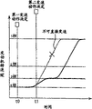
Fig. 9 is illustrated under the control of gear change control device shown in Fig. 7, in the 4-3 of automatic transmission shift-down action and 4-2 shift-down action process, and the time diagram that clutch-apply pressure and engine speed NE change;
Figure 10 is the flow chart of control function that the gear change control device of Fig. 7 is shown, and these functions are carried out in the speed Control process based on the decision of first gear shifting operation;
Figure 11 is illustrated under the situation with the middle gear of a plurality of candidates the view of the example of making decision in the step S5 of Figure 10;
Figure 12 is a part of flow chart that illustrates according to the control function of the gear change control device of second embodiment of the invention, and these functions are carried out in the speed Control process based on the decision of first gear shifting operation;
Figure 13 is the view that engine speed NE variation in a second embodiment is shown;
Figure 14 is a part of flow chart that illustrates according to the control function of the gear change control device of third embodiment of the invention, and these functions are carried out in the speed Control process based on the decision of first gear shifting operation;
Figure 15 is illustrated in the view that engine speed NE changes among the 3rd embodiment.
Description of reference numerals:
14: automatic transmission
90: electric control device
120: gear change control device
122: the gear shifting operation determination device
124: the speed Control implementing apparatus
132: speed change pattern storage device (storage device)
C0, C1, C2, C3: clutch (friction engagement device)
B1, B2, B3: break (friction engagement device)
Step S8: selection device
Embodiment
Describe the preferred embodiments of the present invention below with reference to accompanying drawings in detail.
Embodiment 1
Schematic representation with reference to Fig. 1, show the horizontal arrangement type Vehicular drive system that is applicable to FF vehicle (engine behind front wheel f-w-d vehicle), for example, wherein the output such as the motor 10 of petrol engine or other internal-combustion engine is passed to not shown driving wheel (front-wheel) by power transmitting deice, and this power transmitting deice comprises torque-converters 12, automatic transmission 14 and differential gear mechanism 16.Torque-converters 12 comprises: the pump impeller 20 that links to each other with the bent axle 18 of motor 10; The turbine 24 that links to each other with the input shaft 22 of automatic transmission 14; Be fixed to the guide wheel 30 on the fixed component of housing 28 forms via overrunning clutch 26; And be used for via buffer (not shown) direct-coupled lock-up clutch 32 between bent axle 18 and input shaft 22.Mechanical oil pump 21 such as gear pump links to each other with pump impeller 20, and is driven by motor 10 with pump impeller 20, is used to operate the working oil of automatic transmission 14 and lubricated drive system with pressurization.Motor 10 usefulness act on the actuating force source that makes vehicle driving, and torque-converters 12 is as fluid-operated coupling device.
First planetary gear system 40 of above-mentioned and input shaft 22 coaxial arrangement and second planetary gear system 42, clutch C0, C1 and C2, break B1 and B2 and overrunning clutch F1 constitute the main speed changing portion MG with four forward gearss and a reverse gear; And the third line star gear device 46 of above-mentioned and countershaft 44 coaxial arrangement, clutch C3, break B3 and overrunning clutch F2 constitute the secondary speed changing portion of low speed transmission unit U/D form.In main speed changing portion MG, input shaft 22 links to each other with the planet carrier K2 of second planetary gear system 42, the sun gear S1 of first planetary gear system 40 and the sun gear S2 of second planetary gear system 42 respectively with C2 by clutch C0, C1.The planet carrier K2 of the gear ring R1 of first planetary gear system 40 and second planetary gear system 42 is connected with each other, and the planet carrier K1 of the gear ring R2 of second planetary gear system 42 and first planetary gear system 40 is connected with each other.The sun gear S2 of second planetary gear system 42 is fixed on the fixed component of housing 28 forms via break B1, and the gear ring R1 of first planetary gear system 40 is fixed on the fixed component of housing 28 forms via break B2.Overrunning clutch F1 is arranged between the fixed component of the planet carrier K2 of second planetary gear system 42 and housing 28 forms.The second counter shaft gear G2 that is fixed to the first counter shaft gear G1 on the planet carrier K1 of first planetary gear system 40 and is fixed on the gear ring R3 of the third line star gear device 46 is engaged with each other.In the U/D of low speed transmission unit, the planet carrier K3 and the sun gear S3 of the third line star gear device 46 are connected with each other via clutch C3, and break B3 and overrunning clutch F2 are arranged between the fixed component of sun gear S3 and housing 28 forms each other side by side.
Above-mentioned clutch C0, C1, C2, C3 (being referred to as " clutch ") and break B1, B2, B3 (being referred to as " break ") are the hydraulic operation friction engagement device such as multidisc clutch or band brake, and they engage by hydraulic actuator.These friction engagement devices are according to the operation of hand control valve (not shown), solenoid valve S1-S5 by hydraulic control circuit 98 (shown in Fig. 3) and the excitation of linear solenoid valve SL1, SL2, SLU optionally engage with non-excitation and separate, with shift position according to the current selection of speed change lever 72 (shown in Fig. 3), optionally set up one of five forward gearss of automatic transmission 14, reverse gear and neutral gear, as shown in Figure 2.In Fig. 2, first grade to the 5th grade of " 1st " to " 5th " expression, they are forward gearss; " O " and " X " represents the jointing state and the separated state of clutch, break or overrunning clutch respectively; And the jointing state of " Δ " expression overrunning clutch when vehicle drive force transmits on direction of advance.As example, speed change lever 72 has Parking position P, reverse gear position R, neutral position N and advance gear D, 4,3,2, L, and can be according to the speed change path operations shown in Fig. 4 to these positions selected.When speed change lever 72 was placed in Parking position P or neutral position N, the non-driving gear that automatic transmission 14 is placed in the neutral position form did not wherein transmit vehicle drive force.At Parking position P, driving wheel is by mechanical halting mechanism (not shown) machinery locking, to prevent the rotation of driving wheel.
With reference to the block diagram of Fig. 3, show the control system that is arranged on the vehicle in order to motor 10 shown in the control graph 1 and automatic transmission 14.In this control system, the operation amount Acc of accelerator pedal 50 is detected by accelerator operation amount sensor 51.Accelerator pedal 50 is exported corresponding amount by the vehicle driver's operation and the motor of driver's expectation.In this respect, accelerator pedal 50 is as the manually-operable acceleration components, and accelerator-pedal operation amount Acc represents the motor output expected.Be furnished with electronic throttle 56 in the suction tude of motor 10, its aperture θ th is changed according to throttle opening command value TA by throttle actuator 54.Throttle opening command value TA is corresponding with aperture θ th, and mainly on accelerator-pedal operation amount Acc basis according to expression accelerator-pedal operation amount Acc and target throttle valve command value TA
*Between predetermined relationship collection of illustrative plates and determine, as example should the relation as shown in Figure 5.Target throttle valve command value TA
*TA increases along with the increase of accelerator-pedal operation amount Acc with the throttle opening command value, makes the aperture θ th of closure increase to increase motor output.
This control system also comprises: the engine rotation speed sensor 58 that is used for the rotational speed N E of detection of engine 10; The air inflow sensor 60 that is used for the air inflow Q of detection of engine 10; Be used for the complete shut-down state (engine idle state) of detected electrons closure 56 and the throttle sensor that has Idle Switch 60 of aperture θ th; Be used to detect countershaft 44 rotational speed N of reflection vehicle velocity V
OUTVehicle speed sensor 66; The cooling-water temperature sensor 68 that is used for the coolant water temperature Tw of detection of engine 10; Be used to detect the serviceability of brake petal and the brake switch 70 of non-operating state; Be used to detect speed change lever 72 current selected location P
SHMLP sensor 74; Be used to detect the secondary speed NT (rotational speed N of input shaft 22
IN) turbine speed sensor 76; Being used to detect hydraulic control circuit 98 interior working oil temperature is the warm T of AT oil
OILTOTS 78; And the counter shaft gear speed probe 80 that is used to detect the first counter shaft gear G1 rotational speed N C.Electric control device 90 receives expression engine speed NE, air inflow Q, throttle th, vehicle velocity V, engine coolant temperature Tw, brake petal operation NOR operation state, the speed change lever 72 current selected location P from these sensors
SH, secondary speed NT, gearbox oil temperature T
OILSignal with counter shaft gear speed NC.Brake switch 70 is to be operated or to unclamp and the ON-OFF switch of opening and closing according to the brake petal that is used for service braking sytem.
Gear change control device 120 comprises gear shifting operation determination device 122 and speed Control implementing apparatus 124.The speed change boundary line (speed change boundary line collection of illustrative plates) that is stored in the speed change condition storage device 130 as the speed change condition during gear shifting operation determination device 122 is arranged on the basis of actual accelerator-pedal operation amount Acc and actual vehicle speed V according to Fig. 6 is determined the target gear of automatic transmission 14 every now and then, and judges whether the gear of the current foundation of automatic transmission is different from determined target gear.On the other hand, speed Control implementing apparatus 124 is arranged to implement the speed Control of automatic transmission 14 speed changes to determined target gear being judged as current gear when being different from determined target gear.
Even implement in the process of speed Control based on first gear shifting operation decision of gear shifting operation determination device 122 at speed Control implementing apparatus 124, gear shifting operation determination device 122 is also determined the target gear every now and then.In Fig. 6, solid line is represented shift-up boundary line, and dotted line is represented shift-down boundary line.These upgrade and shift-down boundary line is determined to be and makes and to reduce or when accelerator-pedal operation amount Acc increases, automatic transmission 14 speed changes are extremely had than transmission ratio (input speed N than current gear when vehicle velocity V
IN/ output speed N
OUT) gear.In this Fig. 6, " 1 " to " 5 " represents first grade to the 5th grade respectively.Shift-up boundary line is determined to be and makes vehicle drive force along with the increase of accelerator-pedal operation amount Acc suitably increases, and shift-down boundary line is determined to be and makes vehicle drive force suitably increase along with the increase of brake petal operation amount and reducing of accelerator-pedal operation amount Acc.
When gear shifting operation determination device 122 was made the decision of second gear shifting operation in the process of automatic transmission 14 based on first gear shifting operation decision enforcement speed Control, speed Control implementing apparatus 124 was implemented the speed Control based on the decision of second gear shifting operation immediately.In this case, implement speed Control according to the flow chart of Figure 10.
In order to implement, select the combination of single speed change pattern or a plurality of speed change patterns among a plurality of speed change patterns that speed Control implementing apparatus 124 is at first stored from speed change pattern storage device 132 with the speed Control of automatic transmission 14 speed changes to the target gear.Speed Control implementing apparatus 124 is opened (excitation) or is closed the solenoid valve S1-S5 of (non-excitation) hydraulic control circuit 98, optionally engaging and cut-off clutch C and break B, thereby set up based on the gear of selected single speed change pattern or set up the gear that makes up based on selected speed change pattern in turn.Speed Control implementing apparatus 124 is controlled continuously and is applied to the magnitude of current of linear solenoid valve SL1, SL2 and SLU, thereby prevents automatic transmission 14 because vehicle drive force changes the speed change impact that causes, or the deterioration of clutch and brake friction parts durability.
The speed change pattern information of above-mentioned a plurality of speed change patterns of speed change pattern storage device 132 storage representations and required speed change time of each speed change pattern.Fig. 8 illustrates the example of the speed change pattern information of the pattern information form that lowers category of representing the pattern that lowers category.Each speed change pattern of being stored is that automatic transmission 14 can more easily realize and not have gear shifting operation or the gear shifting operation combination that speed change is impacted.The speed change pattern of being stored is determined according to the concrete structure of automatic transmission 14.The pattern of lowering category of being stored among Fig. 8 comprises: speed change is to the single-stage speed change pattern (No.1-4) of adjacent gear; Stepless change is to the multiple variable speed pattern (No.7,9,10) of non-adjacent gear; Stride across the trip stop speed change pattern (No.5 and 6) of one or more gear speed changes; And the combination (No.8) of single-stage speed change pattern, multiple variable speed pattern or trip stop speed change pattern.Speed change pattern storage device 132 is gone back the upgrade pattern information (not shown) that upgrades of pattern of storage representation.Based on the combination of the gear shifting operation of each speed change pattern of being stored or gear shifting operation can by in the control friction engagement device (clutch C and break B) only one or two is realized.The time that the required speed change time of speed change pattern is predetermined length, but can on such as the vehicle-state parameter basis of value of vehicle acceleration and deceleration value, determine.Speed change pattern storage device 132 is corresponding to storage device, and speed change pattern storage device 132 and speed change condition storage device 130 can provide in above-mentioned RAM or ROM.
With reference to the time diagram among Fig. 9, wherein show under the control of gear change control device 120, in the 4-3 shift-down action of automatic transmission 14 and the 4-2 shift-down action process, the variation of clutch-apply pressure and engine speed NE.When making the gear shifting operation decision at time point t0, the speed Control that determines based on this gear shifting operation begins.In this speed Control, the order hydraulic pressure value of linear solenoid valve SL solenoidoperated cluthes activating pressure was once sharply raising and had been reduced to the level that begins the preceding high prearranging quatity of level than speed Control then.As shown in Figure 2,4-3 shift-down action and 4-2 shift-down action all realize by engaging clutch C1.After the zero hour, working oil is provided for clutch C1 in the speed Control of implementing 4-3 or 4-2 shift-down action, and at time point t1 promptly when the actual hydraulic pressure of clutch C1 equals order hydraulic pressure value, this clutch C1 is full of working oil.Like this, clutch C1 is placed in adjustable in pressure nodular attitude, does not have significant time lag from zero hour of speed Control.Under adjustable in pressure nodular attitude, the clutch-apply pressure can regulate.
For realizing needing the hydraulic pressure (not shown among Fig. 9) of the friction engagement device of separation to be lowered, make that engine speed NE begins to raise, as shown in Figure 9 based on the speed Control of this gear shifting operation decision.The hydraulic pressure rate of descent of the friction engagement device that need to separate is controlled such that the initial stage rising gradient that the initial stage rising gradient ratio 4-2 of engine speed NE in 4-3 shift-down action process lowers category in the process relaxes.For realizing that the friction engagement device that the 4-3 shift-down action needs to separate is break B1, for realizing that the friction engagement device that the 4-2 shift-down action needs to separate is clutch C0.
The hydraulic pressure rate of descent of the friction engagement device that need separate and the rising gradient of engine speed NE are controlled as described above, to be elevated to the determined level of setting up by shift-down action of gear at engine speed NE, promptly, before the synchronous speed of clutch C1, make the hydraulic pressure that needs oncoming clutch C1 be elevated to the level that allows clutch C1 synchronization control.Difference before and after the single-stage 4-3 shift-down action between the engine speed value NE is less than the difference between the engine speed value NE before and after the two-stage 4-2 shift-down action, thereby engine speed NE raises with the gradient that relaxes in single-stage 4-3 shift-down action, has time enough to raise with the hydraulic pressure that allows clutch C1.On the other hand, in two-stage 4-2 shift-down action, because hydraulic pressure can raise with low relatively speed at an easy rate after the hydraulic pressure that raises relatively fast reaches a little less than the level of synchronization of clutch C1, thereby the hydraulic pressure of clutch C1 at first raises with higher relatively speed.
The synchronization control of 4-3 shift-down action begins at time point t2, and the synchronization control of 4-2 shift-down action begins at time point t3.The time point that synchronization control begins can detect at present engine tachometer value NE with on the rising gradient basis of difference between the engine speed value NE after the shift-down action of the extremely new gear of speed change and engine speed NE.After detecting the time point that synchronization control begins, order hydraulic pressure value raises with the pre-gradient of determining that relaxes.The rising gradient that order hydraulic pressure value relaxes is determined to be and reduces automatic transmission 14 because the timing of the friction engagement device separating action that will separate and want the inconsistent speed change impact that causes between the timing of oncoming clutch C1 joint action, and this inconsistent meeting produces owing to the variation of hydraulic control characteristic and the detection mistake of engine rotation speed sensor 58.
The flow chart of Figure 10 illustrates the control function of gear change control device 120, and these control functions are carried out in the speed Control process based on the decision of first gear shifting operation.The control routine of Figure 10 is to carry out every now and then short predetermined cycle time.In the control routine of Figure 10, judge whether to make the decision of second gear shifting operation at step S1.This judgement is made based on the speed change boundary line of Fig. 6.If in step S1, make negative evaluation, the then executive termination of control routine.If because vehicle driving conditioned disjunction vehicle driver's operation changes, the target gears that automatic transmission 14 is selected recently are different from based on first gear shifting operation and determine selected target gear, then make affirmative determination in step S1.This step S1 is corresponding to above-mentioned gear shifting operation determination device 122, and it is arranged to make with automatic transmission 14 speed changes to the gear shifting operation decision of selected gear recently.
If make affirmative determination in step S1, then control flow forwards step S2 to, to judge whether and automatic transmission 14 direct changes extremely can not be determined nearest selected target gear based on second gear shifting operation.Whether this judgement is made greater than the upper limit quantity (for example, two) of the friction engagement device that can control simultaneously according to setting up the friction engagement device quantity that nearest selected target gear should control simultaneously.If in step S2, make negative evaluation, promptly, if automatic transmission 14 can direct change to nearest selected target gear, then control flow forwards step S3 to end the speed Control based on the decision of first gear shifting operation, forwards step S4 then to implement automatic transmission 14 speed changes to the speed Control that determines selected target gear based on second gear shifting operation.
If make affirmative determination in step S2, then control flow forwards step S5 to, to judge whether to exist the middle gear of a plurality of candidates.Gears are to be different from nearest selected target gear and automatic transmission 14 can direct change gear extremely in the decisive time of step S1 in the middle of these candidates.If make negative evaluation in step S5, that is, if having only a middle gear of automatic transmission energy direct change candidate extremely, then control flow forwards step S6 to, so that gear in the middle of this candidate is defined as middle gear.
If make affirmative determination in step S5, then control flow forwards step S7 to, gear in the middle of being defined as with of setting up under the situation of engine speed NE variable quantity maximum among the gear in the middle of will the candidate.The variable quantity maximum of engine speed NE means to be finished engine speed NE to change the required time the longest, thereby clutch-apply pressure has time enough to raise.Therefore, clutch-apply pressure can raise with gear in the middle of setting up with the gradient that relaxes most, impacts thereby can reduce speed change.
With reference to Figure 11, show a kind of example of in step S5, making the situation of the affirmative determination that has the middle gear of a plurality of candidates.In this example, make first gear shifting operation decision of implementing the 4-3 shift-down action constantly at t0, and make second gear shifting operation decision of implementing the 4-1 shift-down action constantly at t1, be engraved in during t1 before the moment that engine speed NE begins to raise.That is, selected target gear constantly becomes first grade from third gear at t1.Attention is reduced to first grade 4-1 shift-down action from fourth speed needs the separating action of clutch C0 and break B1 and the joint action of clutch C1, promptly, the friction engagement device quantity that should control simultaneously is greater than predetermined upper limit quantity, thereby can not implement the 4-1 shift-down action of direct change to the first grade.Therefore, in this example, in step S2, make affirmative determination, and control flow forwards step S5 to.
In the example of Figure 11, as the result of first gear shifting operation decision, the hydraulic pressure of break B1 begins to reduce and the hydraulic pressure of clutch C1 begins to raise, though this figure does not represent the reduction and the rising of these hydraulic pressure.The t1 that does not also begin in the actual rising of engine speed NE can make this hydraulic pressure raise then, and reduce the hydraulic pressure of clutch C0 rather than break B1 constantly by the reduction of ending break B1 hydraulic pressure, and implements the shift-down action of speed change to the second grade.It shall yet further be noted that the speed Control that can continue, that is, implement the shift-down action of speed change to third gear based on the decision of first gear shifting operation.Like this, at t1 constantly, there is the middle gear of two candidates, that is, and second grade and third gear.But the 4-2 shift-down action causes the bigger variable quantity of engine speed NE than 4-3 shift-down action.Thereby in step S7, second grade is confirmed as middle gear.
Subsequently, at step S8 corresponding to selection device, select to allow in the shortest time therefrom among the speed change pattern of being stored from speed change pattern storage device 132 between the gear speed change to the single speed change pattern or the speed change pattern combination of the gear shifting operation that determines selected target gear based on second gear shifting operation.In the example of Figure 11, middle gear is second grade and the target gear is first grade, so select the single-stage 2-1 pattern that lowers category.But if the gear direct change is to the gear shifting operation of target gear between can not implementing therefrom, then this gear shifting operation is implemented according to the combination of a plurality of speed change patterns.If exist two or more be used for therefrom between the gear speed change to the combination of the speed change pattern of target gear, then select one of the shortest optimum of total speed change time among these combinations.For this reason, on the speed change time basis of the speed change pattern that speed change pattern storage device 132 is stored, calculate all combination total speed change times separately.If middle gear is a fourth speed, then there are four kinds of speed change pattern combinations.As shown in Figure 8, these four kinds are combined as: (1) 4-3 pattern and 3-1 pattern that lowers category that lowers category; (2) 4-3 pattern, 3-2 pattern and the 2-1 pattern that lowers category that lowers category that lowers category; (3) two-stage 4-3-2 pattern and the 2-1 pattern that lowers category that lowers category; And (4) 4-2 pattern and 2-1 pattern that lowers category that lowers category.In this case, select the shortest a kind of of total speed change time of being calculated among these four kinds of combinations.
Then, control flow forwards step S9 to, to end the speed Control based on the decision of first gear shifting operation, forwards step S10 then to, to implement to be based upon the speed Control of determined middle gear among step S6 or the step S7.In following step S11, the suitably opening and closing of solenoid valve S1-S5 of hydraulic control circuit 98, to engage and to separate suitable clutch C and break B, thereby make automatic transmission gear shift based on one of selected speed change pattern combination in step S8, be applied to magnitude of current on linear solenoid valve SL1, SL2 and the SLU simultaneously by continuous control, engaging hydraulic pressure with clutch C that separates and break B with control.
In step S12, make the judgement whether automatic transmission 14 is finished based on the speed change of discussion speed change pattern.This judgement is made on the command signal basis of solenoid valve S1-S5 and linear solenoid valve SL1, SL2, SLU.If the speed change based on the discussion speed change pattern is finished, then control flow forwards step S13 to.
In step S13, judge whether the target gear is set up.This judgement is made on the command signal basis of solenoid valve S1-S5.If the target gear is set up, the then once execution loop ends of this control routine.If the target gear is also set up, then repeating step S11 and subsequent step are to make automatic transmission gear shift based on next speed change pattern.
Below, the second embodiment of the present invention will be described.In the following description, identical reference character is used to the element of representing that different embodiments are common.
Second embodiment and first embodiment's difference only is to be carried out and control function shown in Figure 12 by gear change control device 120, Figure 12 is a part that illustrates according to the flow chart of the control function of the gear change control device 120 of second embodiment of the invention, and these control functions are carried out in the speed Control process based on the decision of first gear shifting operation.Unique step shown in Figure 12 replaces the step S7 among Figure 10.That is, there are a plurality of candidates middle gear, then execution in step S7-1 if in the step S5 of Figure 10, judge.
In this step S7-1, one that can set up in the shortest time among the gear in the middle of the candidate is confirmed as middle gear.As with Figure 11, Figure 13 is illustrated in that t0 makes first gear shifting operation decision of implementing the 4-3 shift-down action constantly and makes constantly at t1 and to implement speed change to the situation as second gear shifting operation decision of first grade speed change of target gear, wherein is engraved in during t1 before the moment that engine speed NE begins to raise.The same with the example among Figure 11, in the example of Figure 13, there are two candidates middle gear, i.e. second grade and third gear.Figure 13 also illustrates the 4-2 shift-down action, is used for comparing with the 4-3 shift-down action.As shown in Figure 13, third gear can be set up in the shorter time than second grade.Therefore, in step S7-1, gear in the middle of third gear is confirmed as.The required speed change time calculates on the speed change pattern information basis that speed change pattern storage device 132 is stored.
In a second embodiment, can in the shortest time, set up among the gear in the middle of a plurality of candidates one be confirmed as in the middle of gear, middle gear can promptly be set up, thus setting up the required time of target gear also can shorten.
Though because third gear can be set up in the shorter time than second grade, thereby second embodiment be arranged to third gear be defined as in the middle of gear, but the hydraulic operation parameter that depends on the friction engagement device that will engage is set up second grade of required time may be shorter than and set up the required time of third gear.For example, want oncoming clutch to want oncoming clutch not simultaneously with implementing the 4-2 shift-down action in enforcement 4-3 shift-down action, foundation enforcement 4-3 shift-down action is wanted the adjustable in pressure nodular attitude needed time of oncoming clutch may be longer than foundation and is implemented the adjustable in pressure nodular attitude needed time that the 4-2 shift-down action is wanted oncoming clutch.In this case, set up second grade of required time and be shorter than and set up the required time of third gear by increasing the initial stage rising gradient of engine speed NE in 4-2 shift-down action process, can making.Because the difference before and after the 4-2 shift-down action between the engine speed value NE raises with the gradient that relaxes after engine speed NE reaches synchronous speed even as big as allowing engine speed NE, thereby the initial stage rising gradient of engine speed NE is bigger in 4-2 shift-down action process.
With reference to Figure 14 the third embodiment of the present invention is described below, Figure 14 illustrates the part according to the flow chart of the control function of the gear change control device 120 of third embodiment of the invention, and these control functions are carried out in the speed Control process based on the decision of first gear shifting operation.Unique step shown in Figure 14 replaces the step S7 among Figure 10.That is, there are a plurality of candidates middle gear, then execution in step S7-2 if in the step S5 of Figure 10, judge.
In this step S7-2, one that sets up under the situation of the variable quantity minimum of engine speed NE on the direction of gear in the middle of setting up among the gear in the middle of a plurality of candidates is confirmed as middle gear.In the example of Figure 15, make first gear shifting operation decision of implementing the 4-3 shift-down action constantly at t0, implement speed change to second gear shifting operation decision and make constantly as first grade speed change of target gear at the t1 that engine speed NE raises slightly.
If t1 constantly direct change to the gear shifting operation of third gear or second grade be possible, then third gear is set up with the engine speed NE variable quantity than second grade littler.Therefore, in step S7-2, gear in the middle of third gear is confirmed as.The 3rd embodiment is applicable to 4-3 shift-down action and the automatic transmission of 4-2 shift-down action by separating identical friction engagement device and realizing by the friction engagement device that joint has nothing in common with each other.
In the 3rd embodiment, one that sets up under the situation of the variable quantity minimum of engine speed NE on the direction of gear in the middle of setting up among the gear in the middle of a plurality of candidates is confirmed as middle gear, middle gear can promptly be set up, thereby setting up the required time of target gear also can shorten.
Though above only presented for purpose of illustration the property purpose describe embodiments of the invention in detail with reference to accompanying drawing, be to be understood that the various modification that the present invention can adopt with those skilled in the art and improve and implement.
Claims (2)
1. shift control apparatus, described shift control apparatus is used to control and has that gear ratio has nothing in common with each other and by optionally engaging the automatic transmission of a plurality of gears that a plurality of friction engagement devices set up, make the speed Control of described automatic transmission gear shift to the target gear that determines based on first gear shifting operation is switched to the speed Control of described automatic transmission gear shift to the target gear that determines based on second gear shifting operation, described second gear shifting operation decision is to make in the speed Control process based on described first gear shifting operation decision, and described shift control apparatus is characterised in that and comprises:
Speed-change control device; When can not be with described automatic transmission direct change during to the target gear that determines based on described second gear shifting operation; Described speed-change control device can operate to be used for described automatic transmission can be defined as by one of direct change gear extremely in the described second gear shifting operation decisive time the middle gear of described automatic transmission; And after setting up described middle gear, implement the speed Control of described automatic transmission gear shift to the target gear that determines based on described second gear shifting operation
And wherein said gear change control device is set up described automatic transmission among the described second gear shifting operation decisive time can be by direct change described gear extremely under the situation of engine speed change amount maximum a gear be defined as described in the middle of gear.
2. shift control apparatus according to claim 1 is characterized in that also comprising:
Speed change pattern storage device, described speed change pattern storage device are used to store the speed change time of a plurality of speed change patterns and described a plurality of speed change patterns of described automatic transmission; With
Selection device, when existence allows a plurality of speed change patterns of described automatic transmission from described middle gear speed change to the gear shifting operation of the target gear that determines based on described second gear shifting operation to make up, described selection device can be operated to be used for obtaining described a plurality of speed change pattern combination total speed change time separately on the basis of the described speed change time that described speed change pattern storage device is stored, and select the shortest one of total speed change time among the combination of described speed change pattern
And wherein said gear change control device is based on being implemented the speed Control of described automatic transmission from described middle gear speed change to described target gear by the selected speed change pattern combination of described selection device.
Applications Claiming Priority (2)
| Application Number | Priority Date | Filing Date | Title |
|---|---|---|---|
| JP2004325958A JP4639760B2 (en) | 2004-11-10 | 2004-11-10 | Shift control device for automatic transmission |
| JP325958/2004 | 2004-11-10 |
Related Child Applications (1)
| Application Number | Title | Priority Date | Filing Date |
|---|---|---|---|
| CN2008101706168A Division CN101392829B (en) | 2004-11-10 | 2005-11-08 | Shift control apparatus for automatic transmission |
Publications (2)
| Publication Number | Publication Date |
|---|---|
| CN101091076A CN101091076A (en) | 2007-12-19 |
| CN100529479C true CN100529479C (en) | 2009-08-19 |
Family
ID=36336597
Family Applications (2)
| Application Number | Title | Priority Date | Filing Date |
|---|---|---|---|
| CNB2005800451857A Expired - Fee Related CN100529479C (en) | 2004-11-10 | 2005-11-08 | Shift controller of automatic transmission |
| CN2008101706168A Expired - Fee Related CN101392829B (en) | 2004-11-10 | 2005-11-08 | Shift control apparatus for automatic transmission |
Family Applications After (1)
| Application Number | Title | Priority Date | Filing Date |
|---|---|---|---|
| CN2008101706168A Expired - Fee Related CN101392829B (en) | 2004-11-10 | 2005-11-08 | Shift control apparatus for automatic transmission |
Country Status (6)
| Country | Link |
|---|---|
| US (1) | US7374512B2 (en) |
| JP (1) | JP4639760B2 (en) |
| KR (1) | KR100882170B1 (en) |
| CN (2) | CN100529479C (en) |
| DE (1) | DE112005002753B4 (en) |
| WO (1) | WO2006051928A1 (en) |
Families Citing this family (20)
| Publication number | Priority date | Publication date | Assignee | Title |
|---|---|---|---|---|
| DE102006026600A1 (en) * | 2006-06-08 | 2007-03-29 | Zf Friedrichshafen Ag | Drive train operating method for motor vehicle, involves providing automatic transmission with five switching units, in which one of switching units is opened or closed during implementation of two stepping and/or shifting operations |
| DE102006026599A1 (en) * | 2006-06-08 | 2007-03-22 | Zf Friedrichshafen Ag | Method for use of automatic transmission gear, comprises interlaced performance of consecutive gear switch actions as multiple switches |
| JP4725450B2 (en) * | 2006-07-31 | 2011-07-13 | トヨタ自動車株式会社 | Control device for automatic transmission |
| JP4420007B2 (en) * | 2006-10-13 | 2010-02-24 | トヨタ自動車株式会社 | Automatic transmission range switching device |
| JP4349464B2 (en) * | 2008-03-13 | 2009-10-21 | トヨタ自動車株式会社 | Vehicle drive device |
| JP4774108B2 (en) * | 2009-03-02 | 2011-09-14 | 日産自動車株式会社 | Control device for automatic transmission |
| JP4970480B2 (en) * | 2009-03-06 | 2012-07-04 | 日産自動車株式会社 | Control device for automatic transmission |
| JP4907680B2 (en) * | 2009-03-06 | 2012-04-04 | 日産自動車株式会社 | Control device for automatic transmission |
| JP2010209947A (en) * | 2009-03-06 | 2010-09-24 | Nissan Motor Co Ltd | Control apparatus for automatic transmission |
| JP4907681B2 (en) * | 2009-03-06 | 2012-04-04 | 日産自動車株式会社 | Control device for automatic transmission |
| DE102010028762A1 (en) * | 2010-05-07 | 2011-11-10 | Zf Friedrichshafen Ag | Device for determining an operating state of at least one bidirectionally actuable hydraulic adjusting device of a switching element of a transmission device |
| US9026327B2 (en) * | 2012-05-02 | 2015-05-05 | GM Global Technology Operations LLC | Method and apparatus for executing a shift path to a target powertrain state |
| US9217502B2 (en) * | 2013-01-17 | 2015-12-22 | Stanley Wierzbowski | Electronic transmission control system |
| DE102013003520A1 (en) * | 2013-03-04 | 2014-09-04 | Getrag Getriebe- Und Zahnradfabrik Hermann Hagenmeyer Gmbh & Cie Kg | Control method for a dual-clutch transmission |
| JP5758430B2 (en) * | 2013-04-03 | 2015-08-05 | 本田技研工業株式会社 | Control device for automatic transmission |
| JP6014554B2 (en) * | 2013-06-05 | 2016-10-25 | 本田技研工業株式会社 | Power transmission device |
| US9371065B2 (en) * | 2014-03-20 | 2016-06-21 | GM Global Technology Operations LLC | Method of controlling a transmission |
| JP6465081B2 (en) * | 2016-07-20 | 2019-02-06 | トヨタ自動車株式会社 | Control device for automatic transmission |
| JP6423393B2 (en) * | 2016-07-28 | 2018-11-14 | トヨタ自動車株式会社 | Control device for automatic transmission |
| US10364884B2 (en) * | 2017-03-02 | 2019-07-30 | Honda Motor Co., Ltd. | Gear shift control device, a vehicle using the same, and gear shift control method |
Citations (3)
| Publication number | Priority date | Publication date | Assignee | Title |
|---|---|---|---|---|
| JP2001227635A (en) * | 2000-02-10 | 2001-08-24 | Aisin Aw Co Ltd | Automatic transmission |
| JP2002130454A (en) * | 2000-10-24 | 2002-05-09 | Honda Motor Co Ltd | Control device for automatic transmission |
| CN1475684A (en) * | 2002-06-13 | 2004-02-18 | 丰田自动车株式会社 | Shifting controller and controlling method for automatic speed variator |
Family Cites Families (10)
| Publication number | Priority date | Publication date | Assignee | Title |
|---|---|---|---|---|
| JP2924014B2 (en) * | 1989-11-13 | 1999-07-26 | トヨタ自動車株式会社 | Shift control method for automatic transmission |
| US5203234A (en) | 1989-11-13 | 1993-04-20 | Toyota Jidosha Kabushiki Kaisha | Automatic transmission |
| US5233525A (en) * | 1990-08-28 | 1993-08-03 | Case Corporation | Electronic control for transmission gear skip shift |
| JP3036919B2 (en) * | 1991-10-09 | 2000-04-24 | アイシン・エィ・ダブリュ株式会社 | Control device for automatic transmission |
| JP3301344B2 (en) | 1997-04-09 | 2002-07-15 | アイシン・エィ・ダブリュ株式会社 | Transmission control device for automatic transmission |
| US6149545A (en) * | 1999-01-14 | 2000-11-21 | Eaton Corporation | Automated transmission upshift control |
| US6113516A (en) * | 1999-01-14 | 2000-09-05 | Eaton Corporation | Adaptive automated transmission upshift control |
| US6066071A (en) * | 1999-01-15 | 2000-05-23 | Eaton Corporation | Automated transmission downshift control |
| US6851328B2 (en) * | 2002-04-18 | 2005-02-08 | Kubota Corporation | Control apparatus for transmission |
| JP4752196B2 (en) | 2004-06-01 | 2011-08-17 | トヨタ自動車株式会社 | Shift control device for automatic transmission for vehicle |
-
2004
- 2004-11-10 JP JP2004325958A patent/JP4639760B2/en not_active Expired - Fee Related
-
2005
- 2005-11-08 KR KR1020077013139A patent/KR100882170B1/en not_active IP Right Cessation
- 2005-11-08 US US11/268,588 patent/US7374512B2/en not_active Expired - Fee Related
- 2005-11-08 WO PCT/JP2005/020778 patent/WO2006051928A1/en not_active Application Discontinuation
- 2005-11-08 CN CNB2005800451857A patent/CN100529479C/en not_active Expired - Fee Related
- 2005-11-08 DE DE112005002753T patent/DE112005002753B4/en not_active Expired - Fee Related
- 2005-11-08 CN CN2008101706168A patent/CN101392829B/en not_active Expired - Fee Related
Patent Citations (3)
| Publication number | Priority date | Publication date | Assignee | Title |
|---|---|---|---|---|
| JP2001227635A (en) * | 2000-02-10 | 2001-08-24 | Aisin Aw Co Ltd | Automatic transmission |
| JP2002130454A (en) * | 2000-10-24 | 2002-05-09 | Honda Motor Co Ltd | Control device for automatic transmission |
| CN1475684A (en) * | 2002-06-13 | 2004-02-18 | 丰田自动车株式会社 | Shifting controller and controlling method for automatic speed variator |
Also Published As
| Publication number | Publication date |
|---|---|
| CN101392829A (en) | 2009-03-25 |
| JP2006138333A (en) | 2006-06-01 |
| JP4639760B2 (en) | 2011-02-23 |
| US7374512B2 (en) | 2008-05-20 |
| CN101392829B (en) | 2012-07-04 |
| DE112005002753T5 (en) | 2007-09-06 |
| DE112005002753B4 (en) | 2013-01-17 |
| WO2006051928A1 (en) | 2006-05-18 |
| KR20070086035A (en) | 2007-08-27 |
| US20060154780A1 (en) | 2006-07-13 |
| CN101091076A (en) | 2007-12-19 |
| KR100882170B1 (en) | 2009-02-06 |
Similar Documents
| Publication | Publication Date | Title |
|---|---|---|
| CN100529479C (en) | Shift controller of automatic transmission | |
| CN100498015C (en) | Automatic gear control device | |
| CN103978975B (en) | Control the method and system of the gearshift of user's request in motor vehicle driven by mixed power | |
| CN100526689C (en) | Shift control apparatus and shift control method of automatic transmission of vehicle | |
| US7505842B2 (en) | Method for configuring a transmission control for motor vehicles | |
| CN100497058C (en) | Method and device for controlling gear shift of mechanical transmission | |
| CN100434766C (en) | Automatic transmission control device | |
| CN101629628B (en) | Control device for vehicular automatic transmission | |
| JP4461997B2 (en) | Engine control device | |
| CN102361787B (en) | Driving force control device | |
| CN1289842C (en) | Automatic speed regulator hydraulic controller and controlling method for abrading connector thereof | |
| US20070117677A1 (en) | Shift control device of vehicular automatic transmission | |
| CN101874173B (en) | Automatic transmission control apparatus and method | |
| CN107792074A (en) | Control device and control method for vehicle | |
| CN104755815B (en) | The travel controlling system of vehicle | |
| CN101163907B (en) | Automatic gear control device | |
| CN101903688B (en) | Automatic transmission control apparatus and control method | |
| CN103299108B (en) | Vehicular control apparatus | |
| US7563198B2 (en) | Shift control device and shift control method of automatic transmission | |
| CN104769332A (en) | Vehicle travel control device | |
| CN101797919B (en) | Control device for vehicle drive device and control method for vehicle drive device | |
| CN100436891C (en) | Engine control device of power transmission device for vehicle | |
| CN105531512A (en) | Control device for continuously variable transmission | |
| CN101529130B (en) | Shift control device for industrial vehicle | |
| CN103939593A (en) | Gear shift control apparatus for vehicle |
Legal Events
| Date | Code | Title | Description |
|---|---|---|---|
| C06 | Publication | ||
| PB01 | Publication | ||
| C10 | Entry into substantive examination | ||
| SE01 | Entry into force of request for substantive examination | ||
| C14 | Grant of patent or utility model | ||
| GR01 | Patent grant | ||
| CF01 | Termination of patent right due to non-payment of annual fee |
Granted publication date: 20090819 Termination date: 20171108 |
|
| CF01 | Termination of patent right due to non-payment of annual fee |