CN100486021C - Cell stack for direct liquid feed fuel cell - Google Patents
Cell stack for direct liquid feed fuel cell Download PDFInfo
- Publication number
- CN100486021C CN100486021C CNB2006100771917A CN200610077191A CN100486021C CN 100486021 C CN100486021 C CN 100486021C CN B2006100771917 A CNB2006100771917 A CN B2006100771917A CN 200610077191 A CN200610077191 A CN 200610077191A CN 100486021 C CN100486021 C CN 100486021C
- Authority
- CN
- China
- Prior art keywords
- cathode
- direct liquid
- liquid supply
- fuel cell
- cell stack
- Prior art date
- Legal status (The legal status is an assumption and is not a legal conclusion. Google has not performed a legal analysis and makes no representation as to the accuracy of the status listed.)
- Expired - Fee Related
Links
Images


Classifications
-
- H—ELECTRICITY
- H01—ELECTRIC ELEMENTS
- H01M—PROCESSES OR MEANS, e.g. BATTERIES, FOR THE DIRECT CONVERSION OF CHEMICAL ENERGY INTO ELECTRICAL ENERGY
- H01M8/00—Fuel cells; Manufacture thereof
- H01M8/04—Auxiliary arrangements, e.g. for control of pressure or for circulation of fluids
- H01M8/04082—Arrangements for control of reactant parameters, e.g. pressure or concentration
- H01M8/04089—Arrangements for control of reactant parameters, e.g. pressure or concentration of gaseous reactants
- H01M8/04119—Arrangements for control of reactant parameters, e.g. pressure or concentration of gaseous reactants with simultaneous supply or evacuation of electrolyte; Humidifying or dehumidifying
- H01M8/04156—Arrangements for control of reactant parameters, e.g. pressure or concentration of gaseous reactants with simultaneous supply or evacuation of electrolyte; Humidifying or dehumidifying with product water removal
- H01M8/04171—Arrangements for control of reactant parameters, e.g. pressure or concentration of gaseous reactants with simultaneous supply or evacuation of electrolyte; Humidifying or dehumidifying with product water removal using adsorbents, wicks or hydrophilic material
-
- H—ELECTRICITY
- H01—ELECTRIC ELEMENTS
- H01M—PROCESSES OR MEANS, e.g. BATTERIES, FOR THE DIRECT CONVERSION OF CHEMICAL ENERGY INTO ELECTRICAL ENERGY
- H01M8/00—Fuel cells; Manufacture thereof
- H01M8/02—Details
-
- H—ELECTRICITY
- H01—ELECTRIC ELEMENTS
- H01M—PROCESSES OR MEANS, e.g. BATTERIES, FOR THE DIRECT CONVERSION OF CHEMICAL ENERGY INTO ELECTRICAL ENERGY
- H01M8/00—Fuel cells; Manufacture thereof
- H01M8/02—Details
- H01M8/0202—Collectors; Separators, e.g. bipolar separators; Interconnectors
- H01M8/0258—Collectors; Separators, e.g. bipolar separators; Interconnectors characterised by the configuration of channels, e.g. by the flow field of the reactant or coolant
- H01M8/0263—Collectors; Separators, e.g. bipolar separators; Interconnectors characterised by the configuration of channels, e.g. by the flow field of the reactant or coolant having meandering or serpentine paths
-
- H—ELECTRICITY
- H01—ELECTRIC ELEMENTS
- H01M—PROCESSES OR MEANS, e.g. BATTERIES, FOR THE DIRECT CONVERSION OF CHEMICAL ENERGY INTO ELECTRICAL ENERGY
- H01M8/00—Fuel cells; Manufacture thereof
- H01M8/10—Fuel cells with solid electrolytes
- H01M8/1009—Fuel cells with solid electrolytes with one of the reactants being liquid, solid or liquid-charged
-
- H—ELECTRICITY
- H01—ELECTRIC ELEMENTS
- H01M—PROCESSES OR MEANS, e.g. BATTERIES, FOR THE DIRECT CONVERSION OF CHEMICAL ENERGY INTO ELECTRICAL ENERGY
- H01M8/00—Fuel cells; Manufacture thereof
- H01M8/24—Grouping of fuel cells, e.g. stacking of fuel cells
- H01M8/241—Grouping of fuel cells, e.g. stacking of fuel cells with solid or matrix-supported electrolytes
-
- H—ELECTRICITY
- H01—ELECTRIC ELEMENTS
- H01M—PROCESSES OR MEANS, e.g. BATTERIES, FOR THE DIRECT CONVERSION OF CHEMICAL ENERGY INTO ELECTRICAL ENERGY
- H01M8/00—Fuel cells; Manufacture thereof
- H01M8/24—Grouping of fuel cells, e.g. stacking of fuel cells
- H01M8/2465—Details of groupings of fuel cells
- H01M8/2483—Details of groupings of fuel cells characterised by internal manifolds
-
- H—ELECTRICITY
- H01—ELECTRIC ELEMENTS
- H01M—PROCESSES OR MEANS, e.g. BATTERIES, FOR THE DIRECT CONVERSION OF CHEMICAL ENERGY INTO ELECTRICAL ENERGY
- H01M8/00—Fuel cells; Manufacture thereof
- H01M8/10—Fuel cells with solid electrolytes
- H01M8/1009—Fuel cells with solid electrolytes with one of the reactants being liquid, solid or liquid-charged
- H01M8/1011—Direct alcohol fuel cells [DAFC], e.g. direct methanol fuel cells [DMFC]
-
- Y—GENERAL TAGGING OF NEW TECHNOLOGICAL DEVELOPMENTS; GENERAL TAGGING OF CROSS-SECTIONAL TECHNOLOGIES SPANNING OVER SEVERAL SECTIONS OF THE IPC; TECHNICAL SUBJECTS COVERED BY FORMER USPC CROSS-REFERENCE ART COLLECTIONS [XRACs] AND DIGESTS
- Y02—TECHNOLOGIES OR APPLICATIONS FOR MITIGATION OR ADAPTATION AGAINST CLIMATE CHANGE
- Y02E—REDUCTION OF GREENHOUSE GAS [GHG] EMISSIONS, RELATED TO ENERGY GENERATION, TRANSMISSION OR DISTRIBUTION
- Y02E60/00—Enabling technologies; Technologies with a potential or indirect contribution to GHG emissions mitigation
- Y02E60/30—Hydrogen technology
- Y02E60/50—Fuel cells
Landscapes
- Life Sciences & Earth Sciences (AREA)
- Engineering & Computer Science (AREA)
- Manufacturing & Machinery (AREA)
- Sustainable Development (AREA)
- Sustainable Energy (AREA)
- Chemical & Material Sciences (AREA)
- Chemical Kinetics & Catalysis (AREA)
- Electrochemistry (AREA)
- General Chemical & Material Sciences (AREA)
- Fuel Cell (AREA)
Abstract
本发明公开了一种具有内部设有膜电极组件(MEAs)的结构的直接液体供应燃料电池的电池堆,每一膜电极组件具有在电极薄膜的任一侧上的阳极和阴极,这些膜电极组件被堆叠在一起,并使导电阳极板和导电阴极板分别形成为面对所述阳极和阴极,其中,所述阴极板包括多条平行的直流动通道,上表面具有与所述直流动通道的下表面同一平面的亲水部件被设置成垂直于所述阴极板的一端上的所述流动通道。在本发明的直接液体供应燃料电池的电池堆中,接触阴极的导电板的一端与不会阻塞形成于导电板中的空气通道的亲水部件相连,因此,产生在空气通道底部上的水滴容易被亲水部件吸收,并且这不会导致空气流动通道中出现压力损失。

The present invention discloses a stack of direct liquid supply fuel cells having a structure internally provided with membrane electrode assemblies (MEAs), each membrane electrode assembly having an anode and a cathode on either side of an electrode membrane, the membrane electrodes Assemblies are stacked together with a conductive anode plate and a conductive cathode plate formed to face the anode and the cathode respectively, wherein the cathode plate includes a plurality of parallel direct flow channels, an upper surface having a The lower surface of the coplanar hydrophilic member is arranged perpendicular to the flow channel on one end of the cathode plate. In the cell stack of the direct liquid supply fuel cell of the present invention, one end of the conductive plate contacting the cathode is connected to a hydrophilic member which does not block the air passage formed in the conductive plate, and therefore, water droplets generated on the bottom of the air passage are easily Absorbed by hydrophilic parts and this does not cause pressure loss in the air flow channels.
Description
技术领域 technical field
本发明涉及一种直接液体供应燃料电池的电池堆(direct liquid feed fuelcell stack),更具体地说,涉及一种具有防止由在阴极处产生的水所造成的氧流动通道阻塞的结构的直接液体供应燃料电池的电池堆。The present invention relates to a direct liquid feed fuel cell stack (direct liquid feed fuel cell stack), more particularly, to a direct liquid feed fuel cell stack having a structure to prevent blockage of oxygen flow channels caused by water generated at the cathode The stack that supplies the fuel cell.
背景技术 Background technique
直接液体供应燃料电池通过如甲醇或乙醇之类的有机燃料和如空气中的氧之类的氧化剂之间的电化学反应产生电。直接液体供应燃料电池具有高的比能量密度以及高的电流密度。另外,由于如甲醇之类的液体燃料被直接供给电池,直接供给燃料电池不需要如燃料重整器之类的外围装置,并能方便地存储和供给液体燃料。Direct liquid supply fuel cells generate electricity through an electrochemical reaction between an organic fuel, such as methanol or ethanol, and an oxidant, such as oxygen in air. Direct liquid supply fuel cells have high specific energy density as well as high current density. In addition, since liquid fuel such as methanol is directly supplied to the battery, the direct supply fuel cell does not require peripheral devices such as a fuel reformer and can store and supply the liquid fuel conveniently.
如图1所示,直接供给燃料电池的单元电池(unit cell)具有膜电极组件(MEA)结构,该结构具有设置在阳极2和阴极3之间的电解质膜1。阳极2包括用于供给和扩散燃料的扩散层22、进行燃料氧化反应的催化剂层21、以及电极支撑层23。阴极3也包括用于供给和扩散燃料的扩散层32、进行燃料还原反应的催化剂层31、以及电极支撑层33。As shown in FIG. 1 , a unit cell directly supplied to a fuel cell has a membrane electrode assembly (MEA) structure having an
作为直接液体燃料电池中一种的直接甲醇燃料电池(DMFC)的电极反应包括如下所述的氧化燃料的阳极反应及还原氢和氧的阴极反应。Electrode reactions of a direct methanol fuel cell (DMFC), which is one of direct liquid fuel cells, include an anode reaction to oxidize fuel and a cathode reaction to reduce hydrogen and oxygen as described below.
[反应1][reaction 1]
CH3OH+H2O→CO2+6H++6e- (阳极反应)CH 3 OH+H 2 O→CO 2 +6H + +6e - (anode reaction)
[反应2][Reaction 2]
3/2O2+6H++6e-→3H2O (阴极反应)3/2O 2 +6H + +6e - →3H 2 O (cathode reaction)
[反应3][Reaction 3]
CH3OH+3/2O2→2H2O+CO2 (总反应)CH 3 OH+3/2O 2 →2H 2 O+CO 2 (total reaction)
在氧化燃料(反应1)的阳极2上产生二氧化碳、氢离子和电子。所产生的氢离子通过氢离子交换膜1迁移到阴极3。在阴极3上通过氢离子、从外电路传输来的电子和氧之间的还原反应(反应2)产生水。因此,作为甲醇和氧之间总的电化学反应(反应3)的结果产生了水和二氧化碳。Carbon dioxide, hydrogen ions and electrons are produced on the
可以由DMFC的单元电池产生的理论电压大约是1.2伏。但是,因活化过电压(activation overvoltage)和电阻过电压所引起的压降将使处于环境温度和大气压下的开路电压降到1V以下。现实中,实际工作电压处于0.4-0.6伏的范围内。因此,为了获得较高的电压,可将多个单元电池串联在一起。The theoretical voltage that can be generated by a unit cell of a DMFC is about 1.2 volts. However, the voltage drop due to activation overvoltage and resistor overvoltage will cause the open circuit voltage to drop below 1V at ambient temperature and atmospheric pressure. In reality, the actual operating voltage is in the range of 0.4-0.6 volts. Therefore, in order to obtain a higher voltage, a plurality of unit cells can be connected in series.
通过将几个单元电池串联在一起并将它们组装成堆叠体而形成直接液体供应燃料电池的电池堆。相邻的单元电池通过单元燃料电池之间的导电双极板4连接在一起。在双极板4的两侧上形成流动通道41和42,从而向接触电极供给液体燃料和空气。A direct liquid supply fuel cell stack is formed by connecting several unit cells together in series and assembling them into a stack. Adjacent unit cells are connected together through conductive
如空气流动通道之类的氧气供给路径形成在面向阴极3的双极板4的表面上。但是,在阴极3产生的水可能阻塞空气流动通道。这将减少电力的产生并将增高处于流动通道中的风扇或风机的压力。Oxygen supply paths such as air flow channels are formed on the surface of the
发明内容 Contents of the invention
本发明的目的是提供一种具有便于从作为氧供给路径的空气流动通道中除去水的结构的直接液体供应燃料电池的电池堆,并提供一种具有这种直接液体供应燃料电池的电池堆的直接液体供应燃料电池。An object of the present invention is to provide a direct liquid supply fuel cell stack having a structure that facilitates the removal of water from an air flow channel serving as an oxygen supply path, and to provide a direct liquid supply fuel cell stack having such a Direct liquid supply to fuel cells.
根据本发明的另一目的是提供一种具有内部设有膜电极阵列(membraneelectrode arrays)(MEAs)的结构的直接液体供应燃料电池的电池堆,每一膜电极阵列在电极薄膜的任一侧上具有阳极和阴极,这些膜电极阵列被堆叠在一起,并使导电阳极板和导电阴极板分别形成为面对所述阳极和阴极,其中,所述阴极板包括多条平行的直流动通道,上表面具有与直流动通道的下表面同一平面的亲水部件被设置成垂直于阴极板的一端上的流动通道。Another object according to the present invention is to provide a cell stack of a direct liquid supply fuel cell having a structure internally provided with membrane electrode arrays (MEAs), each membrane electrode array on either side of an electrode membrane Having an anode and a cathode, these membrane electrode arrays are stacked together, and a conductive anode plate and a conductive cathode plate are formed to face the anode and the cathode, respectively, wherein the cathode plate includes a plurality of parallel direct flow channels on A hydrophilic member whose surface has the same plane as the lower surface of the straight flow channel is arranged perpendicular to the flow channel on one end of the cathode plate.
亲水部件的端部可以彼此连接,并且可将水泵连接到所述亲水部件。Ends of the hydrophilic members may be connected to each other, and a water pump may be connected to the hydrophilic members.
直流动通道的两端可以是开放的。Both ends of the direct flow channel may be open.
所述亲水部件可以由具有孔的泡沫部件形成。The hydrophilic member may be formed of a foam member having pores.
阴极板可以包括穿过直流动通道之间的突出部分的燃料流动孔。The cathode plate may include fuel flow holes through the protrusions between the straight flow channels.
附图说明 Description of drawings
本发明的所述和其它特点和优越性通过结合附图进行的详细说明将更加清楚。附图中:These and other features and advantages of the present invention will become more apparent from the detailed description taken in conjunction with the accompanying drawings. In the attached picture:
图1是直接液体供应燃料电池的单元电池的剖面图;1 is a cross-sectional view of a unit cell of a direct liquid supply fuel cell;
图2是本发明一实施方式的直接液体供应燃料电池的电池堆的剖面图;2 is a cross-sectional view of a cell stack of a direct liquid supply fuel cell according to an embodiment of the present invention;
图3是具有液体燃料流动通道的图2所示的双极板表面的平面图;Figure 3 is a plan view of the surface of the bipolar plate shown in Figure 2 with liquid fuel flow channels;
图4是具有空气流动通道的图2所示的双极板表面的透视图;Figure 4 is a perspective view of the surface of the bipolar plate shown in Figure 2 with air flow channels;
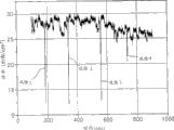
图5的曲线示出了传统的直接液体供应燃料电池的电池堆的功率;Figure 5 is a graph showing the power of a conventional direct liquid fed fuel cell stack;
图6的曲线示出了本发明一实施方式的直接液体供应燃料电池的电池堆的功率;Figure 6 is a graph showing the power of a stack of direct liquid fed fuel cells according to an embodiment of the present invention;
图7是本发明另一实施方式的双极板的透视图。Figure 7 is a perspective view of a bipolar plate according to another embodiment of the present invention.
具体实施方式 Detailed ways
现在将结合附图更全面地对本发明的直接液体供应燃料电池的电池堆进行说明,附图中示出了本发明的一些示例性实施方式。The direct liquid supply fuel cell stack of the present invention will now be described more fully with reference to the accompanying drawings, in which some exemplary embodiments of the invention are shown.
图2是本发明一实施方式的直接液体供应燃料电池的电池堆100的剖面图。直接液体供应燃料电池的电池堆100包括多个垂直堆叠的膜电极组件(MEAs)和设置在这些MEAs之间的导电双极板110。每一MEA包括在薄膜140的任一侧上的阳极142和阴极144。分别接触阳极142和阴极144的导电阳极板161和导电阴极板162位于直接液体供应燃料电池的电池堆100的两外侧上。每一阳极板161和阴极板162的一个表面具有双极板110的形状,它们的作用等同于双极板110。所述MEAS和双极板110、阳极161和阴极162通过螺钉连接固定的端板180a和180b而被固定。FIG. 2 is a cross-sectional view of a
双极板110可以由阳极板161和阴极板162形成。
附图标记150表示诸如垫圈之类的密封部件,其可防止液体燃料从燃料流动孔114a和114b泄露到阴极144。
图3是具有液体燃料流动通道的图2所示的双极板表面的平面图。接触阳极142的阳极板161的表面具有与图3所示的相同形状。在双极板110中,具有蜿蜒形状的多条燃料通道112形成在MEA所处的电极区111上,并且燃料通道112的上部是开放的。还具有与燃料通道112相连的集流管113和燃料流动孔114a和114b,所述燃料流动孔穿过双极板110并与集流管113相连,以便向位于电极区111外侧的区域的燃料电池供给液体燃料和从位于电极区111外侧的区域的燃料电池中排放液体燃料。集流管113使燃料流动孔114a和114b与多条燃料通道112连接。3 is a plan view of the surface of the bipolar plate shown in FIG. 2 with liquid fuel flow channels. The surface of the anode plate 161 contacting the anode 142 has the same shape as shown in FIG. 3 . In the
图4是具有空气流动通道的图2所示的双极板表面的透视图。所述空气流动通道具有多条直流动通道115,这些直流动通道成形为具有矩形剖面的槽。借助于重力及进入的空气流,直流动通道115向下输送由阴极反应产生的水,被输送的水最终形成处于直流动通道115的底部上的水滴。4 is a perspective view of the surface of the bipolar plate shown in FIG. 2 with air flow channels. The air flow channel has a plurality of straight flow channels 115 shaped as grooves with a rectangular cross-section. With the help of gravity and incoming air flow, the straight flow channel 115 transports the water produced by the cathode reaction downwards, the transported water eventually forms water droplets on the bottom of the straight flow channel 115 .
吸收水滴的亲水部件位于双极板110的一侧上。亲水部件170的上表面具有与直流动通道115的底表面相同的平面。因此,亲水部件170的上表面接触并吸收所述水滴。亲水部件170的端部170a连接到其它亲水部件172,而亲水部件172可与水泵P相连。水泵P向外排放由亲水部件172吸收的水。A hydrophilic member that absorbs water droplets is located on one side of the
燃料流动孔114a和114b可以形成在双极板110的突出部分115a处,以形成流动通道115。Fuel flow holes 114 a and 114 b may be formed at the protruding portion 115 a of the
亲水部件170和172可以由如被处理成具有孔的海绵或聚乙烯或聚丙烯之类的多孔材料构成。The hydrophilic members 170 and 172 may be composed of a porous material such as sponge processed to have pores or polyethylene or polypropylene.
根据本发明,由于亲水部件170被形成为没有阻塞空气流动通道,因此其不会使进入的空气产生压力损失。According to the present invention, since the hydrophilic member 170 is formed not to block the air flow passage, it does not cause a pressure loss to the incoming air.
图5的曲线示出了传统的直接液体供应燃料电池的电池堆的功率。Figure 5 is a graph showing the power of a conventional direct liquid fed fuel cell stack.
参考图5,传统的直接液体供应燃料电池的电池堆的功率随时间而降低。其原因可设想为阴极板中的空气流动通道被水阻塞了。吸除1和吸除2表示直接液体供应燃料电池的电池堆的功率通过清除水而被立即恢复。Referring to FIG. 5 , the stack power of a conventional direct liquid supply fuel cell degrades over time. The reason for this is conceivably that the air flow passages in the cathode plate are blocked by water.
图6的曲线示出了本发明一实施方式的直接液体供应燃料电池的电池堆的功率。Figure 6 is a graph showing the power of a stack of direct liquid fed fuel cells according to an embodiment of the present invention.
参考图6,由于在吸除1至吸除4时利用水泵来清除水,所述直接液体供应燃料电池堆的功率维持恒定的高水平。Referring to FIG. 6 , since the water pump is used to remove the water during
图7是本发明另一实施方式的双极板的透视图。图7和图4中相同的附图标记表示相同的部件,因此省略了对它们的描述。Figure 7 is a perspective view of a bipolar plate according to another embodiment of the present invention. The same reference numerals in FIG. 7 and FIG. 4 denote the same components, and thus their descriptions are omitted.
所述空气流动通道由多条直流动通道115形成。借助于重力以及进入的空气流,这些直流动通道115可输送由阴极反应产生的水,而被输送的水最终形成处于直流动通道115的底部上的水滴。The air flow channel is formed by a plurality of straight flow channels 115 . By means of gravity and incoming air flow, these straight flow channels 115 can transport the water produced by the cathode reaction, and the transported water finally forms water droplets on the bottom of the straight flow channels 115 .
吸收水滴的亲水部件270位于双极板110的一侧上。亲水部件270形成双极板110端部的延伸部分。亲水部件270还包括从直流动通道115延伸的槽275,与直流动通道115端部处的槽接触的水滴借助于重力以及进入的空气流被亲水部件270吸收。On one side of the
亲水部件270可以由如被处理成具有孔的海绵或聚乙烯或聚丙烯之类的多孔材料构成。The hydrophilic member 270 may be composed of a porous material such as sponge processed to have pores or polyethylene or polypropylene.
根据本发明,由于亲水部件270被形成为没有阻塞空气流动通道,因此其不会使进入的空气产生压力损失。According to the present invention, since the hydrophilic member 270 is formed not to block the air flow passage, it does not cause a pressure loss to the incoming air.
如上所述,在本发明的直接液体供应燃料电池的电池堆中,接触阴极的导电板的一端与不会阻塞形成在导电板中的空气通道的亲水部件相连。因此,产生在空气通道底部上的水滴容易被亲水部件吸收,并且这不会导致空气流动通道中出现压力损失。As described above, in the stack of the direct liquid supply fuel cell of the present invention, one end of the conductive plate contacting the cathode is connected to a hydrophilic member which does not block the air passage formed in the conductive plate. Therefore, water droplets generated on the bottom of the air passage are easily absorbed by the hydrophilic member, and this does not cause pressure loss in the air flow passage.
虽然通过参考示例性实施方式已具体示出了本发明并对其进行了说明,但是本领域技术人员应认识到,在没有超出权利要求所限定的本发明的构思和范围的前提下,可以对其中的形式和细节进行各种变换。Although the present invention has been specifically shown and described with reference to exemplary embodiments, those skilled in the art will recognize that, without departing from the concept and scope of the present invention defined by the claims, the The forms and details in it undergo various transformations.
Claims (6)
Applications Claiming Priority (2)
| Application Number | Priority Date | Filing Date | Title |
|---|---|---|---|
| KR1020050055114A KR100708693B1 (en) | 2005-06-24 | 2005-06-24 | Direct Liquid Fuel Cell Stack |
| KR55114/05 | 2005-06-24 |
Related Child Applications (1)
| Application Number | Title | Priority Date | Filing Date |
|---|---|---|---|
| CN2008101700477A Division CN101399357B (en) | 2005-06-24 | 2006-04-30 | Direct Liquid Supply Fuel Cell Stacks |
Publications (2)
| Publication Number | Publication Date |
|---|---|
| CN1885608A CN1885608A (en) | 2006-12-27 |
| CN100486021C true CN100486021C (en) | 2009-05-06 |
Family
ID=37567835
Family Applications (2)
| Application Number | Title | Priority Date | Filing Date |
|---|---|---|---|
| CNB2006100771917A Expired - Fee Related CN100486021C (en) | 2005-06-24 | 2006-04-30 | Cell stack for direct liquid feed fuel cell |
| CN2008101700477A Expired - Fee Related CN101399357B (en) | 2005-06-24 | 2006-04-30 | Direct Liquid Supply Fuel Cell Stacks |
Family Applications After (1)
| Application Number | Title | Priority Date | Filing Date |
|---|---|---|---|
| CN2008101700477A Expired - Fee Related CN101399357B (en) | 2005-06-24 | 2006-04-30 | Direct Liquid Supply Fuel Cell Stacks |
Country Status (4)
| Country | Link |
|---|---|
| US (1) | US7488552B2 (en) |
| JP (1) | JP4785617B2 (en) |
| KR (1) | KR100708693B1 (en) |
| CN (2) | CN100486021C (en) |
Families Citing this family (4)
| Publication number | Priority date | Publication date | Assignee | Title |
|---|---|---|---|---|
| KR101156530B1 (en) * | 2005-11-02 | 2012-06-20 | 삼성에스디아이 주식회사 | Direct liquid feed fuel cell |
| US8394547B2 (en) * | 2007-09-07 | 2013-03-12 | GM Global Technology Operations LLC | Fuel cell bipolar plate exit for improved flow distribution and freeze compatibility |
| WO2009078864A1 (en) * | 2007-12-18 | 2009-06-25 | Utc Power Corporation | Fuel cells and methods for reducing blockage of channels of fuel cells |
| US9281536B2 (en) * | 2008-10-01 | 2016-03-08 | GM Global Technology Operations LLC | Material design to enable high mid-temperature performance of a fuel cell with ultrathin electrodes |
Citations (4)
| Publication number | Priority date | Publication date | Assignee | Title |
|---|---|---|---|---|
| US4175165A (en) * | 1977-07-20 | 1979-11-20 | Engelhard Minerals & Chemicals Corporation | Fuel cell system utilizing ion exchange membranes and bipolar plates |
| US5364711A (en) * | 1992-04-01 | 1994-11-15 | Kabushiki Kaisha Toshiba | Fuel cell |
| US20030215686A1 (en) * | 2002-03-04 | 2003-11-20 | Defilippis Michael S. | Method and apparatus for water management of a fuel cell system |
| US20050074652A1 (en) * | 2003-10-01 | 2005-04-07 | Samsung Sdi Co., Ltd. | Direct liquid feed fuel cell stack |
Family Cites Families (10)
| Publication number | Priority date | Publication date | Assignee | Title |
|---|---|---|---|---|
| JPH06188008A (en) * | 1992-04-01 | 1994-07-08 | Toshiba Corp | Fuel battery |
| JPH08138692A (en) * | 1994-11-04 | 1996-05-31 | Toyota Motor Corp | Fuel cell |
| JP2001110432A (en) * | 1999-10-08 | 2001-04-20 | Matsushita Electric Ind Co Ltd | Polymer electrolyte fuel cell |
| NL1014400C1 (en) * | 2000-02-17 | 2001-08-20 | Nedstack Holding B V | Polymer electrolyte fuel cell based heat power generators. |
| US6749892B2 (en) * | 2000-03-22 | 2004-06-15 | Samsung Electronics Co., Ltd. | Method for fabricating membrane-electrode assembly and fuel cell adopting the membrane-electrode assembly |
| US6537351B2 (en) * | 2001-05-29 | 2003-03-25 | Utc Fuel Cells, L.L.C. | Compact light weight condenser assembly |
| JP4281382B2 (en) * | 2002-04-19 | 2009-06-17 | ソニー株式会社 | Generated water treatment system and power generation device |
| JP2005093243A (en) * | 2003-09-17 | 2005-04-07 | Nissan Motor Co Ltd | Fuel cell |
| US7435502B2 (en) * | 2003-09-22 | 2008-10-14 | Utc Power Corporation | Internal PEM fuel cell water management |
| JP2005129431A (en) * | 2003-10-27 | 2005-05-19 | Toyota Motor Corp | Fuel cell and gas separator for fuel cell |
-
2005
- 2005-06-24 KR KR1020050055114A patent/KR100708693B1/en not_active Expired - Fee Related
-
2006
- 2006-04-30 CN CNB2006100771917A patent/CN100486021C/en not_active Expired - Fee Related
- 2006-04-30 CN CN2008101700477A patent/CN101399357B/en not_active Expired - Fee Related
- 2006-05-05 US US11/418,188 patent/US7488552B2/en not_active Expired - Fee Related
- 2006-05-22 JP JP2006141801A patent/JP4785617B2/en not_active Expired - Fee Related
Patent Citations (4)
| Publication number | Priority date | Publication date | Assignee | Title |
|---|---|---|---|---|
| US4175165A (en) * | 1977-07-20 | 1979-11-20 | Engelhard Minerals & Chemicals Corporation | Fuel cell system utilizing ion exchange membranes and bipolar plates |
| US5364711A (en) * | 1992-04-01 | 1994-11-15 | Kabushiki Kaisha Toshiba | Fuel cell |
| US20030215686A1 (en) * | 2002-03-04 | 2003-11-20 | Defilippis Michael S. | Method and apparatus for water management of a fuel cell system |
| US20050074652A1 (en) * | 2003-10-01 | 2005-04-07 | Samsung Sdi Co., Ltd. | Direct liquid feed fuel cell stack |
Also Published As
| Publication number | Publication date |
|---|---|
| US20060292431A1 (en) | 2006-12-28 |
| CN101399357B (en) | 2012-03-28 |
| KR20060135266A (en) | 2006-12-29 |
| JP2007005291A (en) | 2007-01-11 |
| CN101399357A (en) | 2009-04-01 |
| KR100708693B1 (en) | 2007-04-18 |
| JP4785617B2 (en) | 2011-10-05 |
| US7488552B2 (en) | 2009-02-10 |
| CN1885608A (en) | 2006-12-27 |
Similar Documents
| Publication | Publication Date | Title |
|---|---|---|
| JP4527081B2 (en) | Direct liquid fuel cell stack | |
| US8329358B2 (en) | Bipolar plate for fuel cell and fuel cell having the same | |
| US7566511B2 (en) | Solid polymer cell assembly | |
| JP5062392B2 (en) | Polymer electrolyte fuel cell | |
| JP2004079245A (en) | Fuel cell | |
| US7951506B2 (en) | Bipolar plate and direct liquid feed fuel cell stack | |
| CN100486021C (en) | Cell stack for direct liquid feed fuel cell | |
| JP2005251526A (en) | Fuel cell stack | |
| JP2010153175A (en) | Fuel battery | |
| JP4109569B2 (en) | Fuel cell | |
| JP5011749B2 (en) | Fuel cell device | |
| US20040038103A1 (en) | Solid polymer electrolyte fuel cell assembly | |
| US7816049B2 (en) | Direct liquid feed fuel cell | |
| JP2006236612A (en) | Fuel cell | |
| KR100649204B1 (en) | Fuel Cell Systems, Stacks & Separators | |
| KR20030091485A (en) | Fuel supplying method of direct liquid feed fuel cell and fuel cell apparatus adopting the same | |
| US7329472B2 (en) | Fuel cell system and stack used thereto | |
| JP2007234398A (en) | Fuel cell device | |
| KR101122574B1 (en) | Fuel cell system, stack and separator used thereto | |
| KR100550955B1 (en) | Membrane-electrode-gasket assembly for fuel cell with integrated humidification membrane | |
| CN115280558A (en) | Fuel cell unit | |
| JP4809589B2 (en) | Fuel cell | |
| JP2004327091A (en) | Fuel cell stack | |
| KR20060004269A (en) | Humidifier integrated fuel cell separator | |
| JP2009218200A (en) | Fuel cell and fuel cell stack |
Legal Events
| Date | Code | Title | Description |
|---|---|---|---|
| C06 | Publication | ||
| PB01 | Publication | ||
| C10 | Entry into substantive examination | ||
| SE01 | Entry into force of request for substantive examination | ||
| C14 | Grant of patent or utility model | ||
| GR01 | Patent grant | ||
| CF01 | Termination of patent right due to non-payment of annual fee |
Granted publication date: 20090506 Termination date: 20160430 |