CN100483075C - Detector array for optical encoders - Google Patents
Detector array for optical encoders Download PDFInfo
- Publication number
- CN100483075C CN100483075C CNB2005100994605A CN200510099460A CN100483075C CN 100483075 C CN100483075 C CN 100483075C CN B2005100994605 A CNB2005100994605 A CN B2005100994605A CN 200510099460 A CN200510099460 A CN 200510099460A CN 100483075 C CN100483075 C CN 100483075C
- Authority
- CN
- China
- Prior art keywords
- photodiode
- detector array
- scale
- different
- radius
- Prior art date
- Legal status (The legal status is an assumption and is not a legal conclusion. Google has not performed a legal analysis and makes no representation as to the accuracy of the status listed.)
- Active
Links
- 230000003287 optical effect Effects 0.000 title claims abstract description 17
- 238000005259 measurement Methods 0.000 claims description 14
- 238000012797 qualification Methods 0.000 claims description 13
- 238000006073 displacement reaction Methods 0.000 claims description 10
- 230000033001 locomotion Effects 0.000 claims description 5
- 230000000704 physical effect Effects 0.000 claims description 5
- 230000011664 signaling Effects 0.000 claims description 4
- 238000000034 method Methods 0.000 description 16
- 238000001514 detection method Methods 0.000 description 6
- 238000003491 array Methods 0.000 description 5
- 238000010586 diagram Methods 0.000 description 5
- 230000003044 adaptive effect Effects 0.000 description 4
- 230000010363 phase shift Effects 0.000 description 4
- 238000009826 distribution Methods 0.000 description 2
- 238000005457 optimization Methods 0.000 description 2
- VYZAMTAEIAYCRO-UHFFFAOYSA-N Chromium Chemical compound [Cr] VYZAMTAEIAYCRO-UHFFFAOYSA-N 0.000 description 1
- 230000005540 biological transmission Effects 0.000 description 1
- 229910052804 chromium Inorganic materials 0.000 description 1
- 239000011651 chromium Substances 0.000 description 1
- 239000011521 glass Substances 0.000 description 1
- 230000001788 irregular Effects 0.000 description 1
- 238000004519 manufacturing process Methods 0.000 description 1
- 239000000463 material Substances 0.000 description 1
- 230000000737 periodic effect Effects 0.000 description 1
- 229920003023 plastic Polymers 0.000 description 1
- 239000004033 plastic Substances 0.000 description 1
- 238000002310 reflectometry Methods 0.000 description 1
- 239000004065 semiconductor Substances 0.000 description 1
- 238000000926 separation method Methods 0.000 description 1
- 239000000758 substrate Substances 0.000 description 1
- 230000001960 triggered effect Effects 0.000 description 1
Images


Classifications
-
- G—PHYSICS
- G01—MEASURING; TESTING
- G01D—MEASURING NOT SPECIALLY ADAPTED FOR A SPECIFIC VARIABLE; ARRANGEMENTS FOR MEASURING TWO OR MORE VARIABLES NOT COVERED IN A SINGLE OTHER SUBCLASS; TARIFF METERING APPARATUS; MEASURING OR TESTING NOT OTHERWISE PROVIDED FOR
- G01D5/00—Mechanical means for transferring the output of a sensing member; Means for converting the output of a sensing member to another variable where the form or nature of the sensing member does not constrain the means for converting; Transducers not specially adapted for a specific variable
- G01D5/26—Mechanical means for transferring the output of a sensing member; Means for converting the output of a sensing member to another variable where the form or nature of the sensing member does not constrain the means for converting; Transducers not specially adapted for a specific variable characterised by optical transfer means, i.e. using infrared, visible, or ultraviolet light
- G01D5/32—Mechanical means for transferring the output of a sensing member; Means for converting the output of a sensing member to another variable where the form or nature of the sensing member does not constrain the means for converting; Transducers not specially adapted for a specific variable characterised by optical transfer means, i.e. using infrared, visible, or ultraviolet light with attenuation or whole or partial obturation of beams of light
- G01D5/34—Mechanical means for transferring the output of a sensing member; Means for converting the output of a sensing member to another variable where the form or nature of the sensing member does not constrain the means for converting; Transducers not specially adapted for a specific variable characterised by optical transfer means, i.e. using infrared, visible, or ultraviolet light with attenuation or whole or partial obturation of beams of light the beams of light being detected by photocells
- G01D5/347—Mechanical means for transferring the output of a sensing member; Means for converting the output of a sensing member to another variable where the form or nature of the sensing member does not constrain the means for converting; Transducers not specially adapted for a specific variable characterised by optical transfer means, i.e. using infrared, visible, or ultraviolet light with attenuation or whole or partial obturation of beams of light the beams of light being detected by photocells using displacement encoding scales
- G01D5/34707—Scales; Discs, e.g. fixation, fabrication, compensation
- G01D5/34715—Scale reading or illumination devices
-
- G—PHYSICS
- G01—MEASURING; TESTING
- G01D—MEASURING NOT SPECIALLY ADAPTED FOR A SPECIFIC VARIABLE; ARRANGEMENTS FOR MEASURING TWO OR MORE VARIABLES NOT COVERED IN A SINGLE OTHER SUBCLASS; TARIFF METERING APPARATUS; MEASURING OR TESTING NOT OTHERWISE PROVIDED FOR
- G01D5/00—Mechanical means for transferring the output of a sensing member; Means for converting the output of a sensing member to another variable where the form or nature of the sensing member does not constrain the means for converting; Transducers not specially adapted for a specific variable
- G01D5/26—Mechanical means for transferring the output of a sensing member; Means for converting the output of a sensing member to another variable where the form or nature of the sensing member does not constrain the means for converting; Transducers not specially adapted for a specific variable characterised by optical transfer means, i.e. using infrared, visible, or ultraviolet light
- G01D5/32—Mechanical means for transferring the output of a sensing member; Means for converting the output of a sensing member to another variable where the form or nature of the sensing member does not constrain the means for converting; Transducers not specially adapted for a specific variable characterised by optical transfer means, i.e. using infrared, visible, or ultraviolet light with attenuation or whole or partial obturation of beams of light
- G01D5/34—Mechanical means for transferring the output of a sensing member; Means for converting the output of a sensing member to another variable where the form or nature of the sensing member does not constrain the means for converting; Transducers not specially adapted for a specific variable characterised by optical transfer means, i.e. using infrared, visible, or ultraviolet light with attenuation or whole or partial obturation of beams of light the beams of light being detected by photocells
- G01D5/36—Forming the light into pulses
Abstract
A photodiode detector array for optical encoders includes a plurality of photodiodes, each of the photodiodes providing a position signal when the detector array moves relative to the scale. A plurality of switching elements is provided for selectively combining each of the photodiodes with other photo diodes in a defined manner. The switching elements allow the photodiodes to be unambiguously combined for at least two different scale radii so that a defined number of position signals is generated in each case. The combination of the photodiodes differs between the at least two different scale radii.
Description
Technical field
The present invention relates to a kind of detector array that is used for optical encoder.Specifically, the present invention relates to be used for the switchable detector array of different rotary scale radius.
Background technology
Be used for determining that some optical encoder of the relative position between two movable objects is a traditional type.Can determine direction of linear motion and the relative position on the direction of rotatablely moving.In these systems, an object links to each other with the measurement scale usually, and another object then links to each other with scanning element.Under the situation of linear encoder, used the linear scale that has the linear measurement scale, and under the situation of rotary encoder, used to have the circular code-disc of measuring scale.The scanning element that is used for linear movement or rotatablely moves has one or more light sources, and one or more optical detection device.For detecting element, use photodiode usually.
In recent years, it is more and more universal that linear encoder and rotary encoder have become, and they have a plurality of interdigitation photodiodes as detecting element.This detecting device is arranged and is also referred to as phased array or structurized photoelectric detector.Below will use term " detector array ".
These detecting devices are arranged to have traditionally with array way and are arranged on photodiode on the semi-conductor chip.The arrangement of photodiode must be adapted to various scrambler configurations with unique mode.The required geometry arrangement such as its length, width and the spacing that this means photodiode all depend on selected scanning configuration, especially depend on the scale cycle or the scale spacing of scanning survey scale.For some Measurement Resolution that limits by the given scale spacing of measuring scale, have the photodiode that clearly limits and arrange.Therefore, by changing to the resolution that different scanning scale spacings changes scrambler, so also will need to revise the design of photodiode array if desired, so that obtain required scanning configuration or resolution.In this case, need carry out a large amount of design efforts to revise the layout of photodiode array.
In order to address the above problem, the european patent application No.0710819 that has announced has introduced at the some different measuring scales with different scale cycle and has used the detector array that has a plurality of photodiodes.For this reason, have only the photodiode of some to be triggered in all available photodiodes according to scanning scale.All need a kind of adaptive process to determine which photodiode needs trigger for certain scanning scale in all cases.A shortcoming of this system is that it may need complicated ASIC (special IC) to control this adaptive process.Another shortcoming is, the triggering stage of system needs special-purpose tool shelf, and it should allow to make rayed on a plurality of incremental data sets of signals.In addition, need many spaces that are used for storer and interlock circuit on carrier substrates, the aim of the miniaturization as far as possible of this and system is disagreed.
Therefore, U.S. Patent No. 6727493 has been introduced a kind of detector array that can change resolution easily, and it is complete by reference and incorporated herein clearly.For this purpose, the resolution selected cell links to each other with photodiode array, and be used for the resolution of array of controls, wherein all photodiodes relevant with photodiode array are all in running order down, and irrelevant with the selected true resolution of resolution selected cell.Under the situation of whirligig, this arrangement allows switching between different resolution or different code-disc spacing under the rotation scale radius that limits.
Yet, be that wherein the different Another Application of first and second radiuses is necessary if having the scrambler of the rotation scale that is positioned on the code-disc with second radius, U.S. Patent No. 6727493 does not provide solution so.In this case, must be the different photodiode array of each rotation scale radial design once more.This need carry out more design effort to revise the layout of photodiode array, makes it can be used for scanning rotation scale on the code-disc with at least the second rotation scale radius.
If the cue mark of optimizing for the certain scaling radius must be scanned by suitable photodiode detector array, can produce similar problem so.Cue mark on the code-disc is generally used for producing so-called reference signal, and its indication is along the absolute position of a certain qualification of measuring scale.In this case, optimize photodiode detector array, so also need to carry out new design effort if be necessary for different code-disc radiuses.
Summary of the invention
Therefore, an object of the present invention is to provide a kind of detector array that is used for optical encoder, it can use in conjunction with the different scales with different radii.
One exemplary embodiment of the present invention can provide a kind of photodiode detector array that is used for optical encoder, and it can use in conjunction with at least two different scale radiuses.
One exemplary embodiment of the present invention can provide a kind of rotary encoder that has detector array that is used to scan the rotation scale on the code-disc, and wherein photodiode detector array can use in conjunction with at least two different rotation scale radiuses.
One exemplary embodiment of the present invention can provide a kind of photodiode detector array that is used for rotary encoder, and it can be used for scanning the cue mark on the code-disc with different rotary scale radius.
An exemplary enforcement according to the present invention is sharp, and optical encoder can provide the positional information of the scale that can move with respect to detector array, and detector array can be used in conjunction with at least two different scale radiuses.Detector array comprises a plurality of photodiodes, and when detector array moved with respect to scale, each photodiode all provided position signalling.In order optionally each photodiode and other photodiode to be combined in the mode that limits, a plurality of on-off elements are provided.These on-off elements are arranged so that photodiode can combine clearly at least two different scale radiuses, thereby produce position signalling, and photodiode to be combined between these at least two the different scale radiuses be different.
These a plurality of photodiodes can be arranged on two photodiode tracks at least, and each track includes the part photodiode array that photodiode radially extends.Different photodiode tracks can be provided with concentrically with respect to one another.
Part photodiode array in the track can comprise the separated photodiode of physical property in the track, these tracks predetermined circumferential displacement that relatively moved each other.
These different scale radiuses can comprise first limited radius and second limited radius, and wherein first limited radius is different from second limited radius.
These different scale radiuses can comprise first limited radius and the second unlimited radius.
In one exemplary embodiment, each photodiode can be configured to provide the sweep signal that has the qualification phase relation with respect to scale when detector array is moved with respect to scale, like this, by photodiode and on-off element being combined, just can produce the phase-shifted sweep signal that limits quantity at each different scale radius.
Photodiode can be arranged on the different tracks, has the increment sweep signal that same phase concerns with generation, and wherein on-off element is configured to and the photodiode in the different tracks can be coupled together.
A plurality of adjacent photodiodes can be set on each track, thereby produce the increment sweep signal with same phase relation, wherein on-off element is configured to and these a plurality of adjacent photodiodes can be coupled together.
Described at least two photodiode tracks can comprise two tracks that include the part photodiode array, and each track comprises four groups of photodiodes, and it is configured to produce four increment sweep signals that phase relation is 0 °, 90 °, 180 ° and 270 °.
Each organizes the photodiode that photodiode can comprise equal number.
Part photodiode array in the track can comprise the separated photodiode of the physical property that is arranged in track, just different phase relations can be distributed to the photodiode that extends along common radial direction by corresponding switch configuration.
In one exemplary embodiment, detector array is arranged to and can be being moved one section radial displacement in the radial direction with respect to scale, thereby in the required phase relation of in whole array length, setting up all photodiode output signals on the direction of measurement.
Sharp according to an exemplary enforcement, detector array can provide the positional information of the rotatable code-disc of rotation scale with circumferential setting and at least one cue mark.This detector array is suitable for using in conjunction with at least two rotation scales with different radii.Detector array comprises a plurality of photodiodes, and each photodiode is configured to can provide reference signal when detector array is moved with respect to the rotation scale.This array also comprises a plurality of on-off elements, and it is configured to optionally each photodiode and other photodiode be combined in the mode that limits.On-off element is configured to allow to make photodiode to combine clearly at least two different scale radiuses, thereby produce the reference signal of at least one qualification, and this photodiode to be combined between these at least two the different scale radiuses be different.
Each track can comprise two groups of photodiodes, its be configured to produce two each other phase shift 180 ° beacon scanning signal.
In one exemplary embodiment, rotary encoder comprises rotatable code-disc and aforesaid photodiode detector array.
One exemplary embodiment of the present invention can be provided at the simplification of revising the scale radius in the optical encoder, needn't design different photodiode detector arrays.Traditional photodiode detector array can use in conjunction with the scale with different radii.
In addition, feature described here also can be used in conjunction with the detection of indicator signal, and the cue mark that this indicator signal has by scanning on the code-disc of different radii produces.In this case, also can produce the aforesaid similar features relevant with the design cost that can reduce detector array.
Description of drawings
To introduce and show in the accompanying drawings these and other feature and aspect of exemplary embodiment of the present below.
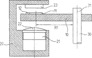
Fig. 1 has schematically shown the side view of optical rotary coder.
Fig. 2 has schematically shown the exemplary embodiment of photodiode detector array, and two part figure with rotation scale of different radii.
Fig. 3 a has shown that schematically the exemplary embodiment of photodiode detector array shown in Figure 2 is applied to have first situation of rotating in the scale of first radius.
Fig. 3 b has shown that schematically the exemplary embodiment of photodiode detector array shown in Figure 2 is applied to have second situation of rotating in the scale of second radius.
Fig. 3 c is the partial enlarged drawing of detector array shown in Fig. 3 b.
Fig. 4 a is the details drawing of detector array shown in Fig. 3 a.
Fig. 4 b has shown detector array shown in Fig. 4 a that is applicable to the first rotation scale with first radius.
Fig. 4 c has shown detector array shown in Fig. 4 b that is applicable to the second rotation scale with second radius.
Fig. 5 has shown the process flow diagram that is used to be interpreted as a certain rotation scale radius and optimizes the illustrative methods of photodiode detector array.
Fig. 6 has shown a part of scale and a part of photodiode array on the code-disc.
Fig. 7 has schematically shown another possibility that the gained mismatch of the photodiode at the place, perimeter of detector array is proofreaied and correct.
Fig. 8 has schematically shown exemplary embodiment and two scale cue marks that are used for different rotary scale radius of photodiode detector array.
Fig. 9 a has shown that schematically the exemplary embodiment of photodiode detector array shown in Figure 8 is applied to the situation in first cue mark at radius R 1 place.
Fig. 9 b has shown that schematically the exemplary embodiment of photodiode detector array shown in Figure 8 is applied to the situation in second cue mark at radius R 2 places.
Embodiment
Fig. 1 has schematically shown the sectional view of optical rotary coder according to an illustrative embodiment of the invention.This rotary encoder can produce the positional information relevant with the motion of two rotating objects.For example, it can be used in the application of lathe and motor.
The optical encoder of this exemplary embodiment comprises the code-disc 10 that has increment rotation scale 11.Rotation scale 11 is made up of the track that has along the opaque and transparent rectangular area that direction of measurement is arranged alternately.Rotation scale 11 circumferentially is arranged on the code-disc 10 symmetrically around rotation, and has qualification radius R 1 as shown in Figure 1.Code-disc 10 is made by glass or plastics, and the zone of opacity of rotation scale 11 is made by the chromium that is deposited on the backing material.Code-disc 10 is installed on the axle 30, and axle 30 for example can link to each other with the rotor of brushless formula motor.
In addition, rotary encoder has scanning element 20, and it comprises light source 21, collimation lens 22 and detector array 23.In exemplary embodiment shown in Figure 1, rotation scale 11 is set in place between the light source 21 and collimation lens 22 and the detector array 23 at opposite side of a side.The light that light source 21 is sent is through lens 22 alignments, and transmission sees through the rotation scale 11 on the code-disc 10.The detector array that is arranged on the detection plane receives transmitted light, if rotation scale 11 is rotated around axis 31, then this transmitted light is through 11 modulation of rotation scale.In one exemplary embodiment, on detection plane, produced the interference pattern that the rotation that depends on code-disc circulates and modulates.Detector array 23 scans the interference pattern after this modulation in a conventional manner, to produce sweep signal S0, S90, S180, S270.In being arranged on the control module in downstream, further handle these modulated luminance signal S0, S90, S180, S270s relevant with the position.
Except the track of band rotation scale 11, be provided with cue mark 12 in another track on the code-disc 10 of the qualification position that is close to increment rotation scale 11.Cue mark 12 is used for producing so-called reference signal at the place, the absolute position that clearly limits along measuring route, and like this, the absolute position that the increment measurement that is undertaken by scanning increment rotation scale can be certain is as benchmark.In some alternative exemplary embodiments, also a plurality of cue marks can be set on code-disc, or the like.
Though the rotation scale 11 of the example of this transmitted light formula scrambler comprises the increment pattern that is arranged alternately the transparent and zone of opacity on code-disc 10 along direction of measurement, but in the exemplary embodiment of incident light formula scrambler, the rotation scale also can be made up of the graded area of high reflectance and antiradar reflectivity.
The structure that in Fig. 1, has just schematically shown scrambler, this be because the details of its mechanical realization to be considered to those of ordinary skill in the art known.
The detector array 23 of the scanning element 20 of rotary encoder shown in Figure 1 can be used with the scale with different radii.In order to scan for example different rotation scales, do not need to design brand-new detector array hardware.Identical detector array hardware can use under different configuration statuses, so that at least two scales of scanning different radii.Based on this dirigibility, can reduce the design effort that must have originally significantly.
In Fig. 2, schematically shown this principle, shown an exemplary embodiment of photodiode detector array 123 among the figure, and had different radii R1, the partial views of two rotation scales 111.1,111.2 of R2 (R1〉R2).In the exemplary embodiment of transmitted light formula scrambler, rotation scale 111.1 and 111.2 is made up of the track of the zone that has the different optical attribute that is arranged alternately such as transparent region and zone of opacity.Detector array 123 and rotation scale 111.1 or 111.2 can be moved each other along direction of measurement x.Same photodiode detector array 123 can be used for scanning first increment rotation scale 111.1 with first radius R 1, and scanning has second increment rotation scale 111.2 of second radius R 2.Be schematically shown as Fig. 2, radius R 1 is different with R2.
As shown in Figure 2, photodetector array 123 comprises a plurality of rectangular photodiode 124 as photoelectric detection system that are positioned at detection plane.Photodiode 124 is arranged at least one partial arc adjacent to each other along direction of measurement x.Direction of measurement x is corresponding to the direction that rotatablely moves of rotation scale 111.1,111.2.In one exemplary embodiment, photodetector array 123 comprises 120 independent photodiodes 124, and these photodiodes 124 have length l=400 μ m and width b=60 μ m.
If in the rotary encoder of Fig. 1, make detector array 123 with respect to rotation scale 111.1 or 111.2 motions, each photodiode 124 of photodetector array 123 just provides periodic sweep signal S0, S90, S180, S270, and it has the phase relation of qualification with respect to the rotation scale 111.1,111.2 that is scanned.Those generations have sweep signal S0, the S90 of same phase relation, the photodiode 124 of S180, S270 is electrically connected mutually, and has formed one group of photodiode that the sweep signal of qualification phase can be provided.In one exemplary embodiment, sweep signal S0, S90, S180, the S270 that is produced by photodiode 124 is sine-shaped.The sweep signal S0 of each out of phase, S90, S180, S270 are produced by the single photodiode 124 of some, and they can suitably connect or switch to together by on-off element.Can produce sweep signal S0, S90, S180, the S270 of four quadratures, their phase place has moved the phase mass that limits each other.Sweep signal S90, S180, S270 with respect to signal S0 phase shift 90 °, 180 ° and 270 °.The sweep signal S0 of quadrature, S90, S180, S270 can handle in a conventional manner by the assessment unit that is arranged on the downstream, thereby can obtain two increment output signal A, B that for example are used to control purpose, this output signal A, B have 90 ° phase shift each other.
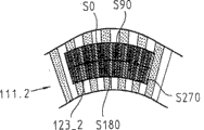
Fig. 3 a and 3b have shown that schematically the detector array of Fig. 2 is applied to have the situation in the different rotary scale 111.1,111.2 of radius R 1 and R2.Because different switching state or configuration statuses, in Fig. 3 a and 3b, indicate detector array with different label 123_1,123_2.In Fig. 3 a and 3b, the different hacures of the photodiode among detector array 123_1, the 123_2 are represented the out of phase relation of the photodiode in the detector array.In both cases, shown four kinds of dissimilar hacures, its expression has by scanning different sweep signal S0, S90, S180 and the S270 of four phase places that corresponding rotation scale 111.1 or 111.2 produces.
As can be seen, for two different radius Rs 1, R2, in detector array, exist two kinds different photodiode is connected and switch to together clear and definite mode in detector array 123_1 from Fig. 3 a and 3b and the comparison of 123_2.In 4c, explain the mode that realizes the different switching states of array 123_1 and 123_2 by suitable on-off element that also schematically shown at Fig. 4 a.
Shown in Fig. 2,3a and 3b, the detector array that is used for this example comprises two photodiode tracks adjacent and that be provided with concentrically with respect to one another.Each photodiode track is included in the part photodiode array of rectangle (or more accurately for trapezoidal) photodiode that extends in the radial direction.This part photodiode array is included in the separated photodiode of physical property in two tracks that can suitably be connected with each other.In detector array, also can be provided with by this way and surpass two tracks.
Providing the photodiode track of two or many concentric arrangement can reduce the situation that the signal that is produced by the exterior light electric diode in the detector array has wrong signal phase relation takes place.By realizing this arrangement, can distribute for each photodiode in each track with respect to the scale structure that is scanned is the phase relation of required (or correct), thereby can avoid the potential phase error of the exterior light electric diode in the array.Otherwise for example the exterior light electric diode may be because it possess correct phase relation in the radial direction extended length.
About on different tracks, provide two part photodiode arrays with and specific geometry arrangement, have several different exemplary embodiment that can realize.
Different part photodiode tracks can be set, and it has relatively moved the displacement that limits each other, thereby can avoid the phase error of some photodiode.At this on the one hand, whole part photodiode array can be movable relative to each other, and optionally only some photodiode in the part photodiode array be moved required displacement.
No circumferential displacement also is fine between the photodiode in each track, but different phase relations is distributed to the photodiode that extends along same radial direction by suitable switch configuration this moment.This can provide more simple manufacturing process.
Fig. 3 c is suitable in radius R 2 times work and according to the zoomed-in view of the left perimeter of the detector array arrangement 111.2 of this principle design.In Fig. 3 c, indicated the photodiode that the unlike signal phase place is provided with different hacures.In Fig. 3 c, for example shown that for photodiode 124 (180) _ A among the inner part photodiode array 123_2A distribute 180 ° of phase relations be the mode that photodiode 124 (0) _ B of the radially adjoining among the outside part photodiode array 123_2B distribute 0 ° of phase relation.
Under these two kinds of configuration statuses, with providing in the detector array photodiode of signal of same phase relation be electrically connected.
As using the equality detector array rotation scale radius R 1 different, the basic demand of R2, need detector array to comprise a plurality of on-off elements with at least two.On-off element is used for making up single photodiode in the mode that clearly limits at each scanning scale radius, thereby guarantees to produce under these at least two kinds of situations output signal S0, S90, S180, the S270 with required phase relation.The mode of combination photoelectric diode is different in both cases.
Need not distribute based on the light that a certain coding structure produced makes photodiode array adapt to the dynamic self-adapting process of a certain scale structure.Comparatively speaking, can determine as described below to be suitable for scanning that to have the geometric configuration of qualification be the array configurations state of the scale of relevant radii, be this configuration status of selected constant radius then.The adaptive process that does not need other.
Fig. 4 a is as in conjunction with the described detector array 123 of Fig. 2 and a plurality of on-off element 125.1 to 125.7 be used for the partial schematic diagram of four signal wires 126.1 to 126.4 of four different scanning signal S0, S90, S180, S270, and wherein these sweep signals are different with respect to the phase relation of the scale structure that is scanned.For clarity, the synoptic diagram among Fig. 4 a to 4c has only shown in two part photodiode arrays among Fig. 3 a, the 3b one.7 photodiodes shown in label 124.1 to the 124.7 expression detector arrays 123, detector array 123 comprises that the typical case of 120 independent photodiodes uses.Each photodiode 124.1 to 124.7 all links to each other with on-off element 125.1 to 125.7.On-off element 125.1 to 125.7 comprises two independent switches 1,2, and it allows at least one in corresponding photodiode 124.1 to 124.7 and four signal wires 126.1 to 126.4 is linked to each other.Have the scale of radius R 1 or radius R 2 if utilize photodiode array to scan, then must trigger switch 1 or switch 2 in the different on-off elements 125.1 to 125.7.If scan more (as N) different radius, each on-off element must have more (as N) switch.Come trigger switch element 125.1 to 125.7 and switch 1,2 thereof by the mode that suitable control line can limit.Correct connection between single photodiode 124.1 to 124.7 and the appropriate signal wire 126.1 to 126.4 selects to depend on the scale radius that is scanned by detector array 123.
In order to show this principle, Fig. 4 b has shown two kinds of different modes with 4c, wherein the photodiode 124.1 to 124.7 of detector array 123 shown in Fig. 4 a links to each other with signal wire 126.1 to 126.4, to produce the sweep signal S0 to S270 of four phase shifts under different scale radius Rs 1, the R2.Two kinds of different configuration 123_1,123_2 of detector array have caused this two exemplary embodiments.In addition, a part that is scanned scale structure 111.1,111.2 that in Fig. 4 b and 4c, has also shown different radii with transparent and zone of opacity.
Therefore, the detector array part 123_1 as shown in Fig. 4 b is suitable for scanning the first rotation scale with first radius R 1, and the detector array part 123_2 as shown in Fig. 4 c is suitable for scanning the second rotation scale with second radius R 2.For this reason, be necessary for different photodiode 124.1 to 124.7 and distribute in 0 ° in four unlike signal phase places, 90 °, 180 °, 270 ° or the signal wire 126.1 to 126.4 one respectively.
Illustrate to be that different photodiodes 124.1 to 124.7 distributes 0 °, 90 °, 180 °, 270 ° different of the signal phases or the mode of signal wire 126.1 to 126.4 in both cases below with reference to Fig. 5.
Shown in Fig. 4 b and 4c,, caused the different distributions of the different photodiode of phase place 124.1 to 124.7 in both cases because of selected on off state difference.In Fig. 4 b, the photodiode 124.1 to 124.7 in the detector array of optimizing for sweep radius R1 has been assigned with 0 ° of signal phase, 90 °, 90 °, 180 °, 270 °, 0 °, 0 °.Comparatively speaking, the photodiode 124.1 to 124.7 in the detector array of optimizing for sweep radius R2 has been assigned with 0 ° of signal phase, 90 °, 180 °, 270 °, 0 °, 90 °, 180 °.These two kinds of array configurations can be provided for producing the appropriate signals quality of the different sweep signal S0 to S270 of four required phase places.
Describe a kind of method below in conjunction with the synoptic diagram of process flow diagram shown in Figure 5 and Fig. 6, wherein can come for optimizing the given suitable photodiode detector array that is used for producing four orthogonal increment sweep signals at least one of in two in the optical rotary coder different scale radiuses by trigger switch element suitably.
In step S10, start after the optimizing process, in step S20, must qualification can in required application, be used as the code-disc pattern that rotates scale.This means the radius R that to select the rotation scale on the code-disc.In addition, step S20 requires to select the spacing P of increment rotation scale.The spacing P of the increment scale that is scanned is defined as the pattern length of opaque and transparent part of the adjacent setting of scale shown in Figure 6.Step S20 also requires to limit the radially expanded range of scale structure, and limits the geometry in particular of the opaque and transparent part of scale.
After the geometric data of having selected the rotation scale, following step S30 to S70 relates to the optimization of photodiode detector array, and photodiode or its part and the suitable location of different on-off elements or interconnection separately.
In step S30, determine that different photodiodes in the detector array are with respect to the phase position of rotation scale structure.Consult Fig. 6 in conjunction with this step and later step, it has shown a part of scale structure 211 and a part of photodiode detector array 223, and it has several photodiodes D1 to D10 of this detector array 223.In addition, in Fig. 6, schematically shown phase relation between photodiode D1 to D10 and the scale 211.
Step S30 at first requires to be defined for the center phase value of the photodiode of generation signal S0, S90, S180, S270 with respect to the scale structure.In example shown in Figure 6, the center phase value that has produced the photodiode D1 of signal S0 is chosen as 40 °, the center phase value that has produced the photodiode D2 of signal S90 is chosen as 115 °, the center phase value that has produced the photodiode D3 of signal S180 is chosen as 180 °, the center phase value that has produced the photodiode D4 of signal S270 is chosen as 250 °.
In the next step S40 of optimizing process, check by formula (1a), (1b) expressed condition whether be similar to the arrangement that has realized the different photodiodes in the detector array at least:


Wherein, Dn represent photodiode Dn (n=1,2,3...) with respect to the phase relation of scale structure,

These conditions can exemplarily be understood as and require the average phase of identical each signal that photodiode produced of all phase places should be approximately equal to the center phase value.
If satisfy formula (1a) and (1b) expressed condition at least approx, and suitably selected the phase position of photodiode, optimizing process can advance to step S50 so.Otherwise, will exchange photodiode at its phase position according to step S45, until satisfy formula (1a) at least approx and (1b) time till.By triggering different switch configurations, can realize the exchange of the photodiode in the optimizing process.
In step S50, the quantity of the photodiode of each independent phase place is further checked.At this on the one hand, attempt to make the quantity of the photodiode that has produced signal to equate with out of phase relation.This requirement can be expressed by following relation (2):
N (0 °) ≈ N (90 °) ≈ N (180 °) ≈ N (270 °) formulas (2)
Wherein, N (0 °) expression produces the quantity of the photodiode of 0 ° of signal, N (90 °) expression produces the quantity of the photodiode of 90 ° of signals, N (180 °) expression produces the quantity of the photodiode of 180 ° of signals, and N (270 °) expression produces the quantity of the photodiode of 270 ° of signals.
If select to be used for the quantity of the photodiode of unlike signal phase place according to this requirement, can guarantee that so all increment sweep signals that detector array produces all have roughly the same signal amplitude and signal bias amount.This is very important for further handle these signals in follow-up interpolation algorithm formula electronic equipment.
If relation (2) also satisfies, just finish this optimizing process at step S70 place so.Otherwise just will exchange different photodiodes according to step S60, until approximate at least satisfied this condition till.
By optionally making up these different photodiodes, just can in step S45 and S60, realize the suitable exchange of the photodiode in the detector array by suitable on-off element.Because given hardware configuration can only satisfy the above-mentioned requirements among formula (1a), (1b) and (2) approx.Yet the scale that has different scale radiuses for scanning also can be used identical detector array, and obtains enough signal qualitys.
Each scale radius at least two that are used for detector array different scale radiuses can be carried out this optimizing process.As the result of this process, can obtain to be used for the detector array of the suitable configurations of different scale radiuses.
About possible scale radius, the detector array of process said process optimization can have at least two different limited radius values.Yet in two radius values one is a finite value and another radius value is under the situation of infinitary value, also can use identical detector array.This means for rotary encoder and linear encoder, can use identical detector array hardware.
In the example of detector array shown in Figure 2, certain phase mismatch problem at place, array perimeter can and provide at least two photodiode tracks to solve by separation arrays as described above in the radial direction.In Fig. 7, shown another solution of handling this problem.
Fig. 7 has shown can be by the part of the rotation scale 311 with radius R 1 of detector array 322 scannings.For the exterior light electric diode that guarantees detector array 322 can produce the sweep signal that has required phase relation with respect to rotation scale 311, this array can be set in scanning element make it move radially certain displacement Δ R1.At this on the one hand, Δ R1 has described from the displacement of the detector array that calculates the relative position of the detector array 322 of complete overlapping part and rotation scale 311.
This measurement can guarantee that the required phase relation of all photodiode output signals all is based upon on the whole array length on the direction of measurement x at least approx.If scanning has the second rotation scale of radius R 2, this adaptive detector array 322 must be arranged to make it to move radially displacement Δ R2.
Above-mentioned principle also can be applicable to by producing reference signal with the suitable cue mark of suitable detector array column scan.To schematically make an explanation with reference to Fig. 8 to 10 to this.
Fig. 8 has schematically shown the exemplary embodiment of photodiode detector array and two scale cue marks, it is used for the different rotary scale radius of similar situation shown in Figure 2, and it has described the scanning to two increment rotation scales with different radii.In Fig. 8, omitted the track that has increment rotation scale.
Detector array 223 shown in Figure 8 can be used for scanning first cue mark 211.1 and second cue mark 211.2.First cue mark 211.1 and second cue mark 211.2 can be arranged on the code-disc with different radii in a conventional manner and be adjacent to increment rotation scale track.First cue mark 211.1 can the rotation scale 111.1 in Fig. 2 use, and second cue mark 211.2 can the rotation scale 111.2 in Fig. 2 use.As shown in Figure 8, these two cue marks are applicable to certain radius R 1 or R2 and are optimized for it.
Cue mark 211.1,211.2 comprises the irregular distribution that is positioned at the zone with different optical attribute on the code-disc.In aforesaid transmitted light formula scrambler, the zone of cue mark is opaque and transparent.
Similar with above-mentioned situation, can be used for scanning the cue mark that is suitable for different radii along direction of measurement x with respect to the detector array 223 that cue mark 211.1 or 211.2 moves, thereby produce the reference signal of one or more qualifications.This may be owing to the dirigibility of the different photodiodes switchings of array and suitable on-off element, and makes it be suitable for the geometric configuration of the cue mark of certain qualification.
The suitable on off state and the different cue mark that in Fig. 9 a and 9b, have schematically shown the detector array 223_1 under the different radii, 223_2.As shown in the figure, the mode that photodiode switches to together is different for two radiuses, and depends on selected cue mark structure.
Therefore, foregoing also can be used for scanning the cue mark under the different radii.If this array uses with the cue mark of optimizing for different radii, so just do not need to carry out the extra design effort relevant with detector array hardware.
Claims (15)
1. detector array that is used for optical encoder, it can provide can be with respect to the positional information of the scale of described detector array motion, described detector array is suitable for using in conjunction with at least two scales with different radii, and described detector array comprises:
A plurality of photodiodes, each photodiode are configured to position signalling can be provided when described detector array is moved with respect to described scale; With
A plurality of on-off elements, it is configured in the mode that limits each photodiode and other photodiode optionally be combined;
Wherein, described on-off element is configured to allow at least two different scale radiuses and described photodiode is combined clearly producing position signalling, described photodiode to be combined between described at least two different scale radiuses be different.
2. detector array according to claim 1, it is characterized in that, described a plurality of photodiode is arranged in two photodiode tracks at least, each described track comprises photodiode at the part photodiode array that extends in the radial direction, and these different photodiode tracks are arranged to concentrically with respect to one another.
3. detector array according to claim 2, it is characterized in that, part photodiode array in the described track comprises the separated photodiode of the physical property that is arranged in described track, the described track predetermined circumferential displacement that relatively moved each other.
4. detector array according to claim 1 is characterized in that, described different scale radius comprises first limited radius and second limited radius, and described first limited radius is different from described second limited radius.
5. detector array according to claim 1 is characterized in that, described different scale radius comprises first limited radius and the second unlimited radius.
6. detector array according to claim 2, it is characterized in that, each described photodiode is configured to provide the sweep signal that has the qualification phase relation with respect to described scale when described detector array is moved with respect to described scale, like this, combine by the photodiode and the on-off element that will be used for each different scale radiuses, just can produce the phase-shifted sweep signal that limits quantity.
7. detector array according to claim 6, it is characterized in that, photodiode in the different tracks is arranged to produce the increment sweep signal with same phase relation, and described on-off element is configured to and the photodiode in the different tracks can be coupled together.
8. detector array according to claim 6, it is characterized in that, a plurality of adjacent photodiode in each track is arranged to produce the increment sweep signal with same phase relation, and described on-off element is configured to and described a plurality of adjacent photodiode can be coupled together.
9. detector array according to claim 6, it is characterized in that, described at least two photodiode tracks comprise two tracks that include the part photodiode array, each described track comprises four groups of photodiodes, and it is configured to produce four increment sweep signals that phase relation is 0 °, 90 °, 180 ° and 270 °.
10. detector array according to claim 9 is characterized in that each organizes the photodiode that photodiode comprises equal number.
11. detector array according to claim 6, it is characterized in that, part photodiode array in the described track comprises the separated photodiode of the physical property that is arranged in track, just different phase relations can be distributed to the photodiode that extends along same radial direction by corresponding switch configuration.
12. detector array according to claim 6, it is characterized in that, described detector array can move one section radial displacement in the radial direction with respect to described scale, thereby sets up the required phase relation of all photodiode output signals in the whole array length on direction of measurement.
13. detector array, be used to provide the positional information of the rotatable code-disc of rotation scale with circumferential setting and at least one cue mark, described detector array is suitable for using in conjunction with at least two rotation scales with different radii, and described detector array comprises:
A plurality of photodiodes, each described photodiode are configured to provide reference signal when described detector array is moved with respect to described rotation scale; With
A plurality of on-off elements, it is configured in the mode that limits each photodiode and other photodiode optionally be combined;
Wherein, described on-off element is configured to allow to make described photodiode to combine clearly at least two different rotation scale radiuses, thereby produce the reference signal of at least one qualification, and described photodiode to be combined between described at least two different scale radiuses be different.
14. detector array according to claim 13 is characterized in that, each described track comprises two groups of photodiodes, and it is configured to produce the beacon scanning signal that two phase places have moved 180 ° each other.
15. a rotary encoder, it comprises rotatable code-disc and according at least one the described photodiode detector array among the claim 1-14.
Applications Claiming Priority (2)
| Application Number | Priority Date | Filing Date | Title |
|---|---|---|---|
| US10/927990 | 2004-08-26 | ||
| US10/927,990 US7199354B2 (en) | 2004-08-26 | 2004-08-26 | Detector array for optical encoders |
Publications (2)
| Publication Number | Publication Date |
|---|---|
| CN1740753A CN1740753A (en) | 2006-03-01 |
| CN100483075C true CN100483075C (en) | 2009-04-29 |
Family
ID=35478730
Family Applications (1)
| Application Number | Title | Priority Date | Filing Date |
|---|---|---|---|
| CNB2005100994605A Active CN100483075C (en) | 2004-08-26 | 2005-08-26 | Detector array for optical encoders |
Country Status (6)
| Country | Link |
|---|---|
| US (1) | US7199354B2 (en) |
| EP (1) | EP1630528B1 (en) |
| JP (1) | JP5030404B2 (en) |
| CN (1) | CN100483075C (en) |
| AT (1) | ATE470132T1 (en) |
| DE (1) | DE602005021584D1 (en) |
Families Citing this family (15)
| Publication number | Priority date | Publication date | Assignee | Title |
|---|---|---|---|---|
| JP2008537358A (en) * | 2005-04-19 | 2008-09-11 | ブーカム テクノロジー ピーエルシー | Electronic wavelength marker system and method |
| JP2007064755A (en) * | 2005-08-30 | 2007-03-15 | Samutaku Kk | Signal processing circuit for encoder |
| DE102007050253A1 (en) * | 2007-10-20 | 2009-04-23 | Dr. Johannes Heidenhain Gmbh | Detector element array for an optical position-measuring device |
| US8493572B2 (en) | 2010-05-05 | 2013-07-23 | Mitutoyo Corporation | Optical encoder having contamination and defect resistant signal processing |
| JP2012053023A (en) * | 2010-09-03 | 2012-03-15 | Olympus Corp | Encoder |
| JP5765968B2 (en) * | 2011-02-28 | 2015-08-19 | キヤノン株式会社 | Optical encoder |
| DE102011075286A1 (en) * | 2011-05-05 | 2012-11-08 | Dr. Johannes Heidenhain Gmbh | Optical position measuring device |
| CN103712643B (en) * | 2013-12-26 | 2015-12-16 | 南京埃斯顿自动化股份有限公司 | A kind of encoder verification mechanism |
| US11061338B2 (en) * | 2014-04-17 | 2021-07-13 | Nikon Corporation | High-resolution position encoder with image sensor and encoded target pattern |
| US11262376B2 (en) * | 2016-06-02 | 2022-03-01 | Weifang Goertek Microelectronics Co., Ltd. | MEMS device and electronic apparatus |
| US10551223B2 (en) * | 2017-03-20 | 2020-02-04 | Tt Electronics Plc | Method and apparatus for configurable photodetector array patterning for optical encoders |
| CN107063432B (en) * | 2017-04-07 | 2019-07-12 | 华南师范大学 | Optical means and device a kind of while that measure ultrasonic wave direction, the sound intensity and frequency |
| US11378422B2 (en) | 2018-11-05 | 2022-07-05 | Tt Electronics Plc | Method and apparatus for improved performance in encoder systems by configuring a detector array using a partition map and assigning weights to output currents of the detector array |
| TWI680648B (en) * | 2018-12-26 | 2019-12-21 | 財團法人工業技術研究院 | Code disk, optical detector, optical absolute rotary encoder and method for outputting, error detecting and correcting code values |
| DE102020118639B3 (en) * | 2020-07-15 | 2021-01-07 | Sick Stegmann Gmbh | Code elements of a measuring standard of an encoder device |
Family Cites Families (11)
| Publication number | Priority date | Publication date | Assignee | Title |
|---|---|---|---|---|
| US4259570A (en) * | 1978-11-27 | 1981-03-31 | Hewlett-Packard Company | Optical comparator |
| US4786891A (en) * | 1986-04-08 | 1988-11-22 | Yokogawa Electric Corporation | Absolute encoder for linear or angular position measurements |
| DE3737278A1 (en) * | 1986-11-04 | 1988-05-11 | Canon Kk | METHOD AND DEVICE FOR OPTICALLY DETECTING THE POSITION OF AN OBJECT |
| JP2794798B2 (en) * | 1989-06-30 | 1998-09-10 | 株式会社安川電機 | Encoder |
| US5438330A (en) * | 1991-10-28 | 1995-08-01 | Nikon Corporation | Absolute encoder |
| DE4439693C2 (en) | 1994-11-05 | 1997-04-24 | Hengstler Gmbh | Sensor unit for a rotary encoder or linear encoder |
| US5698851A (en) * | 1996-04-03 | 1997-12-16 | Placa Ltd. | Device and method for precise angular measurement by mapping small rotations into large phase shifts |
| FR2757628B1 (en) * | 1996-12-20 | 1999-02-26 | Eaton Controls | METHOD AND DEVICE FOR DIGITAL MEASUREMENT OF ANGULAR POSITIONS |
| US6727493B2 (en) * | 2001-11-06 | 2004-04-27 | Renco Incoders, Inc. | Multiple resolution photodiode sensor array for an optical encoder |
| JP2003240607A (en) * | 2002-02-18 | 2003-08-27 | Canon Inc | Electric dividing network of encoder |
| JP2005017116A (en) * | 2003-06-26 | 2005-01-20 | Sharp Corp | Photo detector for optical encoder |
-
2004
- 2004-08-26 US US10/927,990 patent/US7199354B2/en not_active Expired - Fee Related
-
2005
- 2005-07-22 DE DE602005021584T patent/DE602005021584D1/en active Active
- 2005-07-22 AT AT05015944T patent/ATE470132T1/en not_active IP Right Cessation
- 2005-07-22 EP EP05015944A patent/EP1630528B1/en active Active
- 2005-08-25 JP JP2005243704A patent/JP5030404B2/en not_active Expired - Fee Related
- 2005-08-26 CN CNB2005100994605A patent/CN100483075C/en active Active
Also Published As
| Publication number | Publication date |
|---|---|
| EP1630528A2 (en) | 2006-03-01 |
| EP1630528A3 (en) | 2009-08-05 |
| ATE470132T1 (en) | 2010-06-15 |
| CN1740753A (en) | 2006-03-01 |
| US20060043272A1 (en) | 2006-03-02 |
| EP1630528B1 (en) | 2010-06-02 |
| JP5030404B2 (en) | 2012-09-19 |
| US7199354B2 (en) | 2007-04-03 |
| JP2006064702A (en) | 2006-03-09 |
| DE602005021584D1 (en) | 2010-07-15 |
Similar Documents
| Publication | Publication Date | Title |
|---|---|---|
| CN100483075C (en) | Detector array for optical encoders | |
| US7770304B2 (en) | Position-measuring device and method for determining absolute position | |
| US7164120B2 (en) | Position measuring instrument | |
| EP0100243B1 (en) | Position sensor | |
| US5241172A (en) | Variable pitch position encoder | |
| US7301142B2 (en) | Optical encoder photodetector array with multiple resolutions | |
| US7013575B2 (en) | Position measuring device | |
| CN100514004C (en) | Rotary emitter and method for scanning the code disk of a rotary emmitter | |
| US20070186431A1 (en) | Position measuring arrangement | |
| US6727493B2 (en) | Multiple resolution photodiode sensor array for an optical encoder | |
| EP1010967B1 (en) | Encoder for providing incremental and absolute position data | |
| JP2011133286A (en) | Rotary encoder | |
| JPH01240820A (en) | Positional information generator and code arrangement body for said generator | |
| US9810554B2 (en) | Position measuring instrument | |
| CN111366178A (en) | Code disc, light detector, encoder and code value output, error detection and error correction method | |
| US5274229A (en) | Absolute position encoder | |
| US9933284B2 (en) | Multi-track absolute encoder | |
| JP4425220B2 (en) | Absolute encoder | |
| US5574559A (en) | Displacement detection apparatus using multiple displacement detection signals formed by a multiple phase combination grating | |
| JP2007071732A (en) | Absolute value encoder of optical type | |
| JP2001208567A (en) | Optical encoder for quantitative detection of linear motion or rotational motion | |
| US20050088667A1 (en) | Absolute position encoder requiring less than one encoding track per bit | |
| US4970387A (en) | Position transducer having absolute position compensation | |
| US7123354B2 (en) | Optical position measuring device | |
| US7196319B2 (en) | Position-measuring device |
Legal Events
| Date | Code | Title | Description |
|---|---|---|---|
| C06 | Publication | ||
| PB01 | Publication | ||
| C10 | Entry into substantive examination | ||
| SE01 | Entry into force of request for substantive examination | ||
| C14 | Grant of patent or utility model | ||
| GR01 | Patent grant |