CN100480503C - Internal combustion engine , cylinder head and fabricating method and gas supply system - Google Patents
Internal combustion engine , cylinder head and fabricating method and gas supply system Download PDFInfo
- Publication number
- CN100480503C CN100480503C CNB2004100758699A CN200410075869A CN100480503C CN 100480503 C CN100480503 C CN 100480503C CN B2004100758699 A CNB2004100758699 A CN B2004100758699A CN 200410075869 A CN200410075869 A CN 200410075869A CN 100480503 C CN100480503 C CN 100480503C
- Authority
- CN
- China
- Prior art keywords
- suction tude
- wall
- cylinder head
- projection
- distributor
- Prior art date
- Legal status (The legal status is an assumption and is not a legal conclusion. Google has not performed a legal analysis and makes no representation as to the accuracy of the status listed.)
- Expired - Lifetime
Links
Images


Classifications
-
- F—MECHANICAL ENGINEERING; LIGHTING; HEATING; WEAPONS; BLASTING
- F02—COMBUSTION ENGINES; HOT-GAS OR COMBUSTION-PRODUCT ENGINE PLANTS
- F02M—SUPPLYING COMBUSTION ENGINES IN GENERAL WITH COMBUSTIBLE MIXTURES OR CONSTITUENTS THEREOF
- F02M69/00—Low-pressure fuel-injection apparatus ; Apparatus with both continuous and intermittent injection; Apparatus injecting different types of fuel
- F02M69/46—Details, component parts or accessories not provided for in, or of interest apart from, the apparatus covered by groups F02M69/02 - F02M69/44
- F02M69/462—Arrangement of fuel conduits, e.g. with valves for maintaining pressure in the pipes after the engine being shut-down
-
- F—MECHANICAL ENGINEERING; LIGHTING; HEATING; WEAPONS; BLASTING
- F02—COMBUSTION ENGINES; HOT-GAS OR COMBUSTION-PRODUCT ENGINE PLANTS
- F02B—INTERNAL-COMBUSTION PISTON ENGINES; COMBUSTION ENGINES IN GENERAL
- F02B43/00—Engines characterised by operating on gaseous fuels; Plants including such engines
-
- F—MECHANICAL ENGINEERING; LIGHTING; HEATING; WEAPONS; BLASTING
- F02—COMBUSTION ENGINES; HOT-GAS OR COMBUSTION-PRODUCT ENGINE PLANTS
- F02B—INTERNAL-COMBUSTION PISTON ENGINES; COMBUSTION ENGINES IN GENERAL
- F02B75/00—Other engines
- F02B75/16—Engines characterised by number of cylinders, e.g. single-cylinder engines
- F02B75/18—Multi-cylinder engines
- F02B75/20—Multi-cylinder engines with cylinders all in one line
-
- F—MECHANICAL ENGINEERING; LIGHTING; HEATING; WEAPONS; BLASTING
- F02—COMBUSTION ENGINES; HOT-GAS OR COMBUSTION-PRODUCT ENGINE PLANTS
- F02F—CYLINDERS, PISTONS OR CASINGS, FOR COMBUSTION ENGINES; ARRANGEMENTS OF SEALINGS IN COMBUSTION ENGINES
- F02F1/00—Cylinders; Cylinder heads
- F02F1/24—Cylinder heads
- F02F1/42—Shape or arrangement of intake or exhaust channels in cylinder heads
- F02F1/4214—Shape or arrangement of intake or exhaust channels in cylinder heads specially adapted for four or more valves per cylinder
-
- F—MECHANICAL ENGINEERING; LIGHTING; HEATING; WEAPONS; BLASTING
- F02—COMBUSTION ENGINES; HOT-GAS OR COMBUSTION-PRODUCT ENGINE PLANTS
- F02B—INTERNAL-COMBUSTION PISTON ENGINES; COMBUSTION ENGINES IN GENERAL
- F02B1/00—Engines characterised by fuel-air mixture compression
- F02B1/02—Engines characterised by fuel-air mixture compression with positive ignition
- F02B1/04—Engines characterised by fuel-air mixture compression with positive ignition with fuel-air mixture admission into cylinder
-
- F—MECHANICAL ENGINEERING; LIGHTING; HEATING; WEAPONS; BLASTING
- F02—COMBUSTION ENGINES; HOT-GAS OR COMBUSTION-PRODUCT ENGINE PLANTS
- F02B—INTERNAL-COMBUSTION PISTON ENGINES; COMBUSTION ENGINES IN GENERAL
- F02B75/00—Other engines
- F02B75/16—Engines characterised by number of cylinders, e.g. single-cylinder engines
- F02B75/18—Multi-cylinder engines
- F02B2075/1804—Number of cylinders
- F02B2075/1824—Number of cylinders six
-
- F—MECHANICAL ENGINEERING; LIGHTING; HEATING; WEAPONS; BLASTING
- F02—COMBUSTION ENGINES; HOT-GAS OR COMBUSTION-PRODUCT ENGINE PLANTS
- F02B—INTERNAL-COMBUSTION PISTON ENGINES; COMBUSTION ENGINES IN GENERAL
- F02B2275/00—Other engines, components or details, not provided for in other groups of this subclass
- F02B2275/10—Diamond configuration of valves in cylinder heads
-
- F—MECHANICAL ENGINEERING; LIGHTING; HEATING; WEAPONS; BLASTING
- F02—COMBUSTION ENGINES; HOT-GAS OR COMBUSTION-PRODUCT ENGINE PLANTS
- F02F—CYLINDERS, PISTONS OR CASINGS, FOR COMBUSTION ENGINES; ARRANGEMENTS OF SEALINGS IN COMBUSTION ENGINES
- F02F1/00—Cylinders; Cylinder heads
- F02F1/24—Cylinder heads
- F02F2001/244—Arrangement of valve stems in cylinder heads
- F02F2001/247—Arrangement of valve stems in cylinder heads the valve stems being orientated in parallel with the cylinder axis
-
- Y—GENERAL TAGGING OF NEW TECHNOLOGICAL DEVELOPMENTS; GENERAL TAGGING OF CROSS-SECTIONAL TECHNOLOGIES SPANNING OVER SEVERAL SECTIONS OF THE IPC; TECHNICAL SUBJECTS COVERED BY FORMER USPC CROSS-REFERENCE ART COLLECTIONS [XRACs] AND DIGESTS
- Y02—TECHNOLOGIES OR APPLICATIONS FOR MITIGATION OR ADAPTATION AGAINST CLIMATE CHANGE
- Y02T—CLIMATE CHANGE MITIGATION TECHNOLOGIES RELATED TO TRANSPORTATION
- Y02T10/00—Road transport of goods or passengers
- Y02T10/10—Internal combustion engine [ICE] based vehicles
- Y02T10/30—Use of alternative fuels, e.g. biofuels
Landscapes
- Engineering & Computer Science (AREA)
- Chemical & Material Sciences (AREA)
- Combustion & Propulsion (AREA)
- Mechanical Engineering (AREA)
- General Engineering & Computer Science (AREA)
- Cylinder Crankcases Of Internal Combustion Engines (AREA)
- Fuel-Injection Apparatus (AREA)
- Combustion Methods Of Internal-Combustion Engines (AREA)
- Electrical Control Of Air Or Fuel Supplied To Internal-Combustion Engine (AREA)
Abstract
The present invention relates to a gas engine which has a plurality of cylinders and an air intake duct (3) for each cylinder, such duct has a gas injection channel (12) that passes through the wall (11) of the duct itself, preferably at the point of a fin-shaped protuberance (13). The invention also relates to a system for supplying gas to the engine, wherein the gas is injected through the wall of an air intake duct of a cylinder.
Description
Technical field
The present invention relates to a kind of multi-point fuel injection motor, and relate more specifically to a kind of gas engine and a kind of being used for gas blowing to this in-engine system.
Background technique
Inject fuel into air by the single spray site place in the distributor (for example, venturi-type) of the suitable shape that wherein is transferred, this is a kind of accepted practice substituting with gas engine (alternating gas engine) field.Distributor inserts in one group of supply tube, and described supply tube will be transported in the cylinder with the air of fuel mix.This simple proposal has various defectives.When the more power of needs, spray site and caused the hysteresis of cylinder to the reaction of the variation of gas supply to the distance between the suction port of each cylinder, thus postponed the reaction time.Under certain air velocity condition, always exist take place non-optimum mix may, this may cause being transported to the unbalanced of air/fuel ratio in each cylinder.
Proposed to deliver gas to multipoint mode ejecting system in the inlet of supply tube of supply cylinder as a kind of device that overcomes above-mentioned defective.In order to obtain gratifying mixing, this system adopts many pipes that pass distributor and deliver gas to the supply line ingress in the centre in gap.Because described Guan Huiyu air-flow produces the fact of interfering and causing vibration, therefore the easy impaired problem of described pipeline can appear in this solution.In addition, this system still can not guarantee gratifying mixing, and mixture may flow back to from supply tube the distributor and with the mixture that is transported in each cylinder and interferes in the moment of cylinder operation.
For above-mentioned reasons, under the situation that single-point type sprays inevitably, and under the situation that multipoint mode is sprayed may-at least in part-situation about occurring, the situation that promptly in distributor, has air-fuel mixture, can under the situation about breaking down owing to cause danger at the gaseous mixture that is in a large number under the flammable condition of existence.
Summary of the invention
By adopting a kind of explosive motor to solve the problems referred to above, it comprises now:
One or more cylinders;
A distributor that is used for air inlet;
One or more is connected to the suction tude of described cylinder air inlet with described distributor, and described suction tude is limited by at least one wall;
Be respectively applied for a fuel injection passages of each described suction tude, described passage passes described wall, and the outlet port of the described passage of described wall in described suction tude has a projection towards described suction tude inside.
Described motor is preferably gas engine, and more preferably contains the gas of methane, for example rock gas.
In a preferred embodiment of the invention, the part of the cylinder head that described distributor and described suction tude are made up of one group of part, and form by casting, described injection channel obtains by making one of described part form the hole.The invention still further relates to a kind of aforesaid cylinder head.
The wall of described suction tude preferably includes a projection that is positioned at the outlet port of injection channel.
The invention still further relates to the method for making this cylinder head, comprise a part that adopts casting technique to obtain described cylinder head, described part comprises the part of the described wall of at least one suction tude, next passes the opening that described wall forms described fuel injection passages in the position of described projection.
The invention still further relates to a kind of system that is used for to motor supply vaporized fuel, wherein motor comprises several cylinders, all has a suction tude on each cylinder, this internal-combustion engine comprises a fuel injection passages that is respectively applied for each described suction tude, described passage passes described wall, the outlet port of the described passage of described wall in described suction tude has a projection towards described suction tude inside, and fuel is ejected in the suction tude by the wall of described suction tude.
The present invention is specifically related to the hereinafter described content of specific embodiment.
Description of drawings
Now in conjunction with the accompanying drawings by to preferred but and non-exclusive embodiment describe in detail the present invention made an explanation, wherein said embodiment provides as example, and above-mentioned accompanying drawing comprises:
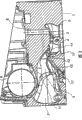
Fig. 1 illustrates the schematic representation according to the cylinder head of gas engine of the present invention of the unilateral observation that is fixed from cylinder block;
Fig. 2 illustrates the schematic cross sectional views on the A-A of plane of the cylinder head shown in Fig. 1;
Fig. 3 illustrates the schematic cross sectional views on the B-B of plane of the cylinder head shown in Fig. 1;
Fig. 4 illustrates the schematic cross sectional views on the C-C of plane of the cylinder head shown in Fig. 1;
Fig. 5 illustrates the schematic cross sectional views on the D-D of plane of the cylinder head shown in Fig. 1.
Embodiment
Fig. 1 shows from cylinder block and comprises the cylinder head of the gas engine that (for example, adopting one group of bolt) thereon side (surface 1) observes that is fixed cylinder thus.Shown cylinder head is characterised in that (Fig. 2 is shown in 3,4): one with deliver air to cylinder in the distributor 2 (mainly being a manifold) that links to each other of one group of suction tude 3.Shown in the figure but in optional situation, described suction tude is separated, thus two intake valve supply cylinders can be passed through, and this is the motor that a kind of each cylinder has four valves.For this reason, for each cylinder, cylinder head is characterised in that: be provided with two openings 4 and 5, described suction tude stops with described opening.The valve stem (stem of the valve) that is designed for opening and closing cylinder air inlet periodically passes the through hole 6 that is positioned at described opening; Valve stem suitably engages with the wall of through hole 6 and gives valve by the transmission of movement that rocking arm or suitable structure can be positioned at the camshaft on the cylinder head in a side relative with surface 1; The ring-shaped bearing portion 9 that forms the part of cylinder head and be used for camshaft is supported is at Fig. 2, in 3,4 as seen; The support of the several mutual alignment of decision design.Be equipped with intake valve at opening 4 and 5 place's cylinders.
Equally, can also observe exhaust port 7 and 8, waste gas enters an outlet pipe by described opening.The outlet pipe of each cylinder can feed a common exhaust manifold.Similar with the valve stem of intake valve, the valve stem of exhaust valve can make valve link to each other with camshaft by hole 10.
Wherein one at Fig. 2, and visible many suction tude 3 are limited by wall 11 in the sectional view in 3,4,5 in the Different Plane.According to the present invention, the injection channel 12 that is preferably the fuel of gaseous state passes described wall; Figure 2 illustrates a longitudinal sectional view of described injection channel.According to this preferred embodiment of the invention, wall 11 is characterised in that outlet 14 positions of the passage 12 in described suction tude are provided with a projection 13 towards suction tude 3 inside.Consider the flow dynamics of the gas in the pipeline under the working environment, described projection can make outlet be positioned at the inside of suction tude in optimal mode, and optimizing fuel and Air mixing, thereby this projection is favourable.In addition, described projection can be easily obtains with a form of single-piece part with part of cylinder head, and described cylinder head partly has the part that tube wall is provided with injection channel, and described projection can be the parts that for example form by casting.Like this, can also easily obtain to have the projection of suitable shape, for example a kind of shape of loss minimum of the front portion that can make in suction tude the gas that flows.According to a further aspect in the invention, outlet 14 can be positioned at the curved part of suction tude 3 or under any circumstance all be positioned at the part that the airspeed direction changes, thereby utilizes the melange effect that is caused by the turbulent flow that is produced (turbulence).The position that has a curved part in suction tude 3 is if the projection of being provided with then can preferably place the outlet of projection or passage the inboard of curved part.Projection can be any suitable shape.According to a preferred embodiment, projection can be for as Fig. 2, the fin shape shown in 3,4, and wherein Fig. 2 shows its sectional view, and other two accompanying drawings show its side view.As shown in Figure 2, being one basically based on the sectional view of the projection on the plane of the axis that comprises passage 12 has and can be straight line or also can be the triangle on two limits of the various forms of curves of thinking fit; This section is substantially perpendicular to the tube wall 11 that is positioned at the raised position place.According to a specific embodiments of the present invention, than short, and export 14 at least in part with relative towards the limit of the connection opening 4 of suction tude and cylinder and 5 towards the limit of distributor 2 towards the limit of the connection opening 4 of suction tude and cylinder and 5.Passage 12 can be or can not be straight; If straight, its axis can be preferably located in the plane of a direction that is arranged essentially parallel to the air in the running state lower inlet duct 3 so.As shown in Figure 4, the width of projection on the direction vertical with above-mentioned section preferably is narrower than other size.Described width can be constant basically as shown in drawings, or variable; For example the wideest at bottom place, narrow down gradually towards the top at outlet 14 places of passage then.
This passage is characterised in that and is provided with and the external fuel feeding mechanism, for example the connection set 17 of gas pipeline.Situation shown in this example is a female thread portion of passage, and wherein the end of a pipe can screw in this female thread portion, but also can adopt any known suitable system that is considered to.
The invention still further relates to a kind of manufacture method of foregoing cylinder head, this method comprises a part of using casting technique to obtain described cylinder head, described part comprises the part of the described wall 11 that has at least one suction tude, next for example adopts driling machine to form opening passes described wall with formation fuel injection passages on described wall.Preferably, the wall of described suction tude is characterised in that, is provided with a projection, and described passage is at the position of described projection opening.
Shown cylinder head is applicable to six cylinder engine, but the present invention is also applicable to the motor with any cylinder number, preferably more than one.
Those skilled in the art can also be identified for other suitable structure of suction tude, projection and injection channel like a dream according to the type of the motor that will build.
The present invention optimizes the supply of fuel of motor such as gas electricity generator, and air must mix with fuel before entering into cylinder mutually in described motor.Carry out near being injected in each cylinder, and no longer need to resemble in the multipoint mode spraying technique of the prior art insert the pipe of the distributor that passes injection air, thereby avoided the issuable vibration and the damage that bring with the interference and this technology of air-flow.Also make to form the part of air inlet tube wall, preferably form the projection of the part of air inlet tube wall, this permissions makes the suction tude shape be optimized on flow dynamics, and the feasible mixing that can obtain good air and fuel.This ejecting system quite firmly and than employed system so far has the more life-span of lengthening.
Claims (11)
1. explosive motor comprises:
One or more cylinders;
A distributor (2) that is used for air inlet;
Described distributor is connected to one or more suction tude (3) of the input part of described cylinder, described suction tude is limited by at least one wall (11);
Be respectively applied for a fuel injection passages (12) of each described suction tude, described passage passes described wall,
It is characterized in that the outlet (14) of the described passage of described wall in described suction tude locates to have a projection towards described suction tude inside (13).
2. explosive motor according to claim 1 is characterized in that, described motor is a gas engine.
3. explosive motor according to claim 1 is characterized in that, described projection is at the axis that comprises described passage and roughly triangular in shape perpendicular to the section in the plane of air inlet tube wall.
4. explosive motor according to claim 1 is characterized in that, described projection is one to have the single-piece part of at least a portion of the described wall of suction tude.
5. explosive motor according to claim 1 is characterized in that, described suction tude is characterised in that, is provided with a curved part, and the outlet of injection channel is positioned at the position of described curved part.
6. explosive motor according to claim 5 is characterized in that described projection is positioned at the inside of described curved part.
7. a cylinder head that is used for explosive motor comprises that one is used for the distributor (2) of air inlet; The suction tude (3) that one or more links to each other with described distributor, described suction tude are limited by at least one wall (11) and have at least one surface that is positioned at described cylinder head (1) and go up, be suitable for the opening (4,5) that links to each other with one or more cylinders;
Be respectively applied for a fuel injection passages (12) of each described suction tude, described passage passes described wall,
It is characterized in that the outlet (14) of the described passage of described wall in described suction tude locates to have a projection towards described suction tude inside (13).
8. a manufacturing is according to the method for the cylinder head of claim 7, comprise: adopt casting technique to obtain the part of described cylinder head, described part comprises the part of the described wall (11) of at least one suction tude (3), it is characterized in that, described method comprises, next passes the opening that described wall forms described fuel injection passages (12) in the position of described projection.
9. a motor is characterized in that, comprises the described cylinder head of claim 7.
10. fuel system with internal-combustion engine of an air inlet distributor, one or more suction tude that link to each other with described distributor, that limit by at least one wall, it is characterized in that, this internal-combustion engine comprises a fuel injection passages that is respectively applied for each described suction tude, described passage passes described wall, the outlet port of the described passage of described wall in described suction tude has a projection towards described suction tude inside, and fuel sprays by described wall.
11. fuel system according to claim 10 is characterized in that described fuel is gas.
Applications Claiming Priority (2)
| Application Number | Priority Date | Filing Date | Title |
|---|---|---|---|
| ITMI2003A002616 | 2003-12-30 | ||
| IT002616A ITMI20032616A1 (en) | 2003-12-30 | 2003-12-30 | GAS MOTOR, CYLINDER HEAD FOR GAS ENGINE, METHOD OF PRODUCTION OF THIS CYLINDER HEAD, AND METHOD OF GAS SUPPLY AS A GAS ENGINE |
Publications (2)
| Publication Number | Publication Date |
|---|---|
| CN1651751A CN1651751A (en) | 2005-08-10 |
| CN100480503C true CN100480503C (en) | 2009-04-22 |
Family
ID=34566917
Family Applications (1)
| Application Number | Title | Priority Date | Filing Date |
|---|---|---|---|
| CNB2004100758699A Expired - Lifetime CN100480503C (en) | 2003-12-30 | 2004-12-30 | Internal combustion engine , cylinder head and fabricating method and gas supply system |
Country Status (6)
| Country | Link |
|---|---|
| EP (1) | EP1550801B1 (en) |
| CN (1) | CN100480503C (en) |
| AT (1) | ATE431493T1 (en) |
| DE (1) | DE602004021081D1 (en) |
| ES (1) | ES2325394T3 (en) |
| IT (1) | ITMI20032616A1 (en) |
Families Citing this family (4)
| Publication number | Priority date | Publication date | Assignee | Title |
|---|---|---|---|---|
| CN103487254B (en) * | 2013-07-29 | 2015-09-30 | 中国人民解放军装备学院 | A kind of test unit with controllable frequency pressure oscillation mechanism |
| CN105201677B (en) * | 2015-11-09 | 2018-04-20 | 玉柴联合动力股份有限公司 | A kind of gas engine cylinder cap |
| CN107939556A (en) * | 2017-12-25 | 2018-04-20 | 潍柴动力股份有限公司 | A kind of multi-point injection natural gas engine |
| NO344301B1 (en) * | 2018-09-20 | 2019-10-28 | Bergen Engines As | A gas supply system for a gas engine |
Family Cites Families (7)
| Publication number | Priority date | Publication date | Assignee | Title |
|---|---|---|---|---|
| EP0510585B1 (en) * | 1991-04-20 | 1999-07-07 | Yamaha Hatsudoki Kabushiki Kaisha | Gas engine |
| CH689565A5 (en) * | 1995-03-09 | 1999-06-15 | Bosch Gmbh Robert | Method and apparatus for formation of a turbulent fuel-air mixture in the combustion chamber of each cylinder of a valve-controlled internal combustion engine. |
| FR2770876B1 (en) * | 1997-11-10 | 1999-12-24 | Renault | FUEL INJECTION DEVICE FOR INTERNAL COMBUSTION ENGINE |
| US6675748B2 (en) * | 2000-02-11 | 2004-01-13 | Westport Research Inc. | Method and apparatus for fuel injection into an internal combustion engine |
| GB0004271D0 (en) * | 2000-02-23 | 2000-04-12 | Bastable Richard A | Recirculated compression direct gas injection system |
| FR2819015B1 (en) * | 2000-12-28 | 2003-05-23 | Renault | GAS INTAKE SYSTEM IN A COMBUSTION CHAMBER COMPRISING MEANS OF DEFLECTION |
| US6609499B2 (en) * | 2001-11-08 | 2003-08-26 | Ford Global Technologies, Llc | Gaseous-fuel injection system and method |
-
2003
- 2003-12-30 IT IT002616A patent/ITMI20032616A1/en unknown
-
2004
- 2004-12-27 AT AT04106989T patent/ATE431493T1/en not_active IP Right Cessation
- 2004-12-27 ES ES04106989T patent/ES2325394T3/en not_active Expired - Lifetime
- 2004-12-27 DE DE602004021081T patent/DE602004021081D1/en not_active Expired - Lifetime
- 2004-12-27 EP EP04106989A patent/EP1550801B1/en not_active Expired - Lifetime
- 2004-12-30 CN CNB2004100758699A patent/CN100480503C/en not_active Expired - Lifetime
Also Published As
| Publication number | Publication date |
|---|---|
| ATE431493T1 (en) | 2009-05-15 |
| EP1550801A1 (en) | 2005-07-06 |
| EP1550801B1 (en) | 2009-05-13 |
| ES2325394T3 (en) | 2009-09-03 |
| ITMI20032616A1 (en) | 2005-06-30 |
| CN1651751A (en) | 2005-08-10 |
| DE602004021081D1 (en) | 2009-06-25 |
Similar Documents
| Publication | Publication Date | Title |
|---|---|---|
| EP0137394B1 (en) | Intake arrangement for internal combustion engine | |
| JPH07119472A (en) | Intake device for engine | |
| US4438743A (en) | Internal combustion engine | |
| JP2002371917A (en) | Gas injection device for gas engine | |
| JPS589248B2 (en) | Intake system for multi-cylinder internal combustion engine | |
| US5146897A (en) | Intake manifold of intake system for multi-cylinder internal combustion engine | |
| US20140069393A1 (en) | Fuel injection apparatus for internal combustion engine | |
| CN100480503C (en) | Internal combustion engine , cylinder head and fabricating method and gas supply system | |
| CN103485944A (en) | Fuel gas supply system of double-fuel diesel engine | |
| US6912978B2 (en) | Air feeding arrangement for piston engine | |
| JP2006125333A (en) | Internal combustion engine | |
| JP4529746B2 (en) | Intake device for internal combustion engine | |
| US4530325A (en) | Suction system for internal combustion engine | |
| KR20120081374A (en) | Intake apparatus of gas engine having adapter type injector module | |
| CN103534477A (en) | Fuel injection device for internal combustion engine | |
| JP3699226B2 (en) | Catamaran vaporizer | |
| EP1073841B1 (en) | Air shroud for air assist fuel injector | |
| EP1336748A2 (en) | Air feeding arrangement for piston engine | |
| GB2408999A (en) | Cylinder head for an internal cumbustion engine | |
| CN102518528A (en) | General petrol engine cylinder head and petrol engine | |
| JPS6341569Y2 (en) | ||
| KR20120081373A (en) | Intake apparatus of gas engine | |
| EP0202289A1 (en) | Inlet ducts in internal combustion engines | |
| JPS6124669Y2 (en) | ||
| RU140417U1 (en) | SYSTEM (OPTIONS) |
Legal Events
| Date | Code | Title | Description |
|---|---|---|---|
| C06 | Publication | ||
| PB01 | Publication | ||
| C10 | Entry into substantive examination | ||
| SE01 | Entry into force of request for substantive examination | ||
| C14 | Grant of patent or utility model | ||
| GR01 | Patent grant | ||
| ASS | Succession or assignment of patent right |
Owner name: FPT INDUSTRIE S.P.A. Free format text: FORMER OWNER: IVECO S. P. A. Effective date: 20120214 |
|
| C41 | Transfer of patent application or patent right or utility model | ||
| TR01 | Transfer of patent right |
Effective date of registration: 20120214 Address after: Italy Tori Patentee after: FPT Industries Address before: Torino Patentee before: IVECO S.P.A. |
|
| CX01 | Expiry of patent term |
Granted publication date: 20090422 |
|
| CX01 | Expiry of patent term |