CN100476983C - Optical disc recording device - Google Patents
Optical disc recording device Download PDFInfo
- Publication number
- CN100476983C CN100476983C CNB031490840A CN03149084A CN100476983C CN 100476983 C CN100476983 C CN 100476983C CN B031490840 A CNB031490840 A CN B031490840A CN 03149084 A CN03149084 A CN 03149084A CN 100476983 C CN100476983 C CN 100476983C
- Authority
- CN
- China
- Prior art keywords
- laser
- value
- laser power
- temperature
- transmitting set
- Prior art date
- Legal status (The legal status is an assumption and is not a legal conclusion. Google has not performed a legal analysis and makes no representation as to the accuracy of the status listed.)
- Expired - Fee Related
Links
- 230000003287 optical effect Effects 0.000 title claims abstract description 98
- 230000008859 change Effects 0.000 claims abstract description 48
- 238000002310 reflectometry Methods 0.000 claims description 11
- 238000002845 discoloration Methods 0.000 abstract description 2
- 238000000034 method Methods 0.000 description 72
- 230000008569 process Effects 0.000 description 57
- 230000000007 visual effect Effects 0.000 description 39
- 230000001678 irradiating effect Effects 0.000 description 15
- 230000035945 sensitivity Effects 0.000 description 14
- 239000000758 substrate Substances 0.000 description 12
- 238000010586 diagram Methods 0.000 description 10
- 230000005855 radiation Effects 0.000 description 9
- 238000012937 correction Methods 0.000 description 8
- 238000006243 chemical reaction Methods 0.000 description 5
- 230000001681 protective effect Effects 0.000 description 5
- 238000001514 detection method Methods 0.000 description 4
- 230000006870 function Effects 0.000 description 4
- 238000012544 monitoring process Methods 0.000 description 4
- 230000015572 biosynthetic process Effects 0.000 description 3
- 238000005755 formation reaction Methods 0.000 description 3
- 230000033001 locomotion Effects 0.000 description 3
- 238000003860 storage Methods 0.000 description 3
- 238000004364 calculation method Methods 0.000 description 2
- 239000003086 colorant Substances 0.000 description 2
- 238000011161 development Methods 0.000 description 2
- 230000018109 developmental process Effects 0.000 description 2
- 230000003760 hair shine Effects 0.000 description 2
- 230000000977 initiatory effect Effects 0.000 description 2
- 230000014759 maintenance of location Effects 0.000 description 2
- 238000005259 measurement Methods 0.000 description 2
- 238000007634 remodeling Methods 0.000 description 2
- 230000000630 rising effect Effects 0.000 description 2
- 238000012360 testing method Methods 0.000 description 2
- 238000002679 ablation Methods 0.000 description 1
- 230000001133 acceleration Effects 0.000 description 1
- 230000003139 buffering effect Effects 0.000 description 1
- 238000000151 deposition Methods 0.000 description 1
- 238000013461 design Methods 0.000 description 1
- 238000010017 direct printing Methods 0.000 description 1
- 230000000694 effects Effects 0.000 description 1
- 238000005516 engineering process Methods 0.000 description 1
- 230000008676 import Effects 0.000 description 1
- 230000006872 improvement Effects 0.000 description 1
- 238000003475 lamination Methods 0.000 description 1
- 238000012423 maintenance Methods 0.000 description 1
- 238000003825 pressing Methods 0.000 description 1
- 238000007639 printing Methods 0.000 description 1
- 238000012545 processing Methods 0.000 description 1
- 230000001915 proofreading effect Effects 0.000 description 1
- 230000008929 regeneration Effects 0.000 description 1
- 238000011069 regeneration method Methods 0.000 description 1
- 238000004088 simulation Methods 0.000 description 1
- 238000004804 winding Methods 0.000 description 1
Images


Classifications
-
- G—PHYSICS
- G11—INFORMATION STORAGE
- G11B—INFORMATION STORAGE BASED ON RELATIVE MOVEMENT BETWEEN RECORD CARRIER AND TRANSDUCER
- G11B7/00—Recording or reproducing by optical means, e.g. recording using a thermal beam of optical radiation by modifying optical properties or the physical structure, reproducing using an optical beam at lower power by sensing optical properties; Record carriers therefor
- G11B7/12—Heads, e.g. forming of the optical beam spot or modulation of the optical beam
- G11B7/125—Optical beam sources therefor, e.g. laser control circuitry specially adapted for optical storage devices; Modulators, e.g. means for controlling the size or intensity of optical spots or optical traces
- G11B7/126—Circuits, methods or arrangements for laser control or stabilisation
- G11B7/1267—Power calibration
-
- G—PHYSICS
- G11—INFORMATION STORAGE
- G11B—INFORMATION STORAGE BASED ON RELATIVE MOVEMENT BETWEEN RECORD CARRIER AND TRANSDUCER
- G11B23/00—Record carriers not specific to the method of recording or reproducing; Accessories, e.g. containers, specially adapted for co-operation with the recording or reproducing apparatus ; Intermediate mediums; Apparatus or processes specially adapted for their manufacture
- G11B23/38—Visual features other than those contained in record tracks or represented by sprocket holes the visual signals being auxiliary signals
- G11B23/40—Identifying or analogous means applied to or incorporated in the record carrier and not intended for visual display simultaneously with the playing-back of the record carrier, e.g. label, leader, photograph
-
- G—PHYSICS
- G11—INFORMATION STORAGE
- G11B—INFORMATION STORAGE BASED ON RELATIVE MOVEMENT BETWEEN RECORD CARRIER AND TRANSDUCER
- G11B7/00—Recording or reproducing by optical means, e.g. recording using a thermal beam of optical radiation by modifying optical properties or the physical structure, reproducing using an optical beam at lower power by sensing optical properties; Record carriers therefor
- G11B7/002—Recording, reproducing or erasing systems characterised by the shape or form of the carrier
- G11B7/0037—Recording, reproducing or erasing systems characterised by the shape or form of the carrier with discs
Abstract
An optical disc recording apparatus 100 comprises a temperature detecting circuit 141 for detecting a temperature of an optical disc 200 and corrects a laser power for discolorating a discoloration layer of the optical disc 200 in accordance with the temperature detected by the temperature detecting circuit 141 in order to cancel a change in the temperature of the optical disc 200. The optical disc recording apparatus 100 can record a high quality visible image on an optical disc without a printer.
Description
The present invention is based on the Japanese patent application 2002-188167 that 2002.6.27 proposes, this paper draws its full content and is list of references.
Technical field
The present invention relates to a kind of optical disc recording apparatus, it records visual image in the CD.
Background technology
Usually existing recording information to such as the optical disc recording apparatus on readable optical disk (CD-R), the CD-RW CD-R such as (CD-RW).Optical disc recording apparatus with laser beam irradiation to the recording surface of CD, and by control with the corresponding laser beam of data of plan record recorded information.
On the other hand, the relative side on the video disc recording surface is provided with identified surface.Described identified surface is as write area, and the user writes the content of video disc recording thereon.In recent years, the user uses the image of personal computer (calling PC in the following text) design identified surface usually, and with printer it is printed on the sign page or leaf, will identify page or leaf again and adhere on the described identified surface.Also have, the user generally uses printer that image is directly printed on the identified surface of CD.
For original image being printed on the described identified surface, printer must be arranged.In addition, when using the sign page or leaf, the user has failure when being bonded to it on the identified surface, makes operating process become complicated.On the other hand, on described identified surface, carry out when directly printing, just be difficult to take place described failure.But the printer with direct printing function on identified surface must must be bought.
On the recording surface of CD, realize the information record by the reflectivity that changes recording layer with laser.The present inventor changes color when aiming at the information record, and considers with laser beam visual image to be recorded on the CD.
But because normal optical disk pen recorder emitted laser bundle has equal-wattage, when the CD temperature change, feasible duration (the calling recording sensitivity in the following text) change that reaches the colour development temperature by laser beam.The variation of recording sensitivity causes the gap of colour development position and contrast, and the profile of visual image is faded, and perhaps the contrast of visual field reduces.
On the other hand, some normal optical disk pen recorder is to each CD setting laser power.But this class optical disc recording apparatus keeps described laser power to fix during writing down.So recording sensitivity keeps identical with the position of CD temperature variation.
Summary of the invention
The object of the present invention is to provide a kind of optical disc recording apparatus, it can be recorded in visual image on the CD in high quality, and need not printer.
According to a kind of scheme of the present invention, a kind of optical disc recording apparatus is provided, comprising: the optical transmitting set of emission of lasering beam to the CD with photochromic layer; Move described optical transmitting set by the diametric(al) along described CD, control is by the positioner of described optical transmitting set emitted laser bundle irradiation position; Laser power control, it is according to the view data from the external device (ED) input, the laser power control of described optical transmitting set emitted laser bundle is made as the value of writing or servo value, and wherein the value of writing and servo value are respectively the performance numbers that changes and do not change Laser emission zone reflectivity; Detect the Temperature Detector of CD temperature; And the laser power corrector, control described laser power control according to the temperature that detects by described Temperature Detector, to proofread and correct power, make the photochromic layer variable color, and eliminate the CD variation of temperature by laser by described optical transmitting set emitted laser.
According to this configuration, because the CD temperature variation is eliminated, make that laser power obtains proofreading and correct when being made above-mentioned photochromic layer variable color by laser beam.So, the temperature of laser irradiating position is fixed, and recording sensitivity is fixed.
According to another program of the present invention, a kind of optical disc recording apparatus is provided, comprising: the optical transmitting set of emission of lasering beam to the CD with photochromic layer; Move described optical transmitting set by the diametric(al) along described CD, control is by the positioner of described optical transmitting set emitted laser bundle irradiation position; The CD spinner of rotary CD; Laser power control, it is according to the view data from the external device (ED) input, the laser power control of described optical transmitting set emitted laser bundle is made as the value of writing or servo value, and wherein the value of writing and servo value are respectively the performance numbers that changes and do not change Laser emission zone reflectivity; Detect the Temperature Detector of the temperature of CD; And Rotation Controllers, control described CD spinner according to the temperature that detects by described Temperature Detector, change the rotating speed of CD, to eliminate the CD temperature variation.
According to this configuration, because the CD temperature variation is eliminated, make the rotating speed of CD be able to Be Controlled.So, the temperature of laser irradiating position is fixed, and recording sensitivity is fixed.
According to another scheme of the present invention, a kind of optical disc recording apparatus is provided, comprising: the optical transmitting set of emission of lasering beam to the CD with photochromic layer; Move described optical transmitting set by the diametric(al) along described CD, control is by the positioner of described optical transmitting set emitted laser bundle irradiation position; Laser power control, it is according to the view data from the external device (ED) input, the laser power control of described optical transmitting set emitted laser bundle is made as the value of writing or servo value, and wherein the value of writing and servo value are respectively the performance numbers that changes and do not change Laser emission zone reflectivity; Receive the laser-bounce light of CD reflection and the optical receiver that the light receiving signal of light-receiving value is represented in output; And laser power corrector, according to controlling described laser power control from the view data of external device (ED) input, to revise the laser power of described optical transmitting set emitted laser bundle, when laser is in the following time of laser power that makes the photochromic layer variable color, keep light-receiving value rate of change to be the rate of change in pre-determining scope.
According to this configuration,, just make, make the rotating speed of CD be able to Be Controlled because the CD temperature variation is eliminated because the laser power of laser beam is controlled.So, can make the rate of change of light-receiving amount remain on rate of change with the scope of pre-determining, can make photochromic layer variable color positively.
According to a scheme more of the present invention, a kind of optical disc recording apparatus is provided, comprising: the optical transmitting set of emission of lasering beam to the CD with photochromic layer; Move described optical transmitting set by the diametric(al) along described CD, control is by the positioner of described optical transmitting set emitted laser bundle irradiation position; The CD spinner of rotary CD; Laser power control, it is according to the view data from the external device (ED) input, the laser power control of described optical transmitting set emitted laser bundle is made as the value of writing or servo value, and wherein the value of writing and servo value are respectively the performance numbers that changes and do not change Laser emission zone reflectivity; Receive the laser-bounce light of CD reflection and the optical receiver that the light receiving signal of light-receiving value is represented in output; And Rotation Controllers, according to view data control CD spinner from the external device (ED) input, to change the rotating speed of CD,, keep light-receiving value rate of change to be the rate of change in pre-determining scope when laser is in the following time of laser power that makes described photochromic layer variable color.
According to this configuration, because the rotating speed of CD is controlled, remains on the interior rate of change of preset range with regard to the rate of change that makes the light-receiving amount, thereby make photochromic layer variable color positively.
According to the present invention, can visual image be recorded on the CD with high-quality, and need not printer.
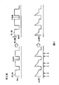
Description of drawings
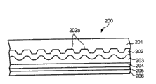
Fig. 1 is the sectional drawing of the used CD of an embodiment of the present invention optical disc recording apparatus;
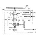
Fig. 2 is the block scheme of optical disc recording apparatus electrical structure;
Fig. 3 is the synoptic diagram that expression optics picks up picture device structure;
Fig. 4 is in order to the coordinate diagram of explanation by the definite CD of view data;
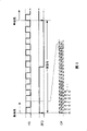
Fig. 5 is the synoptic diagram in order to explanation detection laser irradiation position;
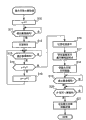
Fig. 6 is illustrated in when calculating laser power the process flow diagram of the control module course of work;
Fig. 7 is when being illustrated in the laser power correcting process, the process flow diagram of the control module course of work;
Fig. 8 is when being illustrated in ablation process, the process flow diagram of the control module course of work;
Fig. 9 is the synoptic diagram in order to the explanation modified example.
Embodiment
Before the relevant an embodiment of the present invention optical disc recording apparatus 100 of explanation, the structure of CD 200 is described first, by described optical disc recording apparatus 100 visual image is recorded on the identified surface of this CD.
Fig. 1 is the sectional drawing of CD 200.As shown in the figure, protective seam 201, recording layer 202, reflection horizon 203, protective seam 204, heat-sensitive layer 205 and protective seam 206 in this order lamination constitute CD 200.In addition, Fig. 1 is a kind of model, and the physical size ratio of each layer does not need identical with shown in this figure.
On the surface (top among the figure) of recording layer 202, curl forms groove (guiding groove) 202a.In the time of on recording the information in this CD 200, laser shines along this groove 202a.
That is to say,, the surface (calling " recording surface " in the following text) on protective seam 201 1 sides of CD 200 is set for, make the optics of it and optical disc recording apparatus 100 pick up picture device (back detailed description) and meet for recording the information on the CD 200.Then, write down described information by moving along groove 202a to pick up as the device emitted laser by optics.
On the other hand, when on the surface that visual image is recorded in CD 200, the optics of CD 200 being set for the surface (calling " identified surface " in the following text) that makes protective seam 206 and optical disc recording apparatus 100 picks up as device and meets.Then, by laser radiation on heat-sensitive layer 205, make the desired location variable color of heat-sensitive layer 205, form image.In addition, except that heat-sensitive layer 205, the structure of the CD 200 almost structure with common CD-R dish is identical.Therefore, the introducing district of CD 200 is identical with common CD-R dish, and absolute time (ATIP) information when writing down pre-slotting in advance, as the kind of medium and layout, desirable laser power, writing speed, making mark etc.
The optical disc recording apparatus 100 of the subsequent explanation embodiment of the invention.Optical disc recording apparatus 100 is the devices that information can be recorded on the identified surface that also visual image can be recorded in above-mentioned CD 200 on the recording surface.
In addition, optical disc recording apparatus 100 links to each other with personal computer (calling PC in the following text) 300 through the signal cable (not shown), will be recorded in record data and the view data corresponding with visual image on the described recording surface through the input of described signal cable.Any interface standard can be used for being connected between optical disc recording apparatus 100 and the PC 300, all can sample as small computer system interface (SCSI) standard, Institute of Electrical and Electric Engineers (IEEE) 1394 standards, AT accessory bag interface (ATAPI-AT Attachment PacketInterface) standard, universal serial bus structural (USB-Universal Serial Bus) standard etc.
Fig. 2 is the block scheme of expression optical disc recording apparatus 100 electrical structures.Spindle motor 101 rotations among this figure drive CD 200.Frequency generator spare 102 utilizes the spike pulse electric current of spindle motor 101, output frequency and the corresponding pulse signal FG of spindle motor rotating speed (winding number of unit interval).The optical disc recording apparatus 100 of this embodiment of the present invention is by constant angular velocity (CAV) method execution information record and image recording.Therefore, spindle motor 101 drives CD 200 rotatably with fixing angular velocity.
It is that laser beam is transmitted in unit on the CD 200 that optics picks up as device 103.Fig. 3 illustrates its structure.As shown in the drawing, optics pick up as device 103 laser diode 104, diffraction grating 105 of radiation laser be equipped with, laser convergence in CD 200 lip-deep optical systems 110, and the catoptrical light receiving element 106 that receives institute's reflector laser.In addition, laser diode 104 emission and the corresponding laser of drive signal Li from laser driver (referring to Fig. 2).
As shown in Figure 3, object lens 114 are subjected to focus actuator 121 and follow the tracks of actuator 122 controls.Described focus actuator 121 moves object lens 114 (referring to Fig. 2) according to the focus error signal Fc from servo circuit 107 towards optical axis direction.On the other hand, described tracking actuator 122 moves object lens 114 according to the tracking error signal Tr from servo circuit 107 towards diametric(al).Owing to do like this, realize focus control and tracking Control.
In addition, will pick up the light receiving signal Rv of the light receiving element 106 that looks like device 103 through RF amplifier 108 input servo circuits 107, servo circuit 107 generations and corresponding focus error signal Fc of light receiving signal Rv and tracking error signal Tr from optics.
By picking up as device 103 by the diametric(al) mobile optical of stepper motor 131 towards CD 200, and by spindle motor 101 rotary CDs 200, optics can be picked up each position that moves to CD 200 as the position of the Laser emission of device 103, these structural details are formed position controls.
The Various types of data subsequent, that memory buffer 135 and frame memory 134 are provided by PC 300 by interface 139 interim storages.In detail, memory buffer 135 will be recorded in the lip-deep record data of video disc recording with the storage of first-in first-out (FIFO) method.136 pairs of record data of reading from buffering storer 135 of scrambler are carried out the EFM modulation, to output to strategy circuit 137.The data that 137 pairs of scramblers 136 of strategy circuit provide are carried out the time shaft correcting process, to output to laser driver 138.
On the other hand, the view data of the visual image of formation on CD 200 is intended in frame memory 134 storages.This data are one group of data in order to the pixel concentration (contrast) of definite plan drafting on CD 200.As shown in Figure 4, each pixel P is defined as corresponding with each point of crossing of drawing between the radiant rays at center with the concentric circles of CD 200.For the coordinate of each point of crossing in the CD 200 is described, each concentric circles from the CD inboard to the outside is defined as the 1st row, the 2nd row, the 3rd row in regular turn ... m capable (the last item is capable), and a radiant rays is being defined as under the situation of datum line, and the sequential definition of other each radiate linear being docile and obedient hour hands is the 1st row, the 2nd row, the 3rd row ... n is listed as (last row).The position of such each pixel of drafting simulation ground expression, in fact each pixel is arranged more tight.
Define the reasons are as follows of each pixel arrangement by this way.According to standard, when information being recorded on the CD 200, watch from described recording surface, the rotation of CD inhour, and the structure that optics picks up as device is to move from inside to outside.When guaranteeing said structure, even identified surface is being set for will picked up under the situation of meeting with optics as device 103, CD 200 inhour rotations, optics picks up as device 103 and moves from the inside to surface simultaneously.So when picking up from optics when watching CD 200 as device 103, CD 200 inhour rotations also move on to the outside from the inboard of CD 200.The order that above-mentioned pixel is arranged is corresponding with the scanning sequency that optics picks up picture device 103.
Corresponding to this, the form that view data is arranged with the capable n row of m is stored in the frame memory 134.Read the view data of being deposited in the frame memory 134 by control module 130 capable connecing capablely, thereby pixel is offered laser driver 138 one by one.
On the other hand, the laser power of following control laser diode 104.Just described optics picks up as device 103 has preceding monitoring diode (not shown), and described preceding monitoring diode receives the supervision light (from the light of laser diode 104 chip backs) of laser diode 104, and generation and the corresponding electric current of light income.Then, the electric current that is produced is exported to laser power control circuit 140 as standby current.
Laser power control circuit 140 control laser diodes 104 emitted laser power are corresponding with the standby current value of being imported.Conversely, laser power control circuit 140 utilizes described standby current value, carries out the FEEDBACK CONTROL of laser driver 103, makes to pick up picture device 103 with specified laser power emission laser from optics.Specified laser power value is the desirable laser power value by control module 130 instructions, and in fact instructs the standby current value corresponding with laser power.
Temperature sensing circuit 141 and temperature variant circuit (not shown) link to each other as electroregulator, and vary with temperature the temperature of the circuit substrate of circuit measuring optical disc recording apparatus 100 by this, again with the temperature notice control module 130 that records.
The heat that the circuit of various motors of reason and laser diode 104 sends, and the internal temperature of optical disc recording apparatus 100 is become than external temperature height.On the other hand, because CD 200 is positioned at the inside of optical disc recording apparatus 100, so make the temperature that it becomes almost same with the internal temperature of optical disc recording apparatus 100 because of heat death (heat death).Thereby, according to embodiments of the invention, because CD 200, circuit substrate etc. are closely located in optical disc recording apparatus 100, be positioned at thermal source so remove, outside near the part the laser diode 104, the temperature that the temperature of CD 200 is treated as with circuit substrate is identical, by the temperature of metering circuit substrate, is measured the temperature of CD 200.Though just can make described temperature variant device be positioned at energy measurement CD 200 temperature Anywhere, most convenient also is that optimum position is on circuit substrate.Therefore, be the temperature of metering circuit substrate in an embodiment of the present invention.
The course of work of subsequent explanation embodiment of the invention optical disc recording apparatus 100.The principal feature of optical disc recording apparatus 100 is that visual image is recorded on the CD 200.On the other hand, except the general information writing function, less important function is the Versatile apparatus that the visual image writing function is also arranged.Below will sketch the course of work when information writes down, and the course of work when describing visual image record as characteristics of the present invention in detail.
In optical disc recording apparatus 100, when setting CD 200, control module 130 makes the angular velocity of CD 200 become predetermined angular velocity by the Spin Control of servomotor 107 implementation spindle motors 101.In addition, control module 130 picks up as the motion initial order of device 103 to the position that is equivalent to introduce the district, rotating stepper motor 131 optics by electric machine controller 133 is carried out.
Next step, control module 130 judges whether to write down atip information., described recording surface is judged as to make it to be picked up towards optics as device is provided with for certainly the time in judged result, process enters the process that information writes down.
On the other hand, judged result is judged as identified surface to make it to be picked up towards optics as device and is provided with when negating, and process enters the process of visual image record.
Described information recording process is identical with commonsense method almost.When control module 130 is judged the record atip information, at first read atip information.As mentioned above, owing to medium kind of information, desirable laser power and fabricator's trade mark all are written in the atip information, so control module 130 is set the ratings of the relevant used laser power of these information.Conversely, control module 130 is carried out the process of the described ratings of desirable laser power settings that is write in the atip information and is not changed, perhaps carry out reference with fabricator's trade mark with to be written into the information of atip information, as fabricator's trade mark is the corresponding form of laser power on basis, selects the process of laser power ratings.So, be able to the laser power ratings of setting laser power control circuit 140.By doing like this, then control module 130 is easily according to the ratings of described atip information setting laser power.
Here, along with when information writes down and the rayed position in visual image when record make outside light-struck position move towards for the basis, described control module 130 also increases the ratings of described laser power.Because embodiments of the invention are suitable for the CAV method, so unless make laser power corresponding to change of line speed, the laser power of per unit area (recording power) changes.
On the other hand, when providing record data by PC 300, control module 130 is recorded in data in the memory buffer 135, and by calling over of writing down, so that carry out the EFM rectification by scrambler 136.Then, carry out the time shaft correction by strategy circuit 137.
Next, control module 130 control laser drivers 138 so that according to the data of strategy circuit 137, pick up optics as 103 emitted laser power of device and change over value of writing (write level) and servo value (servo level).The said write value is the performance number that is enough to the recording layer 202 of CD 200 is changed the reflectivity of emission laser region.On the other hand, though described servo value is the performance number that does not change the reflectivity in Laser emission zone, this value is to satisfy the performance number that will obtain the light-receiving value, and described light-receiving value can be carried out tracking Control and focus servo control.
Here set the ratings control of the value of writing Stimulated Light power, described laser power is set according to the atip information of laser power control unit 140 by control module 130.By doing like this, record data are recorded on the CD 200 with lower error rate.In addition, when information writes down,, carry out the Spin Control of spindle motor 101 all the time,, and the groove 202a from interior all sides along CD 200 writes down described record data to the tracking Control and the focus control of tracking group in the time same with said process.
Working condition when then, the visual image record being described.But, when the record visual image, carry out the Spin Control and the focus control of spindle motor 101 all the time,, carry out tracking Control in order to tracking groove 202a but unlike recited above.Characteristics during the visual image recording operation are non-productive operation, as the detection of focus control and laser irradiating position.Therefore, after they are described, main operation is described.
When visual image writes down, owing to make laser radiation on described identified surface, so, when information writes down, can not carry out to following the trail of the tracking Control of groove 202a.
Therefore, in the visual image recording process, when CD 200 sense of rotation are defined as main scanning direction, and when diametric(al) is used as sub scanning direction, by stepper motor 131 optics is picked up as device 103 and moves, in order that only to diameter with required amount subscan laser irradiating position.
Here, moving and change when being about 10 μ m being made optics pick up minimum as device 103 by stepper motor 131, similarly is about 10 μ m along sub scanning direction minimum spacing and this variation of identified surface.
Therefore, according to embodiments of the invention, carry out focus control, laser beam is become the spot size of described identified surface be about 10 μ m, this is the value identical with resolution, simultaneously, laser power and described view data are correspondingly changed and be controlled, described view data is corresponding with the pixel of visual image.So, the record visual image, the pixel distance of sensitivity of described image is stubby.
On the other hand, when visual image writes down, the described datum line in the following realization CD 200 and the detection of row.Rotation detecting 102 output pulse signal FG, as mentioned above, the frequency of this signal is corresponding with rotational velocity.Phaselocked loop (PLL) circuit 142 produces the clock signal C K by the frequency multiplication of pulse signal FG, and the signal that is produced is outputed to control module 130.In addition, frequency divider 143 produces standard signal SFG by the described signal FG of frequency division, and it is offered control module 130.
Wherein, in the rotary course of described rotation detecting 102, produce 8 pulses, during as described pulse signal FG at spindle motor 101, just work as CD 200 rotations once, as shown in Figure 5, frequency divider 143 becomes 1/8 to signal FG frequency division, so that export as standard signal SFG.So the importing (booting up) that control module 130 can examination criteria signal SFG is the moment that laser irradiating position passes through CD 200 datum lines constantly.
Have, in this case, it is that each number that is listed as is by 8 merchants that remove in the delegation that the frequency multiplication in the PLL circuit 142 is set at again, and the duration of the angle that the row that 200 pairs of described pixels of the one-period of clock signal C K and CD are arranged are rotated is corresponding.Therefore, by according to described importings of the sequential counting clock signal C K that imports standard signal SFG constantly, control module 130 can detect after the laser irradiating position that optics picks up picture device 103 has passed through the datum line of CD 200, and how many sequences are arranged.
In addition, according to the meaning of strict word, the expression of the datum line of CD 200 should be said that becoming is datum line to the turning axle of spindle motor 101.Owing to adopting to be clamped by the desk (not shown) that directly links to each other with turning axle, rotates CD 200, so datum line concerns the position that the radiant rays of the turning axle of spindle motor 101 and CD 200 is maintained fixed.Therefore, need only this condition of maintenance, just a radiant rays in the CD 200 can be pronounced the datum line of CD 200.
In addition,, the importing of standard signal SFG is defined as CD 200 constantly by datum line constantly, and is the time of the angle of a row rotation during pixel is arranged the importing timing definition of clock signal C K according to embodiments of the invention.In both of these case, certainly adopt and derive (booting down) constantly.
The instruction that moves to the most inboard point (first row) of CD 200 as device 103 is picked up optics in control module 130 output.Utilize this instruction, electric machine controller 133 generations are picked up as device 103 optics and are moved to the required signal of described point, and simultaneously, motor driver 132 makes stepper motor 131 rotations, so optics picks up as device 103 and moves to described point.
Then, control module 130 is carried out laser power and is calculated process.This laser power calculating process is the process of laser power (value of writing) that obtains to make the heat-sensitive layer 205 abundant variable colors of CD 200.Here, Fig. 6 is illustrated in when calculating laser power the process flow diagram of the control module course of work.
In this process, control module 130 is set " 1 " (step S10) to variable x earlier.The variable x here is used to obtain rotation number in y the rotation (y>1) of carrying out record.Therefore, by variable x is set " 1 ", obtain rotating to be the rotation of first week.
Then, control module 130 waits the importing moment of standard signal SFG, just arrives the moment (step S11) of laser irradiating position when datum line.When standard signal SFG is imported into, the predetermined instruction of control module 130 outputs, beginning test record (step S12).Utilize this instruction, laser driver 138 changes the laser power of laser diode 104 and is controlled to the value of writing and servo value.Then, utilize laser power control circuit 140, this value of writing is changed over bigger value from a definite value gradually.So, when the heat-sensitive layer 205 of CD 200 color temperature when low owing to want variable color under the lower powered value of writing, by after the described datum line, variable color just takes place at once.On the other hand, when described heat-sensitive layer 205 color temperature when higher, variable color will be later on.That is to say and since the heat-sensitive layer 205 of CD 200 color temperature higher, because of moving from described datum line clockwise direction the position of laser variable color.Each cycle for described standard signal SFG repeats this recording process.
Afterwards, control module 130 is waited for the importing moment (step S13) of standard signal SFG.When importing standard signal SFG, whether control module 130 judgment variable x equal y (step S14).When judged result when negating, control module 130 makes variable x increase " 1 " (step S15), process enters step S13.By doing like this, with the laser radiation of last same laser power same position to CD 200.On the other hand, when judged result for certainly the time, instruction of control module 130 outputs, end record (step S16).By doing like this, the laser of same laser power repeatedly (y time) is radiated at the same position of CD 200, end record process then.
Here, the laser with same laser power repeatedly shines the reasons are as follows of same position.As mentioned above, when laser radiation is on identified surface, can not carry out the tracking Control that is used for following the trail of groove 202a.Therefore, under situation about once writing down, when reading laser, very possible is strictly to follow the trail of described position (OK).So,, can make color change interval extend to diametric(al), and when reading, can strictly follow the trail of described color change interval with same contrast owing to repeatedly arrive same position with the laser radiation of same power.
After this, control module 130 output orders make optics pick up the most inboard point that moves on to CD 200 as device 103, so that read the zone (step S17) that is recorded.And control module 130 changes to servo value (step S18) by laser driver 138 with the laser power of laser diode 104.Then, when (step S19), control module 130 waits become predetermined threshold value or littler (step S20) from the RF signal of RF amplifier 108 when control module 130 detects by described datum line.Described threshold value is a preset value in order to the judgement thermo-color.So control module 130 waits for that the position of laser radiation enters the position of thermo-color.
When the RF signal becomes described threshold value or during less than this value, control module 130 with laser power settings to shine described locational value of writing (step S21) based on the locational ratings of rayed at this moment.In above-mentioned recording process, because laser power increases from minimum value gradually with the datum line as the initial moment, so, the ratings of laser power is set at the required minimum laser power of variable color.
It is in addition, any that can to cause the laser power of thermo-color can be described ratings.But.Along with the increase of laser power, it is big that the thermal value of laser diode 104 also becomes.Therefore, not only will make the lost of life of laser diode 104, and be well known that this will become the factor of the temperature rising that makes CD 200.So, obtain the minimum painted power of the heat-sensitive layer 205 of CD 200 in the embodiments of the invention, and the laser power definition be ratings.The above-mentioned course of work is the working condition when laser power is calculated process.
Subsequent, after finishing laser power calculating process,, a laser power makeover process is arranged as the process that will carry out.No matter whether carry out recording process described later, carry out this laser power makeover process always.The summary of laser power makeover process at first is described.
The heat that the temperature at laser irradiating position place and laser produce can be by following formula (a) and (b) is represented:
The temperature (a) of heat+CD that the temperature at laser irradiating position place=laser produces
Heat=laser power * thermal conversion rate * spot size/linear velocity (b) that laser produces
The thermal conversion rate here is the thermal conversion rate of laser power on the heat-sensitive layer 205.Therefore, just like what seen, when the heat change that produces because of laser is left in the basket the temperature variation of CD 200, the temperature of laser irradiating position is fixed from formula (a).
When the temperature of laser irradiating position can be fixed, the duration of the laser irradiating position that is being in color temperature is fixed, and therefore recording sensitivity is fixed.
On the other hand, just like what seen,, one of laser power, spot size and linear velocity are changed in order to change the heat that laser produces from formula (b).But because embodiments of the invention are suitable for the CAV method, so, can make control become complicated if linear velocity is arbitrarily changed.Also have, be about 10 μ m owing to the focus control that presupposes spot size is performed, so spot size can not random variation.
So,, by changing laser power recording sensitivity is controlled to be and fixes according to embodiments of the invention.
The details of subsequent discussion laser power makeover process.Fig. 7 is when being illustrated in the laser power makeover process, the process flow diagram of control module 130 courses of work.This laser power makeover process is always carried out with the predetermined cycle by control module 130.
At first, control module 130 obtains the temperature (step S30) of circuit substrate by temperature sensing circuit 141, and the temperature of judging gained whether different with input temp that deposited last time among the RAM (step S31).When judged result whether regularly, just when not having temperature variation, control module 130 stops this laser power makeover process.
On the other hand, when there being temperature variation, also be judged result when being sure, control module 130 is according to the amount (step S32) of the temperature computation laser power of this and input last time.Though the whole bag of tricks can both be considered the computing method of this makeover process, should be mentioned that two kinds of methods here usually.
The correction of laser power=(temperature of temperature-this input of input last time)/(thermal conversion rate * spot size/linear velocity) (c)
Thermal conversion rate here and spot size are the fixed values of setting in advance.Because embodiments of the invention are suitable for the CAV method, so linear velocity is the calculated value in diametric(al) position that can be easy to according to laser irradiating position.In addition, according to embodiments of the invention, illustrated situation is the temperature of circuit substrate to be regarded as the temperature of CD 200.But exist between being applicable to such as circuit substrate and CD 200 under the situation of class formation of temperature contrast, the temperature of just utilizing temperature difference with the temperature of setting in advance to obtain circuit substrate obtains modified value.
For example, the relation of the charting between the temperature of generating heat with laser power and because of laser is stored among the ROM.Then, control module 130 as standard, is specified the laser power that is only reduced the temperature of being heated because of laser by the temperature difference between the temperature of last time and this input with current laser power by with reference to form.By doing like this, control module 130 can access for the correction that will become the laser power that appointed laser power sets.
Then, when control module 130 calculated the laser power corrections, 140 of its instruction laser power control circuits were revised current laser power ratings (step S33) by this correction.By doing like this, laser power control circuit 140 is revised the laser power of laser diode 104.As mentioned above, utilize this correction, the laser power ratings when making the value of writing obtains revising.Then, control module 130 is updated to the temperature (step S34) of input at this moment to the temperature of being deposited among the RAM (temperature of input last time), and finishes described laser power makeover process.With this, when the temperature variation of CD 200, laser power is carried out variable control, to ignore described variation of temperature.So, CD 200 temperature at laser irradiating position place are fixed, recording sensitivity is fixed.
Subsequent declare record process.Suppose to finish laser power and calculate process, and by PC 300 view data that will write down has been offered frame memory 134.Fig. 8 is the process flow diagram of expression control module 130 course of work when recording process.
At first, control module 130 output orders: optics is picked up the most inboard point that moves to CD 200 as device 103, and optics picks up as device 103 and moves to this point (step S51).Owing to must remove the zone of writing down when laser power is calculated process thereon, so the most inboard point at this moment means the most inboard point in record (available) zone carrying out.
Then, control module 130 only reads first row of the view data of depositing in the frame memory 134 in advance, and this is the position (step S52) that optics picks up picture device 103 places.Then, control module 130 judges whether that all images data of this delegation of at first reading all are " 0 " (step S53).The all images data of judging this delegation all are that " 0 " means this delegation that need add thermo-color heat-sensitive layer 205.Therefore, when this judged result for certainly the time, control module 130 jumps process and enters step S57, to shorten the required time of visual image record.
On the other hand, when described judged result when negating, the importing that control module 130 is waited for standard signal SFG is (step S54) constantly.
Subsequently, standard signal SFG is imported into, control module 130 reads the prior view data of reading delegation or from view data of that row of frame memory 134, and in the lock in time of the one-period of clock signal C K, and the view data of each row is offered laser driver 138 (step S55).By doing like this, control module 130 control laser drivers 138 make laser change to write value corresponding with view data and servo value.On the contrary, when described view data is " 1 ", control module 130 laser controlling in the value of writing.When described view data is " 0 ", control module 130 laser controlling in servo value.
As mentioned above, because the view data of one of described each row of providing in the lock in time of the one-period of described clock signal C K is provided for the view data of each row, so,, also carry out the change of laser power in the lock in time of the one-period of described clock signal C K.Therefore, at CD 200 by each time when the datum line angle corresponding with axle rotated, with the corresponding power emission laser of view data of the position respective column of laser radiation, and delegation's visual image is recorded on the identified surface.
Then, when all images data in the described delegation of output (step S56), control module 130 judges that the view data of whether being exported is the view data (step S57) of last column.When judged result when negating, control module 130 output orders only pick up picture device 103 by the relevant position mobile optical towards the diametric(al) next line, and optics picked up as device 103 move on to next line (step S58).In addition, control module 130 makes process enter step S52.
By doing like this, read view data the next line from frame memory 134, and repeat said process, promptly step S52 is to S56.Thus, delegation connect delegation ground with the Imagery Data Recording of visual image on identified surface.
Then, when the judged result of step S57 for certainly the time, when also promptly in the end the view data of a line item finished, control module 130 finished described recording process.Thus, an image recording corresponding with described view data on the surface of CD 200.
As mentioned above, according to the optical disc recording apparatus 100 of the embodiment of the invention, owing to change the laser power that laser power execution test record determines to make heat-sensitive layer 205 certain heated discolorations by adopting, so, can positively write down visual image.In addition, owing to the temperature variation correction laser power of optical disc recording apparatus 100 corresponding to CD 200, thus the temperature of Laser emission position is fixed, and recording sensitivity is fixed.Thus, the profile such as visual image that will produce is faded and the problem of contrast aspect, visual field is resolved, and can high-quality record visual image.Thereby need not printer can be recorded in visual image on the identified surface.
The present invention has more than and is limited to the foregoing description.For those skilled in the art, be clear that very much, can make various remodeling, improvement, combination etc.For example, following remodeling all is possible.
Though, in the above embodiment of the present invention, illustrated that temperature sensing circuit 141 utilizes the situation of temperature correlation device metering circuit substrate temperature, can determine described temperature according to transistorized node voltage on the circuit.
In addition, temperature sensing circuit 141 metering circuit substrate temperatures have been described also, detecting the situation of CD 200 temperature, the temperature that can Laser Measurement diode 104 and the internal temperature of optical disc recording apparatus 100.For example, because when the reception that obtains being scheduled to write level, the working current of laser diode changed with temperature, so can be by monitoring current value and magnitude of voltage at this moment, the temperature of detection laser diode 104.In addition, when the device of handle and temperature correlation places near the CD 200, can measure the temperature around the CD 200.In addition, a plurality of temperature of temperature observation circuit 141 monitorings as the temperature of laser diode 104, the internal temperature of optical disc recording apparatus 100 etc., and can accurately be determined the temperature of CD 200 by utilizing these temperature value calculation process.
Have again, in the above-described embodiment of the invention, in a single day in case in case after CD 200 is arranged at optical disc recording apparatus 100 and before the executive logging process, perhaps carry out before the laser power calculating process, preferably can make one period regular time of CD 200 high speed rotating.By pressing one period regular time of high speed rotating, can make the temperature of CD 200 identical with the temperature of optical disc recording apparatus 100.If write down visual image under the condition that exists between the internal temperature of the temperature of CD 200 and optical disc recording apparatus 100 than big difference, then in the initiation region of record, the temperature variation of CD 200 is bigger, just might produce hot spot on the contrary.So,, then can prevent to produce on the contrary the situation of hot spot in the initiation region of writing down if under condition identical between the internal temperature of the temperature of CD 200 and optical disc recording apparatus 100, write down visual image.
Also have, among the above-described embodiment, the heat-sensitive layer 205 of CD 200 color temperature very high, and under the also very high situation of the laser power of laser power calculating process gained, the rotating speed of CD 200 (rotating speed of spindle motor 101) descends at leisure, and can carry out recording process down in higher laser power (such as the full power in used scope).But, under the situation of output higher laser power, the temperature of laser diode 104 surpasses the temperature of being assured.At this moment, record is interrupted.Wait for that laser diode 104 turns cold, perhaps can laser diode positively be cooled down by the acceleration of blast.
Though illustrated in the foregoing description by changing the situation that laser power control is fixed the sensitivity of record, can change the temperature of laser irradiating position by the change linear velocity shown in formula (a) like that.Therefore, replace changing the method for laser power, can be by changing the sensitivity of linear velocity controlling recording.In this case, can control the rotating speed of CD 200 according to temperature observation circuit 141 measured temperature.
Though the situation of the laser power of specifying heat-sensitive layer 205 thermo-colors that make CD 200 has been described in the above-described embodiments, by determining positively to realize the laser power of thermo-color, can adopt that need not laser power calculates the structure of handling.
In addition, by the temperature that only records according to temperature sensing circuit 141 setting laser power simply, can adopt to need not laser power and calculate and handle and the structure of laser power correcting process.
Though being described in the above-described embodiments, laser power correcting process and measured variation of temperature revise the situation of laser power accordingly, but can obtain the rate of change of light-receiving value when shining the thermo-color position of identified surface, to realize the FEEDBACK CONTROL of laser power, so that rate of change is fixed shown in making.
In fact as shown in Figure 9, value LA that locates by the rise time (A point) that records RF signal (or receive light signal Rv) and the value LB of ordering at the B after this risings is passed through predetermined period constantly, can revise laser power (value of writing), the LB ratio of the value of making LA satisfies the scope of estimated rate.In addition, the convenience in order to illustrate is indicated the waveform of revising forward and backward laser and RF signal in the figure.Say that more specifically clock signal C K is doubled, produce the higher clock signal C K1 that departs from simultaneously.Can detect the A point by increasing clock signal C K then, and can detect the B point by the clock signal C K1 that after increasing clock signal C K, counts predetermined number.When the number of variations of this clock signal C K counting, also can make the change of B point.When corresponding to the rate of change of light-receiving value and when revising laser power, can make heat-sensitive layer 205 positively by variable color.In addition, owing to can make heat-sensitive layer 205 in (the B point in the above-mentioned situation) variable color of the desirable moment, thus the sensitivity of record is fixed, and can obtain the effect such just like the foregoing description.
In addition, the method for measuring light reception value rate of change is not always to be limited to aforementioned two kinds of methods, utilizes the measured value of multiple spot can obtain the variation (variation characteristic) of light-receiving value rate of change.Obtain revising in laser power,, recording sensitivity more accurately is fixed so that become variation characteristic as target at the variation characteristic of thermo-color position light-receiving value.In addition in this case, replace method, need not go into the details corresponding to the rate of change control laser power of light-receiving value, can be corresponding to the rate of change control line speed (reality is the rotational speed of CD 200) of light-receiving value.
In addition, though illustrate in the foregoing description by laser radiation is write down the structure of visual image on heat-sensitive layer 205, because information writes down used recording layer also because of the laser thermo-color, so also can be with described recording layer 202 as photochromic layer.When recording layer is used as photochromic layer, can after recording on the recording surface, just carry out the recording operation of visual image at once to record data, and the CD 200 that need not to reverse.If recording layer as photochromic layer, can not had to write down visual image in high quality on the common CD-R of heat-sensitive layer 205 yet.
Claims (4)
1. optical disc recording apparatus comprises:
The optical transmitting set (103,138) of emission of lasering beam to the CD with photochromic layer (200);
Move described optical transmitting set by the diametric(al) along described CD, control is by the positioner (131,132,133,107,108) of described optical transmitting set (103,138) emitted laser bundle irradiation position;
Laser power control (140), it is according to the view data from the external device (ED) input, with described optical transmitting set (103,138) laser power control of emitted laser bundle is made as the value of writing or servo value, and wherein the value of writing and servo value are respectively the performance numbers that changes and do not change Laser emission zone reflectivity;
Detect the Temperature Detector (141) of CD temperature; And
Control described laser power control according to the temperature that detects by described Temperature Detector (141), to proofread and correct by described optical transmitting set (103,138) power of emitted laser makes the photochromic layer variable color by laser, and eliminates the laser power corrector (130) of CD (200) temperature variation.
2. optical disc recording apparatus comprises:
The optical transmitting set (103,138) of emission of lasering beam to the CD with photochromic layer (200);
Move described optical transmitting set by the diametric(al) along described CD, control is by the positioner (131,132,133,107,108) of described optical transmitting set (103,138) emitted laser bundle irradiation position;
The CD spinner (101) of rotary CD (200);
Laser power control (140), it is according to the view data from the external device (ED) input, with described optical transmitting set (103,138) laser power control of emitted laser bundle is made as the value of writing or servo value, and wherein the value of writing and servo value are respectively the performance numbers that changes and do not change Laser emission zone reflectivity;
Detect the Temperature Detector (141) of the temperature of CD (200); And
Control described CD spinner (101) according to the temperature that detects by described Temperature Detector (141), change the rotating speed of CD, to eliminate the Rotation Controllers (130) of CD temperature variation.
3. optical disc recording apparatus comprises:
The optical transmitting set (104) of emission of lasering beam to the CD with photochromic layer (200);
Move described optical transmitting set by the diametric(al) along described CD, control is by the positioner (131,132,133,107,108) of described optical transmitting set (104) emitted laser bundle irradiation position;
Laser power control (140), it is according to the view data from the external device (ED) input, the laser power control of described optical transmitting set (104) emitted laser bundle is made as the value of writing or servo value, and wherein the value of writing and servo value are respectively the performance numbers that changes and do not change Laser emission zone reflectivity;
Receive the optical receiver (106) of the light receiving signal of CD (200) laser light reflected reflected light and output expression light-receiving value; And
Laser power corrector (130), according to controlling described laser power control from the view data of external device (ED) input, to revise the laser power of described optical transmitting set (104) emitted laser bundle, when laser is in the following time of laser power that makes the photochromic layer variable color, keep light-receiving value rate of change to be the rate of change in pre-determining scope.
4. optical disc recording apparatus comprises:
The optical transmitting set (104) of emission of lasering beam to the CD with photochromic layer (200);
Move described optical transmitting set by the diametric(al) along described CD, control is by the positioner (131,132,133,107,108) of described optical transmitting set (104) emitted laser bundle irradiation position;
The CD spinner (101) of rotary CD (200);
Laser power control (140), it is according to the view data from the external device (ED) input, the laser power control of described optical transmitting set (104) emitted laser bundle is made as the value of writing or servo value, and wherein the value of writing and servo value are respectively the performance numbers that changes and do not change Laser emission zone reflectivity;
Receive the optical receiver (106) of the light receiving signal of CD (200) laser light reflected reflected light and output expression light-receiving value; And
Rotation Controllers (130), according to view data control CD spinner (101) from the external device (ED) input, to change the rotating speed of CD (200),, keep light-receiving value rate of change to be the rate of change in pre-determining scope when laser is in the following time of laser power that makes described photochromic layer variable color.
Applications Claiming Priority (2)
| Application Number | Priority Date | Filing Date | Title |
|---|---|---|---|
| JP2002188167A JP3775357B2 (en) | 2002-06-27 | 2002-06-27 | Optical disk recording device |
| JP2002188167 | 2002-06-27 |
Publications (2)
| Publication Number | Publication Date |
|---|---|
| CN1469377A CN1469377A (en) | 2004-01-21 |
| CN100476983C true CN100476983C (en) | 2009-04-08 |
Family
ID=29774211
Family Applications (1)
| Application Number | Title | Priority Date | Filing Date |
|---|---|---|---|
| CNB031490840A Expired - Fee Related CN100476983C (en) | 2002-06-27 | 2003-06-26 | Optical disc recording device |
Country Status (3)
| Country | Link |
|---|---|
| US (1) | US7324417B2 (en) |
| JP (1) | JP3775357B2 (en) |
| CN (1) | CN100476983C (en) |
Families Citing this family (20)
| Publication number | Priority date | Publication date | Assignee | Title |
|---|---|---|---|---|
| US7283148B2 (en) * | 2004-04-30 | 2007-10-16 | Hewlett-Packard Development Company, L.P. | Optically marking the label side of an optical disc |
| JP2006040348A (en) * | 2004-07-23 | 2006-02-09 | Fuji Photo Film Co Ltd | Optical recording medium and recording method |
| JP4315875B2 (en) * | 2004-08-09 | 2009-08-19 | 三洋電機株式会社 | optical disk |
| US7420580B2 (en) * | 2004-10-29 | 2008-09-02 | Hewlett-Packard Development Company, L.P. | Laser power calibration in an optical disc drive |
| US7515165B2 (en) * | 2004-10-29 | 2009-04-07 | Hewlett-Packard Development Company, L.P. | Laser power calibration in an optical disc drive |
| US20060092784A1 (en) * | 2004-10-29 | 2006-05-04 | Hewlett-Packard Development Company, L.P. | Systems and methods for writing data to optical media using plural laser heads |
| CN101069235B (en) * | 2004-12-02 | 2011-01-12 | 皇家飞利浦电子股份有限公司 | Method and device for sensitivity compensation |
| US20060181989A1 (en) * | 2005-01-27 | 2006-08-17 | Hanks D M | System and/or method for adjusting a laser beam |
| JP2006236530A (en) | 2005-02-28 | 2006-09-07 | Sanyo Electric Co Ltd | Optical disk recording/playback apparatus |
| TW200731233A (en) * | 2005-06-14 | 2007-08-16 | Koninkl Philips Electronics Nv | Power calibration method for visible label recording |
| US20070025230A1 (en) * | 2005-07-26 | 2007-02-01 | Mediatek Incorporation | Compensation methods based on laser diode controlling input |
| WO2007029140A1 (en) * | 2005-09-05 | 2007-03-15 | Koninklijke Philips Electronics N.V. | Optical disc drive and method for labelling an optical disc |
| TWI274338B (en) * | 2005-12-01 | 2007-02-21 | Daxon Technology Inc | Optical medium and methods of recording data and labeling thereon |
| JP2007242177A (en) * | 2006-03-10 | 2007-09-20 | Hitachi-Lg Data Storage Inc | Optical disk image forming apparatus |
| JP2007305234A (en) * | 2006-05-12 | 2007-11-22 | Hitachi Ltd | Optical disk recording device and recording method of optical disk |
| WO2008062524A1 (en) * | 2006-11-22 | 2008-05-29 | Pioneer Corporation | Drawing control device, drawing device and drawing control program |
| JPWO2008096435A1 (en) * | 2007-02-08 | 2010-05-20 | パイオニア株式会社 | Drawing apparatus and method, and computer program |
| CN102411939B (en) * | 2007-12-06 | 2015-11-11 | 松下知识产权经营株式会社 | Record regenerator, record regeneration method and carrier |
| US8369198B2 (en) * | 2008-02-05 | 2013-02-05 | Mediatek Inc. | System and method for printing visible image onto optical disc through tuning driving signal of optical pick-up unit |
| KR20140106051A (en) * | 2013-02-25 | 2014-09-03 | 도시바삼성스토리지테크놀러지코리아 주식회사 | Cooling apparatus with optical disk drive module |
Family Cites Families (8)
| Publication number | Priority date | Publication date | Assignee | Title |
|---|---|---|---|---|
| JPH01191330A (en) | 1988-01-26 | 1989-08-01 | Canon Inc | Optical information processor |
| JPH03219428A (en) | 1990-01-25 | 1991-09-26 | Victor Co Of Japan Ltd | Optical disk and recording and reproducing device for optical disk |
| JP3020747B2 (en) | 1992-07-28 | 2000-03-15 | キヤノン株式会社 | Optical information recording / reproducing device |
| US6111841A (en) * | 1996-01-10 | 2000-08-29 | Nikon Corporation | Apparatus for and method of controlling playback light intensity for an optical recording medium |
| JP3096239B2 (en) | 1996-04-01 | 2000-10-10 | 太陽誘電株式会社 | Optical disc running OPC method and optical disc recording / reproducing apparatus |
| JP3703040B2 (en) | 1996-05-21 | 2005-10-05 | ソニー株式会社 | Recording medium recording apparatus, recording medium recording method, and recording medium |
| JPH10329460A (en) | 1997-05-28 | 1998-12-15 | Nippon Conlux Co Ltd | Photocard and photocard reader/writer |
| JP3970117B2 (en) * | 2001-07-19 | 2007-09-05 | 株式会社リコー | Thermoreversible recording medium, label, card, disk cartridge, disk, tape cassette, and image recording / erasing method |
-
2002
- 2002-06-27 JP JP2002188167A patent/JP3775357B2/en not_active Expired - Fee Related
-
2003
- 2003-06-26 CN CNB031490840A patent/CN100476983C/en not_active Expired - Fee Related
- 2003-06-27 US US10/607,763 patent/US7324417B2/en not_active Expired - Fee Related
Also Published As
| Publication number | Publication date |
|---|---|
| JP2004030831A (en) | 2004-01-29 |
| US20040001409A1 (en) | 2004-01-01 |
| JP3775357B2 (en) | 2006-05-17 |
| CN1469377A (en) | 2004-01-21 |
| US7324417B2 (en) | 2008-01-29 |
Similar Documents
| Publication | Publication Date | Title |
|---|---|---|
| CN100476983C (en) | Optical disc recording device | |
| US7447137B2 (en) | Method and apparatus for controlling power during recording of a visible image in an optical storage medium | |
| EP1308938B1 (en) | Apparatus for recording data and visible images on an optical disc | |
| CN100527230C (en) | Image forming apparatus capable of forming image on optical disk, and image forming method | |
| CN100550140C (en) | Under focus control, on CD, form the equipment and the method for image with the radial vibration laser beam | |
| CA1194230A (en) | Control system for an optical data recording apparatus | |
| CN1937041A (en) | Optical information recording method | |
| JPH10289461A (en) | Information recording and reproducing device, and information recording method | |
| JPH06282861A (en) | Method and apparatus for optimization of focus | |
| US7791995B2 (en) | Image information detecting apparatus | |
| CN101840713B (en) | Method and apparatus for recording and reproducing optical information, and recording medium | |
| JP4193880B2 (en) | Optical disc drawing method | |
| JP2003296940A (en) | Optical disk apparatus | |
| CN1307620C (en) | Optical disc device | |
| JP2008004243A (en) | Optical disk drawing method, optical disk device, and optical disk recording medium | |
| CN100437765C (en) | Information recording device and information recording method | |
| CN100541619C (en) | Record impulse generation device and information-recording apparatus | |
| CN100367370C (en) | Recording condition setting method, recording method, recording medium, and optical disc device | |
| CN100474404C (en) | Optical data recording method | |
| CN100442362C (en) | Optical disc recording control method and optical disc recording control apparatus | |
| JPH1055543A (en) | Optical information reproducing device | |
| JPH07272296A (en) | Eccentricity correction control system | |
| JP2006065893A (en) | Optical disk recording and reproducing device and its drive method | |
| JP2009140583A (en) | Optical disk drawing device | |
| CN101165783A (en) | Optical disk drawing apparatus, optical disk drawing system and optical disk drawing method |
Legal Events
| Date | Code | Title | Description |
|---|---|---|---|
| C06 | Publication | ||
| PB01 | Publication | ||
| C10 | Entry into substantive examination | ||
| SE01 | Entry into force of request for substantive examination | ||
| C14 | Grant of patent or utility model | ||
| GR01 | Patent grant | ||
| CF01 | Termination of patent right due to non-payment of annual fee |
Granted publication date: 20090408 Termination date: 20140626 |
|
| EXPY | Termination of patent right or utility model |