Embodiment
With reference to accompanying drawing embodiments of the invention are described.
(embodiment 1)
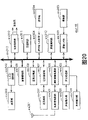
Fig. 3 is the structured flowchart that moving picture encoding device one embodiment of motion image encoding method of the present invention is used in expression.
Moving picture encoding device possesses as shown in Figure 3: replace with memory 101, calculus of differences portion 102, coded prediction error portion 103, sign indicating number column-generation portion 104, predicated error lsb decoder 105, addition operation division 106, with reference to picture with memory 107, motion vector detection section 108, mode selection part 109, coding control part 110, switch 111-115 and motion vector storage part 116.
Replace with memory 101 storages by showing the dynamic image of time sequencing with the input of picture unit.Coding control part 110 is replaced by coded sequence and is stored in each picture of replacing with in the memory 101.In addition, coding control part 110 controlled motion vectors are to the storage action of motion vector storage part 116.
The decode image data that motion vector detection section 108 will have been encoded detects the motion vector that expression is predicted as the optimum position as with reference to picture in the region of search in this picture.Mode selection part 109 uses motion vector detection section 108 detected motion vectors, determines the macroblock encoding pattern, according to this coding mode generation forecast view data.Calculus of differences portion 102 calculates from replacing poor with the view data of reading the memory 101 and the predicted image data of importing from mode selection part 109, generation forecast error image data.
The prediction error image data of 103 pairs of inputs of coded prediction error portion are carried out encoding process such as frequency translation or quantification, generate coded data.The coded data of sign indicating number column-generation portion 104 pairs of inputs is carried out Variable Length Code etc., and the information of the information by additional motion vector from mode selection part 109 inputs, coding mode and other related information etc., the generated code row.
The coded data of 105 pairs of inputs of predicated error lsb decoder is gone decoding processing such as quantification or frequency inverse conversion, generates the decoding difference image data.Addition operation division 106 will generate decode image data from the decoded difference image data of predicated error lsb decoder 105 inputs and the predicted image data addition of importing from mode selection part 109.With reference to the decode image data of picture with memory 107 storage generations.
Fig. 4 is a picture and the key diagram of relative pointer.Relatively pointer be used for unique identification with reference to picture with memory 107 storages with reference to picture, as shown in Figure 4, be that correspondence is additional to the sequence number on each picture.Use when in addition, relatively pointer is used to indicate by the inter-picture prediction encoding block with reference to picture.
Fig. 5 is based on the schematic diagram of the moving picture encoding signal format of moving picture encoding device.The code signal Picture of 1 picture unit is by the header encoder signal Header that comprises in the picture beginning, based on the code signal Block1 of the piece of Direct Model, constitute based on the code signal Block2 of the piece of the outer inter-picture prediction of Direct Model etc.In addition, the code signal Block2 based on the piece of the outer inter-picture prediction of Direct Model has two the relative pointer Rldx2 with the 2nd of the 1st relative pointer Rldx1, the 1st motion vector MV1, the 2nd motion vector MV2 that use with reference to picture that use in the expression inter-picture prediction in proper order.On the other hand, the code signal Block1 based on Direct Model does not have the 1st relative pointer Rldx1, the 2nd relative pointer Rldx2, the 1st motion vector MV1, the 2nd motion vector MV2.Can judge by types of forecast PredType and use which of the 1st relative pointer Rldx1, the 2nd relative pointer Rldx2.In addition, the 1st relative pointer Rldx1 represents the 1st with reference to picture, and the 2nd relative pointer Rldx2 represents the 2nd with reference to picture.That is be the 1st to determine by the Data Position in the sign indicating number row with reference to picture, with reference to picture or the 2nd.
Is the P picture based on the picture that one of will show before or after being positioned in the time sequencing, encoded as the 1st picture that the inter-picture prediction coding is carried out in unidirectional reference with reference to picture, is B picture as the 1st with reference to picture and the 2nd picture that carries out the inter-picture prediction coding with reference to the two-way reference of picture based on the picture that one of will show before or after being positioned in the time sequencing, encoded, but in the present embodiment, with the 1st with reference to picture as forward direction with reference to picture, with the 2nd with reference to picture as the back describe to the reference picture.In addition, will be as the relative the 1st describing as forward motion vector, backward motion vector respectively respectively with reference to picture and the 2nd the 1st motion vector, the 2nd motion vector with reference to the motion vector of picture.
Below, the addition method of the 1st relative pointer, the 2nd relative pointer is described with Fig. 4 (a).
In the 1st relative pointer, at first with regard to the information of expression DISPLAY ORDER, to before the coded object piece with reference to picture, by near the order assignment of the coded object picture value since 0.To distributing value with reference to picture before all coded objects since 0, then, to the coded object piece later with reference to picture, press order assignment value subsequently near the coded object picture.
In the 2nd relative pointer, at first with regard to the information of expression DISPLAY ORDER, to the coded object piece later with reference to picture, by near the order assignment of the coded object picture value since 0.To all coded objects later distribute value with reference to picture since 0, then, to before the coded object piece with reference to picture, press order assignment value subsequently near the coded object picture.
For example, among Fig. 4 (a), be that the 0, the 2nd relative pointer Rldx2 is that forward direction is that picture sequence numbers is 6 B picture with reference to picture under 1 the situation at the 1st relative pointer Rldx1, the back is that picture sequence numbers is 9 P picture to the reference picture.Here, picture sequence numbers is the sequence number of expression DISPLAY ORDER.
Relative pointer in the piece is showed by the variable length code word, is worth more for a short time, then distributes the short more code of code length.Usually, select apart from the nearest picture of coded object picture as inter-picture prediction with reference to picture, so if as mentioned above by apart from the relative pointer value of the near order assignment of coded object picture, then code efficiency improves.
On the other hand, by expressing indication, can change arbitrarily with reference to the distribution of picture to relative pointer with the buffer control signal in the code signal (RPSL in the Header shown in Figure 5).By this distributing altering, the 2nd relative pointer can be become 0 become with reference to picture any with in the memory 107 with reference to picture with reference to picture, for example, and shown in Fig. 4 (b), the distribution of the relative picture of variable relative pointer.
Below, the action of the moving picture encoding device of above-mentioned formation is described.
Fig. 6 is that the key diagram with the picture sequence in the memory 101 is replaced in expression, (a) is the key diagram of expression input sequence, (b) is the key diagram of expression replacement order.Wherein, vertical line is represented picture, and in the mark, the α head of the 1st literal is represented picture/mb-type (I, P or B) shown in each picture bottom right, the numeral picture sequence numbers that the 2nd literal is later, and this picture sequence numbers is represented DISPLAY ORDER.
Input picture for example shown in Fig. 6 (a), is used memory 101 by showing that time sequencing is replaced with the input of picture unit.If to replacing with memory 101 input pictures, the control part 110 of then encoding will be imported each picture of replacing with in the memory 101 and replace to the order of encoding.Carry out replacement according to the reference relation in the inter-picture prediction coding, be replaced, be encoded earlier as before the picture with reference to picture making it as picture with reference to picture to coded sequence.
Here, establish the P picture and show near I that has encoded or the P picture that is positioned at the place ahead or rear on the time sequencing with reference to 1.In addition, establish the B picture and show near the picture of having encoded that is positioned at the place ahead or rear on the time sequencing with reference to two.
The coded sequence of picture begins coding in the B picture between two P pictures (being 3 in the example of Fig. 6 (a)) from the picture that is positioned at central authorities, afterwards, the B picture near the P picture is encoded.For example, for picture B6-P9, encode by the order of picture P9, B7, B6, B8.
At this moment, in each picture of picture B6-P9, the picture of the terminal point picture reference arrow starting point of arrow shown in Fig. 6 (a).That is, picture B7 is with reference to picture P5, P9, and picture B6 is with reference to picture P5, B7, and picture B8 is with reference to picture B7, P9.In addition, at this moment, coding control part 110 replaces to each picture the order of encoding shown in Fig. 6 (b).
Below, read by motion compensation unit and to replace with each picture after replacing in the memory 101.Wherein, motion compensation unit is called macro block, macro block is made as the size of level 16 * vertical 16 pixels.Below, the encoding process of picture P9, B7, B6, B8 shown in the order key diagram 6 (a).
(encoding process of picture P9)
Picture P9 is the P picture, so with reference to showing that 1 picture having handled that is positioned at the place ahead or rear on the time sequencing carries out the inter-picture prediction coding.In the coding of picture P9, as mentioned above, become picture P5 with reference to picture.After picture P5 coding stops, decoded picture is stored in reference to picture with in the memory 107.In the coding of P picture, coding control part 110 each switch of control make switch 113,114,115 become conducting.Thereby, at first be transfused to motion vector detection section 108, mode selection part 109 and calculus of differences portion 102 from the macro block of replacing with the picture P9 that reads the memory 101.
Motion vector detection section 108 is used as with reference to picture with reference to the decode image data of picture with the picture P5 of storage in the memory 107, to the macro block detection motion vector of picture P9.In addition, motion vector detection section 108 is to the detected motion vector of mode selection part 109 outputs.
Mode selection part 109 uses motion vector detection section 108 detected motion vectors, determines the macroblock encoding pattern of picture P9.Here, so-called coding mode is that expression comes coded macroblocks with which kind of method.Under the situation of P picture, for example the inter-picture prediction of coding, use motion vector is encoded, is not used the inter-picture prediction coding of motion vector (will move and be treated to 0) in picture, determines someways to encode.In coding mode is determined, the general method of selecting further to reduce encoding error by few bit quantity.
The coding mode that mode selection part 109 is determined to 104 outputs of sign indicating number column-generation portion.At this moment, when the coding mode that mode selection part 109 is determined is the inter-picture prediction coding, the motion vector that in this inter-picture prediction coding of sign indicating number column-generation portion 104 outputs, uses, and be stored in the motion vector storage part 116.
Mode selection part 109 is according to the coding mode generation forecast view data of determining, and this predicted image data is outputed to calculus of differences portion 102 and addition operation division 106.But under the situation that mode selection part 109 is selected to encode in the picture, not prediction of output view data.In addition, under the situation that mode selection part 109 is encoded in selecting picture, control switch 111 is connected to a side, and control switch 112 is connected to the c side, and when selecting the inter-picture prediction coding, control switch 111 is connected to the b side, and control switch 112 is connected to the d side.Below, the situation of being selected the inter-picture prediction coding by mode selection part 109 is described.
The view data of the macro block of the picture P9 that from replace, reads to calculus of differences portion 102 input and the predicted image data of exporting from mode selection part 109 with memory 101.The view data of the macro block of the 102 computing picture P9 of calculus of differences portion and predicted image data poor, the generation forecast view data outputs to coded prediction error portion 103.
Coded prediction error portion 103 implements encoding process such as frequency translation or quantification by the prediction error image data to input, generates coded data, and outputs to yard column-generation portion 104 and predicated error lsb decoder 105.Wherein, establishing frequency translation or quantification treatment for example carries out with level 8 * vertical 8 pixels or level 4 * vertical 4 pixel units.
The coded data of sign indicating number column-generation portion 104 pairs of inputs is implemented Variable Length Code etc., and by information such as additional movement vector or coding mode or header etc., the generated code row are also exported.
On the other hand, the coded data of 105 pairs of inputs of predicated error lsb decoder implements to go decoding processing such as quantification or frequency inverse conversion, and after generating the decoding difference image data, outputs to addition operation division 106.Addition operation division 106 generates decode image data by with decoded difference image data and the predicted image data addition of importing from mode selection part 109, and is stored in reference to picture with in the memory 107.
By above processing, finish the processing of 1 macro block of picture P9.By same processing, all the other macro blocks of picture P9 are also carried out encoding process.In addition, as if all macro block end process, then then carry out the encoding process of picture B7 to picture P9.
(encoding process of picture B7)
Picture B7 with reference in the image, forward direction is picture P5 with reference to picture, the back is P9 to the reference picture.Because picture B7 is used as with reference to picture when other coding of graphics, so coding control part 110 each switch of control make switch 113,114,115 become conducting.Thereby, be transfused to motion vector detection section 108, mode selection part 109 and calculus of differences portion 102 from the macro block of replacing with the picture B7 that reads the memory 101.
Motion vector detection section 108 uses the decode image data of the picture P5 of storage in the memory 107 to be used as forward direction with reference to picture with reference to picture, the decode image data of picture P9 is used as the back to the reference picture, to macro block detection forward motion vector and the backward motion vector of picture B7.In addition, motion vector detection section 108 is to the detected motion vector of mode selection part 109 outputs.
Mode selection part 109 uses motion vector detection section 108 detected motion vectors, determines the macro-block coding pattern of picture B7.Here, the coding mode of B picture can be selected coding, the inter-picture prediction coding that uses forward motion vector, the inter-picture prediction coding that uses backward motion vector, the inter-picture prediction coding that uses bi-directional motion vector, the Direct Model in picture for example.
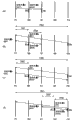
With Fig. 7 (a) action when encoding with Direct Model is described.Fig. 7 (a) is the key diagram of motion vector under the expression Direct Model, is illustrated in the situation of the piece a of encoded picture B7 under the Direct Model.The motion vector c that uses when under this situation, utilize among the encoded picture P9, the position is identical with piece a piece b, picture P9 as be positioned at after the picture B7 with reference to picture.Motion vector c is stored in the motion vector storage part 116.Piece a uses the motion vector that utilizes motion vector c to obtain, and according to as the picture P5 and picture P9 from conduct back to reference picture of forward direction with reference to picture, carries out bi-directional predicted.For example, as the method for utilizing motion vector c, the method that generates the vector that is parallel to motion vector c is arranged.Used motion vector becomes motion vector d for picture P5 during the piece a of coding this moment, becomes motion vector e for picture P9.
At this moment, if the size of establishing as the motion vector d of forward motion vector is MVF, if the size as the motion vector e of backward motion vector is MVB, the size of motion vector c is MV, the back of photo current (picture B7) is TRD to reference picture (picture P9) with the time gap to the picture (picture P5) of the piece institute reference of reference picture thereafter, photo current (picture B7) and forward direction are TRF with reference to the time gap of picture (picture P5), and then the big or small MVB of the big or small MVF of motion vector d, motion vector e is obtained by (formula 1), (formula 2) respectively.In addition, can determine the time gap between each picture according to information or this information gap of the expression DISPLAY ORDER (position) that for example is additional to each picture.
MVF=MV * TRF/TRD formula 1
MVB=(TRF-TRD) * MV/TRD formula 2
Wherein, MVF, MVB show the horizontal composition of motion vector, vertical composition respectively, and sign symbol is represented the direction of motion vector.
In the selection of coding mode, select further to reduce the method for encoding error usually by few bit quantity.The coding mode that mode selection part 109 is determined to 104 outputs of sign indicating number column-generation portion.At this moment, when the coding mode that mode selection part 109 is determined is the inter-picture prediction coding, the motion vector that in this inter-picture prediction coding of sign indicating number column-generation portion 104 outputs, uses, and be stored in the motion vector storage part 116.In addition, selecting under the situation of Direct Model, will calculate the motion vector that obtain, use in the Direct Model by (formula 1), (formula 2) and be stored in the motion vector storage part 116.
Mode selection part 109 is according to the coding mode generation forecast view data of determining, and this predicted image data is outputed to calculus of differences portion 102 and addition operation division 106.But under the situation that mode selection part 109 is selected to encode in the picture, not prediction of output view data.In addition, under the situation that mode selection part 109 is encoded in selecting picture, control switch 111 is connected to a side, control switch 112 is connected to the c side, and when selecting inter-picture prediction coding or Direct Model, control switch 111 is connected to the b side, and control switch 112 is connected to the d side.Below, the situation of being selected inter-picture prediction coding or Direct Model by mode selection part 109 is described.
The view data of the macro block of the picture B7 that from replace, reads to calculus of differences portion 102 input and the predicted image data of exporting from mode selection part 109 with memory 101.The view data of the macro block of the 102 computing picture B7 of calculus of differences portion and predicted image data poor, the generation forecast view data outputs to coded prediction error portion 103.
Coded prediction error portion 103 implements encoding process such as frequency translation or quantification by the prediction error image data to input, generates coded data, and outputs to yard column-generation portion 104 and predicated error lsb decoder 105.
The coded data of 104 pairs of inputs of sign indicating number column-generation portion is implemented Variable Length Code etc., and by information such as additional movement vector or coding modes, generated code row and output.
On the other hand, the coded data of 105 pairs of inputs of predicated error lsb decoder implements to go decoding processing such as quantification or frequency inverse conversion, and after generating the decoding difference image data, outputs to addition operation division 106.Addition operation division 106 generates decode image data by with decoded difference image data and the predicted image data addition of importing from mode selection part 109, and is stored in reference to picture with in the memory 107.
By above processing, finish the processing of 1 macro block of picture B7.By same processing, all the other macro blocks of picture B7 are also carried out encoding process.In addition, as if all macro block end process, then then carry out the encoding process of picture B6 to picture B7.
(encoding process of picture B6)
Because picture B6 is the B picture, so with reference to showing that two pictures having handled that are positioned at the place ahead or rear on the time sequencing carry out the inter-picture prediction coding.As mentioned above, picture B6 with reference in the image, forward direction is picture P5 with reference to picture, the back is B7 to the reference picture.When carrying out the coding of other picture, picture B6 is not used as with reference to picture.Thereby coding control part 110 each switch of control make switch 113 conductings, and switch 114,115 ends.Thus, be transfused to motion vector detection section 108, mode selection part 109 and calculus of differences portion 102 from the macro block of replacing with the picture B6 that reads the memory 101.
Motion vector detection section 108 uses the decode image data of the picture P5 of storage in the memory 107 to be used as forward direction with reference to picture with reference to picture, the decode image data of picture B7 is used as the back to the reference picture, to macro block detection forward motion vector and the backward motion vector of picture B6.In addition, motion vector detection section 108 is to the detected motion vector of mode selection part 109 outputs.
Mode selection part 109 uses motion vector detection section 108 detected motion vectors, determines the macro-block coding pattern of picture B6.
Here, with Fig. 7 (b) first example of moving when the macro block of picture B6 used Direct Model is described.Fig. 7 (b) is the key diagram of motion vector under the expression Direct Model, is illustrated in the situation of the piece a of encoded picture B6 under the Direct Model.At this moment, the motion vector c that uses when utilize among the encoded picture B7, the position is identical with piece a piece b, picture B7 as be positioned at after the picture B6 with reference to picture.If piece b only encodes by the forward direction reference or by two-way reference, establishing this forward motion vector is motion vector c.If motion vector c is stored in the motion vector storage part 116.Piece a uses the motion vector that utilizes motion vector c to generate, and according to as the picture P5 and picture B7 from conduct back to reference picture of forward direction with reference to picture, carries out bi-directional predicted.For example, if the same with the situation of above-mentioned picture B7, use the method that generates the motion vector that is parallel to motion vector c, then used motion vector becomes motion vector d for picture P5 during encoding block a, becomes motion vector e for picture B7.
At this moment, if the size of establishing as the motion vector d of forward motion vector is MVF, if the size as the motion vector e of backward motion vector is MVB, the size of motion vector c is MV, the back of photo current (picture B6) is TRD to reference picture (picture B7) with the time gap to the picture (picture P5) of the piece B of reference picture institute reference thereafter, photo current (picture B6) and forward direction are TRF with reference to the time gap of picture (picture P5), and then the big or small MVB of the big or small MVF of motion vector d, motion vector e is obtained by above-mentioned (formula 1), (formula 2) respectively.In addition, can determine the time gap between each picture according to information or this information gap of the expression DISPLAY ORDER that for example is additional to each picture.
Like this, under Direct Model,, needn't send the information of motion vector, and can improve action prediction efficient by to converting as the forward motion vector of back to the B of reference picture picture.Thus, can improve code efficiency.And, by with available in showing time sequencing nearest with reference to picture as forward direction with reference to picture and back to the reference picture, can improve code efficiency.
Below, second example when the use Direct Model being described with Fig. 7 (b).At this moment, the motion vector that uses when utilize among the encoded picture B7, the position is identical with piece a piece b, picture B7 as be positioned at after the picture B6 with reference to picture.At this, piece b is encoded by Direct Model, establishes the forward motion vector of using in fact this moment and is motion vector c.That is, motion vector c be by convert (ス ケ-リ Application グ) behind the picture B7 in the picture P9 of reference, the motion vector that obtains of the motion vector that uses when being in the piece i coding with piece b same position.Motion vector c uses the motion vector of storage in the motion vector storage part 116, or behind the motion vector of the piece i in the picture P9 that uses when reading by Direct Model encoding block b from motion vector storage part 116, calculating is obtained.Mode selection part 109 also can be by the piece b of Direct Model encoded picture B7 the time be handled the motion vector of obtaining and is stored under the situation in the motion vector storage part 116 by converting, only store forward motion vector.Piece a uses the motion vector that utilizes motion vector c to generate, and according to as the picture P5 and picture B7 from conduct back to reference picture of forward direction with reference to picture, carries out bi-directional predicted.For example, if the same with the situation of above-mentioned first example, use the method that generates the motion vector that is parallel to motion vector c, then used motion vector becomes motion vector d for picture P5 during encoding block a, becomes motion vector e for picture B7.
At this moment, as to the big or small MVF of the motion vector d of the forward motion vector of piece a, with the same, can use (formula 1), (formula 2) to obtain as first example of the big or small MVB of the motion vector e of backward motion vector and Direct Model.
Like this, under Direct Model, to converting to the forward motion vector that the B of reference picture picture uses in fact under Direct Model as the back, so needn't send the information of motion vector, and, even under Direct Model, during the piece of coding back same position in the reference picture, also can improve action prediction efficient.Thus, can improve code efficiency.And, by will be in showing time sequencing available nearest with reference to picture as forward direction and back to the reference picture, can improve code efficiency.
Below, the 3rd example when illustrating with Direct Model with Fig. 7 (c).Fig. 7 (c) is the key diagram of motion vector under the expression Direct Model, is illustrated in the situation of the piece a of encoded picture B6 under the Direct Model.The motion vector c that uses when under this situation, utilize among the encoded picture B7, the position is identical with piece a piece b, picture B7 as be positioned at after the picture B6 with reference to picture.Wherein, establish and only use backward motion vector to come encoding block b, and to establish this backward motion vector be motion vector f.If motion vector f is stored in the motion vector storage part 116.Piece a uses the motion vector that utilizes motion vector f to generate, and according to as the picture P5 and picture B7 from conduct back to reference picture of forward direction with reference to picture, carries out bi-directional predicted.For example, if the same method that generates the motion vector that is parallel to motion vector f of using with the situation of above-mentioned first example, then used motion vector becomes motion vector g for picture P5 during encoding block a, becomes motion vector h for picture B7.
At this moment, if the size of establishing as the motion vector g of forward motion vector is MVF, if the size as the motion vector h of backward motion vector is MVB, the size of motion vector f is MV, the back of photo current (picture B6) is TRD to reference picture (picture B7) with the time gap to the picture (picture P9) of the piece institute reference of reference picture thereafter, photo current (picture B6) and forward direction are TRF with reference to the time gap of picture (picture P5), photo current (picture B6) is TRB with the back to the time gap of reference picture (picture B7), then the big or small MVF of motion vector g, the big or small MVB of motion vector h is respectively by (formula 3), (formula 4) obtained.
MVF=-TRF * MV/TRD formula 3
MVB=TRB * MV/TRD formula 4
Like this, under Direct Model, the backward motion vector that coding is used during the piece on the same position in the B of reference picture picture as the back converts, so needn't send the information of motion vector, and, even when the piece on the same position of back in the reference picture only has backward motion vector, also can improve forecasting efficiency.Thus, can improve code efficiency.And, by will be in showing time sequencing available nearest with reference to picture as forward direction and back to the reference picture, can improve code efficiency.
Below, the 4th example when the use Direct Model being described with Fig. 7 (d).Fig. 7 (d) is the key diagram of motion vector under the expression Direct Model, is illustrated in the situation of the piece a of encoded picture B6 under the Direct Model.At this moment, the motion vector that uses when utilize among the encoded picture B7, the position is identical with piece a piece b, picture B7 as be positioned at after the picture B6 with reference to picture.If the same with the 3rd example, only use backward motion vector to come encoding block b, establishing this backward motion vector is motion vector f.If motion vector f is stored in the motion vector storage part 116.Piece a uses the motion vector that utilizes motion vector f to generate, and according to as the picture P9 and picture B7 from conduct back to reference picture of motion vector f with reference to picture, carries out bi-directional predicted.For example, if the same with the situation of above-mentioned first example, use the method that generates the motion vector that is parallel to motion vector f, then used motion vector becomes motion vector g for picture P9 during encoding block a, becomes motion vector h for picture B7.
At this moment, if the size of establishing as the motion vector g of forward motion vector is MVF, if the size as the motion vector h of backward motion vector is MVB, the size of motion vector f is MV, the back of photo current (picture B6) is TRD to reference picture (picture B7) with the time gap to the picture (picture P9) of the piece institute reference of reference picture thereafter, photo current (picture B6) is TRF with the back to the time gap of the picture (picture P9) of the piece institute reference of reference picture (picture B7), then the big or small MVF of motion vector g, the big or small MVB of motion vector h is respectively by (formula 1), (formula 2) obtained.
Like this, under Direct Model, the backward motion vector that coding is used during the piece of same position in the B of reference picture picture as the back converts, thereby needn't send the information of motion vector, and, even the piece of same position in the reference picture only has under the situation of backward motion vector in the back, also can improve forecasting efficiency.Thus, can improve code efficiency.And, by with the picture of backward motion vector institute reference as forward direction with reference to picture, will be in showing time sequencing available nearest with reference to picture as the back to the reference picture, can improve code efficiency.
Below, the 5th example when illustrating with Direct Model with Fig. 8 (a).Fig. 8 (a) is the key diagram of motion vector under the expression Direct Model, is illustrated in the situation of the piece a of encoded picture B6 under the Direct Model.Under this situation, with the size of motion vector as 0, with picture P5 as forward direction with reference to picture, with picture B7 as the back to the reference picture, by carrying out two-way reference, carry out motion compensation.
Like this, under Direct Model, force to be set to 0, under the situation of selecting Direct Model, can send the information of motion vector, and needn't can cut down treating capacity the motion vector processing that converts by motion vector.
Below, the 6th example when illustrating with Direct Model with Fig. 8 (b).Fig. 8 (b) is the key diagram of motion vector under the expression Direct Model, is illustrated in the situation of the piece a of encoded picture B6 under the Direct Model.At this moment, the motion vector g that uses when utilize among the encoded picture P9, the position is identical with piece a piece f, picture P9 is as the P picture that is positioned at after the picture B6.Motion vector g is stored in the motion vector storage part 116.Piece a uses the motion vector that utilizes motion vector g to generate, and according to as the picture P5 and picture B7 from conduct back to reference picture of forward direction with reference to picture, carries out bi-directional predicted.For example, if the same method that generates the motion vector that is parallel to motion vector g of using with the situation of above-mentioned first example, then used motion vector becomes motion vector h for picture P5 during encoding block a, becomes motion vector i for picture B7.
At this moment, if the size of establishing as the motion vector h of forward motion vector is MVF, if the size as the motion vector i of backward motion vector is MVB, the size of motion vector g is MV, the time gap that shows the picture (picture P5) of the piece f institute reference that is positioned at photo current (picture B6) P picture (picture P9) afterwards and this P picture on the time sequencing is TRD, photo current (picture B6) and forward direction are TRF with reference to the time gap of picture (picture P5), photo current (picture B6) is TRB with the back to the time gap of reference picture (picture B7), then the big or small MVF of motion vector h, the big or small MVB of motion vector i is respectively by (formula 1), (formula 5) obtained.
MVB=-TRB * MV/TRD formula 5
Like this, under Direct Model, converting to showing the motion vector that is positioned at the P picture at rear on the time sequencing, is under the situation of B picture in the back to the reference picture, needn't store the motion vector of this B picture, and needn't send the information of motion vector.And, by will be in showing time sequencing nearest with reference to picture as forward direction and back to the reference picture, can improve code efficiency.
Below, the 7th example when the use Direct Model being described with Fig. 8 (c).Fig. 8 (c) is the key diagram of motion vector under the expression Direct Model, is illustrated in the situation of the piece a of encoded picture B6 under the Direct Model.This example is picture sequence numbers change (mapping again) distribution of pointer relatively to above-mentioned explanation, and the back becomes the situation of picture P9 to the reference picture.At this moment, the motion vector g that uses when utilize among the encoded picture P9, the position is identical with piece a piece f, picture P9 is back to the reference picture as picture B7's.Motion vector g is stored in the motion vector storage part 116.Piece a uses the motion vector that utilizes motion vector g to generate, and according to as the picture P5 and picture P9 from conduct back to reference picture of forward direction with reference to picture, carries out bi-directional predicted.For example, if the same with the situation of above-mentioned first example, use the method that generates the motion vector that is parallel to motion vector g, then used motion vector becomes motion vector h for picture P5 during encoding block a, becomes motion vector i for picture P9.
At this moment, if the size of establishing as the motion vector h of forward motion vector is MVF, if the size as the motion vector i of backward motion vector is MVB, the size of motion vector g is MV, the back of photo current (picture B6) is TRD to reference picture (picture P9) with the time gap to the picture (picture P5) of the piece institute reference of reference picture thereafter, photo current (picture B6) and forward direction are TRF with reference to the time gap of picture (picture P5), and then the big or small MVB of the big or small MVF of motion vector h, motion vector i is obtained by (formula 1), (formula 2) respectively.
Like this, under Direct Model, even in the branch timing of picture sequence numbers being changed relative pointer, also can the motion vector of the picture of having encoded be converted, and under the situation of selecting Direct Model, needn't send the information of motion vector.
In addition, by the piece a of Direct Model encoded picture B6 the time, only by forward direction with reference to, two-way reference or Direct Model come encoded picture B6 back in the reference picture position piece identical with piece a, when coding, use under the situation of forward motion vector, this forward motion vector is converted, as above-mentioned first example, second example or the 7th example, by Direct Model encoding block a.On the other hand, only come the coding site piece identical to reference, when coding, use under the situation of backward motion vector, this backward motion vector is converted, as above-mentioned the 3rd example or the 4th example, by Direct Model encoding block a with piece a by the back.
Above-mentioned Direct Model is not only applicable to constant situation of the time interval of interframe, also applicable to the situation of variable frame period.
The coding mode that mode selection part 109 is determined to 104 outputs of sign indicating number column-generation portion.In addition, mode selection part 109 is according to the coding mode of determining, the generation forecast view data, and this predicted image data outputed to calculus of differences portion 102.But under the situation that mode selection part 109 is encoded in selecting picture, not prediction of output view data.In addition, under the situation that mode selection part 109 is encoded in selecting picture, control switch 111 is connected to a side, control switch 112 is connected to the c side, and when selecting inter-picture prediction coding or Direct Model, control switch 111 is connected to the b side, and control switch 112 is connected to the d side.In addition, mode selection part 109 is under the situation of inter-picture prediction coding at the coding mode of determining, the motion vector that uses in this inter-picture prediction coding of sign indicating number column-generation portion 104 outputs.Here, because picture B6 is not used as with reference to picture when other picture of coding, so the motion vector that uses in the inter-picture prediction coding needn't be stored in the motion vector storage part 116.Below, the situation of being selected inter-picture prediction coding or Direct Model by mode selection part 109 is described.
The view data of the macro block of the picture B6 that from replace, reads to calculus of differences portion 102 input and the predicted image data of exporting from mode selection part 109 with memory 101.The view data of the macro block of the 102 computing picture B6 of calculus of differences portion and predicted image data poor, generation forecast error image data output to coded prediction error portion 103.Coded prediction error portion 103 implements encoding process such as frequency translation or quantification by the prediction error image data to input, generates coded data, and outputs to a yard column-generation portion 104.
The coded data of 104 pairs of inputs of sign indicating number column-generation portion is implemented Variable Length Code etc., and by information such as additional movement vector or coding modes, generated code row and output.
By above processing, finish 1 macroblock encoding of picture B6 and handle.Also handle equally by all the other macro blocks,, then carry out the encoding process of picture B8 in case finish processing to picture B6.
(encoding process of picture B8)
Because picture B8 is the B picture, so with reference to showing that two pictures having handled that are positioned at the place ahead or rear on the time sequencing carry out the inter-picture prediction coding.As mentioned above, picture B8 with reference in the image, forward direction is picture B7 with reference to picture, the back is P9 to the reference picture.When carrying out the coding of other picture, picture B8 is not used as with reference to picture, thereby coding control part 110 each switch of control make switch 113 conductings, and switch 114,115 ends.Thus, from replacing with the picture of reading the memory 101,8 macro block is transfused to motion vector detection section 108, mode selection part 109 and calculus of differences portion 102.
Motion vector detection section 108 uses the decode image data of the picture B7 of storage in the memory 107 to be used as forward direction with reference to picture with reference to picture, the decode image data of picture P9 is used as the back to the reference picture, to macro block detection forward motion vector and the backward motion vector of picture B8.In addition, motion vector detection section 108 is to the detected motion vector of mode selection part 109 outputs.
Mode selection part 109 uses motion vector detection section 108 detected motion vectors, determines the macro-block coding pattern of picture B8.
Here, with Fig. 8 (d) action when the macro block of picture B8 used Direct Model is described.Fig. 8 (d) is the key diagram of motion vector under the expression Direct Model, is illustrated in the situation of the piece a of encoded picture B8 under the Direct Model.At this moment, the motion vector that uses when utilize among the encoded picture P9, the position is identical with piece a piece b, picture P9 as be positioned at after the picture B8 with reference to picture.If piece b is only encoded by the forward direction reference, establishing this forward motion vector is motion vector c.If motion vector c is stored in the motion vector storage part 116.Piece a uses the motion vector that utilizes motion vector c to generate, and according to as the picture B7 and picture P9 from conduct back to reference picture of forward direction with reference to picture, carries out bi-directional predicted.For example, if the same with the situation of above-mentioned picture B7, use the method that generates the motion vector that is parallel to motion vector c, then used motion vector becomes motion vector d for picture B7 during encoding block a, becomes motion vector e for picture P9.
At this moment, if the size of establishing as the motion vector d of forward motion vector is MVF, if the size as the motion vector e of backward motion vector is MVB, the size of motion vector c is MV, the back of photo current (picture B8) is TRD to reference picture (picture P9) with the time gap to the picture (picture P5) of the piece b of reference picture institute reference thereafter, photo current (picture B8) and forward direction are TRF with reference to the time gap of picture (picture B7), photo current (picture B8) is TRB with the back to the time gap of reference picture (picture P9), then the big or small MVF of motion vector d, the big or small MVB of motion vector e is respectively by above-mentioned (formula 1), (formula 5) obtained.
Like this, under Direct Model,, needn't send the information of motion vector, and can improve forecasting efficiency by the forward motion vector of back to the reference picture converted.Thus, can improve code efficiency.And, by with available in showing time sequencing nearest with reference to picture as forward direction with reference to picture and back to the reference picture, can improve code efficiency.
Above-mentioned Direct Model is not only applicable to constant situation of the time interval of interframe, also applicable to the situation of variable frame period.
The coding mode that mode selection part 109 is determined to 104 outputs of sign indicating number column-generation portion.In addition, mode selection part 109 is according to the coding mode of determining, the generation forecast view data, and this predicted image data outputed to calculus of differences portion 102.But under the situation that mode selection part 109 is encoded in selecting picture, not prediction of output view data.In addition, under the situation that mode selection part 109 is encoded in selecting picture, control switch 111 is connected to a side, control switch 112 is connected to the c side, and when selecting inter-picture prediction coding or Direct Model, control switch 111 is connected to the b side, and control switch 112 is connected to the d side.In addition, mode selection part 109 is under the situation of inter-picture prediction coding at the coding mode of determining, the motion vector that uses in this inter-picture prediction coding of sign indicating number column-generation portion 104 outputs.Here, because picture B8 is not used as with reference to picture when other picture of coding, so the motion vector that uses in the inter-picture prediction coding needn't be stored in the motion vector storage part 116.Below, the situation of being selected inter-picture prediction coding or Direct Model by mode selection part 109 is described.
The view data of the macro block of the picture B8 that from replace, reads to calculus of differences portion 102 input and the predicted image data of exporting from mode selection part 109 with memory 101.The view data of the macro block of the 102 computing picture B8 of calculus of differences portion and predicted image data poor, generation forecast error image data output to coded prediction error portion 103.Coded prediction error portion 103 implements encoding process such as frequency translation or quantification by the prediction error image data to input, generates coded data, and outputs to a yard column-generation portion 104.
The coded data of 104 pairs of inputs of sign indicating number column-generation portion is implemented Variable Length Code etc., and by information such as additional movement vector or coding modes, generated code row and output.
By above processing, finish 1 macroblock encoding of picture B8 is handled.All the other macro blocks to picture B8 are also handled equally.
Below, showing the coding method of time sequencing position corresponding to the picture kind of each picture and picture, by carrying out the encoding process of each picture with picture P9, B7, method that B6, B8 are the same.
In above embodiment, be example with the situation of using picture predict shown in Fig. 6 (a), the action of motion image encoding method of the present invention is described.Figure 12 is the key diagram of layer representation picture predict at this moment.Among Figure 12, arrow is represented projected relationship, and expression is positioned at the picture of arrow terminal point with reference to the picture that is positioned at starting point.In picture predict shown in Fig. 6 (a),, as shown in figure 12, preferentially determine coded sequence apart from the picture picture farthest of having encoded by showing under the situation that time sequencing is considered.For example, be the picture that is positioned at continuous B picture central authorities apart from I or P picture picture farthest.Therefore, under the state that for example picture P5, P9 have encoded, picture B7 becomes next coded object picture.Under the state that picture P5, B7, P9 have encoded, picture B6, B8 become next coded object picture.
In addition, even under Fig. 6, the situation with different picture predict shown in Figure 12, also can use the method the same, can realize effect of the present invention with motion image encoding method of the present invention.Fig. 9-Figure 11 illustrates other picture predict example.
The number that Fig. 9 represents to be clipped in the B picture between I or P picture is 3, as the order of coding B picture, from the situation that begins apart from the nearest picture of picture of having encoded to select to encode.Fig. 9 (a) is the projected relationship figure that represents by showing each picture that time sequencing is represented, Fig. 9 (b) is the figure that expression replaces to the picture sequence of coded sequence (sign indicating number row order).Figure 13 is the hierarchical diagram corresponding to the picture predict of Fig. 9 (a).In picture predict shown in Fig. 9 (a), under by the situation that shows the time sequencing consideration, as shown in figure 13, from beginning sequential encoding apart from the nearest picture of picture of having encoded.For example, under the state that picture P5, P9 have encoded, picture B6, B8 become next coded object picture.Under the state that picture P5, B6, B8, P9 have encoded, picture B7 becomes next coded object picture.
The number that Figure 10 represents to be clipped in the B picture between I or P picture is 5, in the priority encoding B picture apart from the situation of the picture picture farthest of having encoded.Figure 10 (a) is the projected relationship figure that represents by showing each picture that time sequencing is represented, Figure 10 (b) is the figure that expression replaces to the picture sequence of coded sequence (sign indicating number row order).Figure 14 is the hierarchical diagram corresponding to the picture predict of Figure 10 (a).In picture predict shown in Figure 10 (a), preferential apart from the picture picture farthest of having encoded as shown in figure 14 by showing under the situation that time sequencing is considered, determine coded sequence.For example, be the picture that is positioned at continuous B picture central authorities apart from I or P picture picture farthest.Therefore, for example under the state that picture P7, P13 have encoded, picture B10 becomes next coded object picture.Under the state that picture P7, B10, P13 have encoded, picture B8, B9, B11, B12 become next coded object picture.
The number that Figure 11 represents to be clipped in the B picture between I or P picture is 5, in the priority encoding B picture apart from the situation of the nearest picture of the picture of having encoded.Figure 11 (a) is the projected relationship figure that represents by showing each picture that time sequencing is represented, Figure 11 (b) is the figure that expression replaces to the picture sequence of coded sequence (sign indicating number row order).Figure 15 is the hierarchical diagram corresponding to the picture predict of Figure 11 (a).In picture predict shown in Figure 11 (a), under by the situation that shows the time sequencing consideration, as shown in figure 15, from beginning sequential encoding apart from the nearest picture of picture of having encoded.For example, under the state that picture P5, P9 have encoded, picture B8, B12 become next coded object picture.Under the state that picture P5, B8, B12, P9 have encoded, picture B9, B11 become next coded object picture.And under the state that picture P5, B8, B9, B11, B12, P9 have encoded, picture B10 becomes next coded object picture.
As mentioned above, in motion image encoding method of the present invention, when using bi-directional predicted the coding during B picture that carries out the inter-picture prediction encoding process, encoding by the order different with showing time sequencing is clipped in a plurality of B pictures between I or P picture.At this moment, be positioned in nearest picture in the time sequencing as forward direction and back to the reference picture show.Under the available situation of B picture, also the B picture can be used as this with reference to picture.In addition, when being clipped in a plurality of B picture between I or P picture when encoding, from beginning sequential encoding apart from the picture picture farthest of having encoded by the order different with showing time sequencing.In addition, encoding by the order different when being clipped in a plurality of B picture between I or P picture, from beginning sequential encoding apart from the nearest picture of picture of having encoded with showing time sequencing.
By this action, use motion image encoding method of the present invention, thereby when coding B picture, can be with picture nearer in showing time sequencing as with reference to picture, and the forecasting efficiency can improve motion compensation thus the time, so can improve code efficiency.
In addition, in motion image encoding method of the present invention, with reference to the picture that is encoded to the B picture, as the back to the reference picture, and by the piece in the Direct Model coding B picture, at this moment, when the piece of the back same position in the reference picture of encoding by forward direction reference or two-way reference, will be used as the motion vector under the Direct Model by the motion vector that this forward motion vector that converts obtains.
Like this, under Direct Model,, needn't send the information of motion vector, and can improve forecasting efficiency by to converting as the forward motion vector of back to the B of reference picture picture.And, by go up service time nearest with reference to picture as forward direction with reference to picture, can improve code efficiency.
In addition, when being encoded the piece of conduct back same position in the B of reference picture picture by Direct Model, the motion vector that will obtain by the forward motion vector that essence under the conversion Direct Model is used is as the motion vector under the Direct Model.
Like this, under Direct Model, by the forward motion vector of using to the B of reference picture picture essence under Direct Model as the back is converted, needn't send the information of motion vector, and, even under Direct Model, during the piece of coding back same position in the reference picture, also can improve forecasting efficiency.And, by will the time go up nearest with reference to picture as forward direction with reference to picture, can improve code efficiency.
In addition, encoding as the back in the B of reference picture picture during the piece of same position to reference by the back, the motion vector that this backward motion vector that converts is obtained is used as the motion vector under the Direct Model.
Like this, under Direct Model, convert by the backward motion vector that coding is used during the piece of same position in the B of reference picture picture as the back, needn't send the information of motion vector, and, even the piece of same position in the reference picture only has under the situation of backward motion vector in the back, also can improve forecasting efficiency.And, by will the time go up nearest with reference to picture as forward direction with reference to picture, can improve code efficiency.
In addition, encoding as the back in the B of reference picture picture during the piece of same position to reference by the back, will be used as motion vector under the Direct Model by the picture of this backward motion vector institute reference and back are scaled with reference to picture resulting motion vector to the reference picture in the backward motion vector of using this moment.
Like this, under Direct Model, convert by the backward motion vector that coding is used during the piece of same position in the B of reference picture picture as the back, needn't send the information of motion vector, and, even the piece of same position in the reference picture only has under the situation of backward motion vector in the back, also can improve forecasting efficiency.Thus, can improve code efficiency.And, by with the picture of backward motion vector reference as forward direction with reference to picture, with show in the time sequencing available nearest with reference to picture as the back to the reference picture, can improve code efficiency.
In addition, under Direct Model, use size to be forced to be made as 0 motion vector.
Like this, force to be set to 0, under the situation of selecting Direct Model, needn't send the information of motion vector by the motion vector under the Direct Model, and, do not need the conversion of motion vector to handle, can cut down treating capacity.
In addition, in motion image encoding method of the present invention, with reference to the picture that is encoded to the B picture as the back to the reference picture, and when encoding piece in the B picture with Direct Model, the motion vector that the time forward motion vector used in the P picture after conversion is coded on the same position obtains is as the motion vector under the Direct Model.
Like this, under Direct Model,, be under the situation of B picture to the reference picture in the back by the motion vector at back P picture is converted, needn't store the motion vector of this B picture, and, needn't send the information of motion vector, can improve forecasting efficiency.And, by will the time go up nearest with reference to picture as forward direction with reference to picture, can improve code efficiency.
In addition, the distribution that picture sequence numbers is changed relative pointer, by forward direction during with reference to the piece of the back same position in the reference picture of encoding, the motion vector that this forward motion vector that converts is obtained is as the motion vector under the Direct Model.
Like this, under Direct Model,, also can the motion vector of the picture of having encoded be converted, and needn't send the information of motion vector even in the branch timing of picture sequence numbers being changed relative pointer.
In the present embodiment, illustrate with level 16 * vertical 16 pixel units and handle motion compensation, handle the situation that prediction error image is encoded, but these units also can be other number of picture elements with level 8 * vertical 8 pixel units or level 4 * vertical 4 units.
In addition, in the present embodiment, illustrate continuous B picture number and be 3 or 5 s' situation, but the number of B picture also can be other number.
In the present embodiment, the coding mode that illustrates the P picture is encoded, is used the inter-picture prediction of motion vector to encode, do not use the inter-picture prediction coding of motion vector in picture and selects, and, situation about selecting the inter-picture prediction coding of forward motion vector, the inter-picture prediction coding that uses backward motion vector, the inter-picture prediction coding that uses bi-directional motion vector, the Direct Model is encoded, used to the coding mode of B picture in picture, but these coding modes also can be other methods.
In addition, in the present embodiment, Direct Model has been illustrated 7 examples, but also can use, also can from a plurality of methods, select a method each piece or macro block to each macro block or the well-determined method of piece.Under the situation of using a plurality of methods, use the information of which Direct Model to be recorded in the sign indicating number row expression.
In addition, in the present embodiment, illustrate that the P picture shows that with reference to 1 being positioned at front or rear I that has encoded or P picture on the time sequencing encodes, the B picture is with reference to two situations that show that near the picture of having encoded before or after being positioned on the time sequencing is encoded, but at these pictures is under the situation of P picture, substitute as the reference picture showing a plurality of I pictures of having encoded or P picture before or after being positioned in the time sequencing, and encode with reference to 1 maximum in each piece picture, under the situation that is the B picture, be positioned near front or rear a plurality of pictures of having encoded in the time sequencing as reference picture substitute, and encode with reference to two maximum in each piece pictures show.
In addition, mode selection part 109 when coming the coded object piece by bi-directional predicted or Direct Model, can be stored forward direction and back to both motion vectors when motion vector being stored in the motion vector storage part 116, also can only store forward motion vector.If only store forward motion vector, the amount of memory that then can cut down motion vector storage part 116.
(embodiment 2)
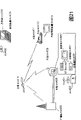
Figure 16 is the structured flowchart that dynamic image decoding device one embodiment of motion image encoding method of the present invention is used in expression.
Dynamic image decoding device possesses as shown in figure 16: sign indicating number row analysis portion 1401, predicated error lsb decoder 1402, mode decoding portion 1403, frame memory control part 1404, motion compensation decoding portion 1405, motion vector storage part 1406, frame memory 1407, addition operation division 1408 and switch 1409,1410.
Sign indicating number row analysis portion 1401 is extracted various data such as coding mode information and motion vector information out from the sign indicating number row of input.1402 decodings of predicated error lsb decoder are from the coded prediction error data of sign indicating number row analysis portion 1401 inputs, generation forecast error image data.Mode decoding portion 1403 is with reference to the coding mode information of extracting out from the sign indicating number row, control switch 1409,1410.
Frame memory control part 1404 is according to the information of the expression picture DISPLAY ORDER of importing from sign indicating number row analysis portion 1401, and the decode image data of storage in the output frame memory 1407 is as output image.
The decoding processing that motion compensation decoding portion 1405 carries out with reference to picture sequence numbers and motion vector information with reference to picture sequence numbers and motion vector, obtains motion-compensated image data from frame memory 1407 according to decoded.Motion vector storage part 1406 storing moving vectors.
Addition operation division 1408 will generate decode image data from the coded prediction error data and the motion-compensated image data addition of importing from motion compensation decoding portion 1405 of predicated error lsb decoder 1402 inputs.The decode image data that frame memory 1407 storages generate.
Below, the action of the dynamic image decoding device of above-mentioned formation is described.Here, establish to dynamic image decoding device and import the sign indicating number row that generate in the above-mentioned moving picture encoding device.That is, here, establish the P picture and show near I that has encoded or the P picture that is positioned at the place ahead or rear on the time sequencing with reference to 1.In addition, establish the B picture and show near the picture of having encoded that is positioned at the place ahead or rear on the time sequencing with reference to two.
Picture in the sign indicating number row of this moment becomes order shown in Fig. 6 (b).Below, order illustrates the decoding processing of picture P9, B7, B6, B8.
(decoding processing of picture P9)
Sign indicating number row input code row analysis portion 1401 with picture P9.Sign indicating number row analysis portion 1401 is extracted various data out from the sign indicating number row of input.Here, so-called various data are model selection information or motion vector information etc.The model selection information of extracting out is outputed to mode decoding portion 1403.In addition, the motion vector information of extracting out is outputed to motion compensation decoding portion 1405.And, the coded prediction error data are outputed to predicated error lsb decoder 1402.
Information, control switch 1409,1410 are selected with reference to the coding mode of extracting out by mode decoding portion 1403 from the sign indicating number row.Under the situation of encoding in coding mode is chosen as picture, mode decoding portion 1403 control switchs 1409 are connected to a side, and control switch 1410 is connected to the c side.In addition, when coding mode was chosen as the inter-picture prediction coding, mode decoding portion 1403 control switchs 1409 were connected to the b side, and control switch 1410 is connected to the d side.
Mode decoding portion 1403 is also to motion compensation decoding portion 1405 output encoder model selection information.Below, illustrate that coding mode is chosen as the situation of inter-picture prediction coding.The coded prediction error data of predicated error lsb decoder 1402 decoding inputs, generation forecast error image data.The prediction error image data that predicated error lsb decoder 1402 generates to switch 1409 outputs.Here, because switch 1409 is connected in the b side, so to addition operation division 1408 prediction of output error image data.
Motion compensation decoding portion 1405 obtains motion-compensated image data according to the motion vector information etc. of input from frame memory 1407.Picture P9 encodes with reference to picture P5, after picture P5 is decoded, remains in the frame memory 1407.Therefore, motion compensation decoding portion 1405 must move compensating image data according to motion vector information in the view data of the picture P5 that keeps from frame memory 1407.The motion-compensated image data that so generates is outputed to addition operation division 1408.
Motion compensation decoding portion 1405 under the situation of decoding P picture, with the information stores of motion vector in motion vector storage part 1406.
Addition operation division 1408 generates decode image data with the prediction error image data and the motion-compensated image data addition of input.The decode image data that generates outputs to frame memory 1407 through switch 1410.
As mentioned above, finish the processing of 1 macro block of picture P9.By same processing, remaining macro block of decoding in proper order.If the macro block of all picture P9 of decoding then carries out the decoding of picture B7.
(decoding processing of picture B7)
Action in sign indicating number row analysis portion 1401, mode decoding portion 1403 and the predicated error lsb decoder 1402 before the generation forecast error image data is the same during with the decoding processing of picture P9, so the omission explanation.
Motion compensation decoding portion 1405 generates motion compensation (motion compensation) view data according to the motion vector information etc. of input.Picture B7 with reference to picture P5 as forward direction with reference to picture, with reference to P9 as the back to the reference picture, encode, after these pictures are decoded, remain in the frame memory 1407.
When model selection was bi-directional predicted inter-picture prediction coding, motion compensation decoding portion 1405 obtained the forward direction reference image data according to forward motion vector information from frame memory 1407.In addition, according to backward motion vector information, from frame memory 1407, obtain the back to reference image data.Motion compensation decoding portion 1405 generates motion-compensated image data by summation averaging forward direction reference image data and back to reference image data.
In model selection is under the situation of Direct Model, and motion compensation decoding portion 1405 obtains the motion vector of the picture P9 of storage in the motion vector storage part 1406.In addition, motion compensation decoding portion 1405 uses this motion vector, obtains forward direction reference image data and back to reference image data from frame memory 1407.Motion compensation decoding portion 1405 generates motion-compensated image data by summation averaging forward direction reference image data and back to reference image data.
Also use Fig. 7 (a) to illustrate that model selection is the situation of Direct Model.Wherein, establish the piece a of decoding picture B7, and to establish the piece that is positioned at the picture P9 on the same position with piece a be piece b.In addition, the motion vector of piece b is motion vector c, and this motion vector c is with reference to picture P5.At this moment, use motion vector d to be used as forward motion vector, use motion vector e with reference to the picture P9 that utilizes motion vector c to obtain as backward motion vector with reference to the picture P5 that utilizes motion vector c to obtain.For example, as the method for utilizing motion vector c, the method that generates the motion vector that is parallel to motion vector c is arranged.If summation averaging is motion-compensated image data according to the forward direction comparable data that these motion vectors obtain with the view data of back after comparable data.
At this moment, if the size of establishing as the motion vector d of forward motion vector is MVF, if the size as the motion vector e of backward motion vector is MVB, the size of motion vector c is MV, the back of photo current (picture B7) is TRD to reference picture (picture P9) with the time gap to the picture (picture P5) of the piece b of reference picture institute reference thereafter, photo current (picture B7) and forward direction are TRF with reference to the time gap of picture (picture P5), and then the big or small MVB of the big or small MVF of motion vector d, motion vector e is obtained by (formula 1), (formula 2) respectively.Wherein, MVF, MVB show the horizontal composition of motion vector, vertical composition respectively.In addition, for example can determine time gap between each picture according to the information of the expression DISPLAY ORDER (position) that is additional to each picture or its information gap.
The motion-compensated image data that so generates is outputed to addition operation division 1408.In addition, motion compensation (motion compensation) lsb decoder 1405 is stored in motion vector information in the motion vector storage part 1406.
Addition operation division 1408 generates decode image data with the prediction error image data and the motion-compensated image data addition of input.The decode image data that generates is outputed to frame memory 1407 through switch 1410.
As mentioned above, finish the processing of 1 macro block of picture B7.By same processing, remaining macro block of decoding in proper order.If the macro block of the whole picture B7 of decoding, then decoding picture B6.
(decoding processing of picture B6)
Action in sign indicating number row analysis portion 1401, mode decoding portion 1403 and the predicated error lsb decoder 1402 before the generation forecast error image data is the same during with the decoding processing of picture P9, so the omission explanation.
Motion compensation decoding portion 1405 generates motion-compensated image data according to the motion vector information etc. of input.Picture B6 with reference to picture P5 as forward direction with reference to picture, with reference to B7 as the back to the reference picture, encode, after these pictures are decoded, remain in the frame memory 1407.
When model selection was bi-directional predicted inter-picture prediction coding, motion compensation decoding portion 1405 obtained the forward direction reference image data according to forward motion vector information from frame memory 1407.In addition, according to backward motion vector information, from frame memory 1407, obtain the back to reference image data.Motion compensation decoding portion 1405 generates motion-compensated image data by summation averaging forward direction reference image data and back to reference image data.
In model selection is under the situation of Direct Model, and motion compensation decoding portion 1405 obtains the motion vector of the picture B7 of storage in the motion vector storage part 1406.Motion compensation decoding portion 1405 uses this motion vector, obtains forward direction reference image data and back to reference image data from frame memory 1407.Motion compensation decoding portion 1405 generates motion-compensated image data by summation averaging forward direction reference image data and back to reference image data.
First example when illustrating that with Fig. 7 (b) model selection is Direct Model.Wherein, establish the piece a of decoding picture B6, and to establish the piece that is positioned at the picture B7 on the same position with piece a be piece b.In addition, establish, and the forward motion vector of establishing piece b is motion vector c based on the inter-picture prediction of forward direction reference coding or based on the inter-picture prediction encoding block b of two-way reference.This motion vector c is with reference to picture P5.At this moment, use motion vector d with reference to the picture P5 that utilizes motion vector c to generate to be used as forward motion vector, use motion vector e with reference to the picture B7 that utilizes motion vector c to generate as backward motion vector to piece a.For example, as the method for utilizing motion vector c, the method that generates the motion vector that is parallel to motion vector c is arranged.If summation averaging is the motion compensation view data according to the forward direction reference image data that these motion vectors obtain with the view data of back after reference image data.
At this moment, if the size of establishing as the motion vector d of forward motion vector is MVF, if the size as the motion vector e of backward motion vector is MVB, the size of motion vector c is MV, the back of photo current (picture B6) is TRD to reference picture (picture B7) with the time gap to the picture (picture P5) of the piece b of reference picture institute reference thereafter, photo current (picture B6) and forward direction are TRF with reference to the time gap of picture (picture P5), and then the big or small MVB of the big or small MVF of motion vector d, motion vector e is obtained by (formula 1), (formula 2) respectively.In addition, for example can determine time gap between each picture according to the information of the expression DISPLAY ORDER (position) that is additional to each picture or its information gap.In addition, the value of TRD, TRF also can be used the setting that each picture is determined.This setting also can be used as header and is recorded in the sign indicating number row.
In addition, illustrate that with Fig. 7 (b) model selection is second example under the Direct Model situation.
At this moment, used motion vector when utilize among the decoding picture B7, the position is identical with piece a piece b, picture B7 be positioned at after the picture B6 with reference to picture.Here, if come encoding block b, establish the forward motion vector of using in fact this moment and be motion vector c with Direct Model.This motion vector c uses the motion vector of storage in the motion vector storage part 1406, or behind the motion vector of used picture P9, carries out obtaining after the Conversion Calculation when reading by Direct Model encoding block b from motion vector storage part 1406.When motion compensation lsb decoder 1405 also can be will be by the piece b of Direct Model decoding picture B7 the time be handled the motion vector of obtaining by converting and is stored in the motion vector storage part 1406, only store forward motion vector.
At this moment, use motion vector d with reference to the picture P5 that utilizes motion vector c to generate to be used as forward motion vector, use motion vector e with reference to the picture B7 that utilizes motion vector c to generate as backward motion vector to piece a.For example, as the method for utilizing motion vector c, the method that generates the motion vector that is parallel to motion vector c is arranged.If summation averaging is the motion compensation view data according to the forward direction reference image data that these motion vectors obtain with the view data of back after reference image data.
At this moment, as the big or small MVF of the motion vector d of forward motion vector, with the same as first example of the big or small MVB of the motion vector e of backward motion vector and Direct Model, available (formula 1), (formula 2) are obtained.
Below, illustrate that with Fig. 7 (c) model selection is the 3rd example under the Direct Model situation.
Here, establish the piece a of decoding picture B6, and the piece of establishing the position picture B7 identical with piece a is piece b.If the back is to reference predictive coding piece b, and the backward motion vector of establishing piece b is motion vector f.This motion vector f is with reference to picture P9.At this moment, use motion vector g with reference to the picture P5 that utilizes motion vector f to obtain to be used as forward motion vector, use motion vector h with reference to the picture B7 that utilizes motion vector f to obtain as backward motion vector to piece a.For example, as the method for utilizing motion vector f, the method that generates the motion vector that is parallel to motion vector f is arranged.If summation averaging is the motion compensation view data according to the forward direction reference image data that these motion vectors obtain with the view data of back after reference image data.
At this moment, if the size of establishing as the motion vector g of forward motion vector is MVF, if the size as the motion vector h of backward motion vector is MVB, the size of motion vector f is MV, the back of photo current (picture B6) is TRD to reference picture (picture B7) with the time gap to the picture (picture P9) of the piece institute reference of reference picture thereafter, photo current (picture B6) and forward direction are TRF with reference to the time gap of picture (picture P5), photo current (picture B6) is TRB with the back to the time gap of reference picture (picture B7), then the big or small MVF of motion vector g, the big or small MVB of motion vector h is respectively by (formula 3), (formula 4) obtained.
Below, illustrate that with Fig. 7 (d) model selection is the 4th example under the Direct Model situation.
Here, establish the piece a of decoding picture B6, and the piece of establishing the position picture B7 identical with piece a is piece b.If back the same with the 3rd example is to reference predictive coding piece b, and the backward motion vector of establishing piece b is motion vector f.This motion vector f is with reference to picture P9.At this moment, use motion vector g with reference to the picture P9 that utilizes motion vector f to obtain to be used as forward motion vector, use motion vector h with reference to the picture B7 that utilizes motion vector f to obtain as backward motion vector to piece a.For example, as the method for utilizing motion vector f, the method that generates the motion vector that is parallel to motion vector f is arranged.If summation averaging is the motion compensation view data according to the forward direction reference image data that these motion vectors obtain with the view data of back after reference image data.
At this moment, if the size of establishing as the motion vector g of forward motion vector is MVF, if the size as the motion vector h of backward motion vector is MVB, the size of motion vector f is MV, the back of photo current (picture B6) is TRD to reference picture (picture B7) with the time gap to the picture (picture P9) of the piece institute reference of reference picture thereafter, photo current (picture B6) is TRF with the back to the time gap of the picture (picture P9) of the piece institute reference of reference picture (picture B7), then the big or small MVF of motion vector g, the big or small MVB of motion vector h is respectively by (formula 1), (formula 2) obtained.
In addition, illustrate that with Fig. 8 (a) model selection is the 5th example under the Direct Model situation.Here, establish the piece a that comes decoding picture B6 by Direct Model.At this moment, the size of establishing motion vector is 0, and picture P5 is used as forward direction with reference to picture, and picture B7 is used as the back to the reference picture, by carrying out two-way reference, carries out motion compensation.
Below, illustrate that with Fig. 8 (b) model selection is the 6th example under the Direct Model situation.Here, establish piece a by Direct Model decoding picture B6.Here, the motion vector g that uses when utilizing the piece f identical with piece a of position among the decoding picture P9, picture P9 are the P pictures that is positioned at after the picture B6.Motion vector g is stored in the motion vector storage part 1406.Piece a uses the motion vector that utilizes motion vector g to obtain, and according to as the picture P5 and picture B7 from conduct back to reference picture of forward direction with reference to picture, carries out bi-directional predicted.For example, if the same method that generates the motion vector that is parallel to motion vector g of using with the situation of above-mentioned first example, the relative picture P5 of motion compensation motion vector of image data that then is used to obtain piece a becomes motion vector h, and picture B7 becomes motion vector i relatively.
At this moment, if the size of establishing as the motion vector h of forward motion vector is MVF, if the size as the motion vector I of backward motion vector is MVB, the size of motion vector g is MV, the time gap of picture (picture P5) that is positioned at photo current (picture B6) P picture (picture P9) afterwards and the piece f institute reference that is positioned at picture thereafter is TRD, photo current (picture B6) and forward direction are TRF with reference to the time gap of picture (picture P5), photo current (picture B6) is TRB with the back to the time gap of reference picture (picture B7), then motion vector MVF, motion vector MVB is respectively by (formula 1), (formula 5) obtained.
Below, illustrate that with Fig. 8 (c) model selection is the 7th example under the Direct Model situation.Here, establish the piece a that comes decoding picture B6 by Direct Model.In this example, to picture sequence numbers change (mapping again) distribution of pointer relatively of above-mentioned explanation, the back becomes picture P9 to the reference picture.At this moment, the motion vector g that uses when utilize among the encoded picture P9, the position is identical with piece a piece f, picture P9 is back to the reference picture as picture B6's.Motion vector g is stored in the motion vector storage part 1406.Piece a uses the motion vector that utilizes motion vector g to generate, and according to as the picture P5 and picture P9 from conduct back to reference picture of forward direction with reference to picture, carries out bi-directional predicted.For example, if it is the same with the situation of above-mentioned first example, use to generate the method for the motion vector that is parallel to motion vector g, the motion compensation motion vector of image data that then is used to obtain piece a becomes motion vector h for picture P5, becomes motion vector i for picture P9.
At this moment, if the size of establishing as the motion vector h of forward motion vector is MVF, if the size as the motion vector i of backward motion vector is MVB, the size of motion vector g is MV, the back of photo current (picture B6) is TRD to reference picture (picture P9) with the time gap to the picture (picture P5) of the piece institute reference of reference picture thereafter, photo current (picture B6) and forward direction are TRF with reference to the time gap of picture (picture P5), and then the big or small MVB of the big or small MVF of motion vector h, motion vector i is obtained by (formula 1), (formula 2) respectively.
The motion compensation view data that so generates is outputed to addition operation division 1408.Addition operation division 1408 generates decode image data with the prediction error image data and the addition of motion compensation view data of input.The decode image data that generates outputs to frame memory 1407 through switch 1410.
As mentioned above, finish the processing of the macro block of picture B6.By same processing, remaining macro block of decoding in proper order.If the macro block of the whole picture B6 of decoding, then decoding picture B8.
(decoding processing of picture B8)
Action in sign indicating number row analysis portion 1401, mode decoding portion 1403 and the predicated error lsb decoder 1402 before the generation forecast error image data is the same during with the decoding processing of picture P9, so the omission explanation.
Motion compensation lsb decoder 1405 generates the motion compensation view data according to the motion vector information etc. of input.Picture B8 with reference to picture B7 as forward direction with reference to picture, with reference to P9 as the back to the reference picture, encode, after these pictures are decoded, remain in the frame memory 1407.
When model selection was bi-directional predicted inter-picture prediction coding, motion compensation lsb decoder 1405 was obtained the forward direction reference image data according to forward motion vector information from frame memory 1407.In addition, according to backward motion vector information, from frame memory 1407, obtain the back to reference image data.Motion compensation lsb decoder 1405 generates the motion compensation view data by summation averaging forward direction reference image data and back to reference image data.
In model selection is under the situation of Direct Model, and motion compensation lsb decoder 1405 is obtained the motion vector of the picture P9 of storage in the motion vector storage part 1406.Motion compensation lsb decoder 1405 uses this motion vector, obtains forward direction reference image data and back to reference image data from frame memory 1407.Motion compensation lsb decoder 1405 generates the motion compensation view data by summation averaging forward direction reference image data and back to reference image data.
Example when illustrating that with Fig. 8 (d) model selection is Direct Model.Wherein, establish the piece a of decoding picture B8, and be made as the back in the picture P9 of reference picture, be positioned at piece b on the same position with piece a.In addition, the forward motion vector of establishing piece b is motion vector c.This motion vector c is with reference to picture P5.At this moment, use motion vector d with reference to the picture B7 that utilizes motion vector c to generate to be used as forward motion vector, use motion vector e with reference to the picture P9 that utilizes motion vector c to generate as backward motion vector to piece a.For example, as the method for utilizing motion vector c, the method that generates the motion vector that is parallel to motion vector c is arranged.If summation averaging is the motion compensation view data according to the forward direction reference image data that these motion vectors obtain with the view data of back after reference image data.
At this moment, if the size of establishing as the motion vector d of forward motion vector is MVF, if the size as the motion vector e of backward motion vector is MVB, the size of motion vector c is MV, the back of photo current (picture B8) is TRD to reference picture (picture P9) with the time gap to the picture (picture P5) of the piece b of reference picture institute reference thereafter, photo current (picture B8) and forward direction are TRF with reference to the time gap of picture (picture B7), photo current (picture B8) is TRB with the back to the time gap of reference picture (picture P9), then the big or small MVF of motion vector d, the big or small MVB of motion vector e is respectively by (formula 1), (formula 5) obtained.
The motion compensation view data that so generates is outputed to addition operation division 1408.Addition operation division 1408 generates decode image data with the prediction error image data and the addition of motion compensation view data of input.The decode image data that generates outputs to frame memory 1407 through switch 1410.
As mentioned above, finish the processing of the macro block of picture B8.By same processing, remaining macro block of decoding in proper order.Below, by each picture of decoding corresponding to the same processing of picture kind.
Then, frame memory control part 1404 is exported as output image after as mentioned above the view data of each picture of maintenance in the frame memory 1407 being replaced shown in Fig. 6 (a) in chronological order.
As mentioned above, in dynamic image decoding method of the present invention, when using bi-directional predicted the decoding during B picture that carries out the inter-picture prediction encoding process, as being used as forward direction with reference to picture and the picture of back to the reference picture, use near the decoded picture in showing time sequencing, being positioned at, decode.
In addition, in the B picture, select under the situation of Direct Model as coding mode, by the decoded back motion vector that keeps in the reference motion vector storage part 1406, from decoded view data, obtain reference image data, and obtain the motion compensation view data to the reference picture.
By this action, using bi-directional predicted the coding during B picture that carries out the inter-picture prediction encoding process, when decoding use to show that near being positioned in the time sequencing picture is listed as the sign indicating number that generates to the picture of reference picture and the back of encoding with reference to picture and back as forward direction, can correctly carry out decoding processing.
In addition, in the present embodiment, Direct Model has been illustrated 7 examples, but for example also can use by the coding/decoding method etc. of the piece of back on the same position of reference picture, to each macro block or the well-determined method of piece, also can piece or macro block unit switch a plurality of methods and use.Under the situation of using a plurality of methods, information record, which Direct Model of expression use is decoded in the use sign indicating number row.At this moment, the action of motion compensation lsb decoder 1405 changes with this information.For example, add under the situation of this information at the block unit with motion compensation, which Direct Model mode decoding portion determines to use encode, and to the motion compensation lsb decoder 1405 of sending.In addition, motion compensation lsb decoder 1405 uses the coding/decoding method that illustrates in the present embodiment to carry out decoding processing according to using which Direct Model.
In addition, in the present embodiment, the picture structure situation that clips 3 B pictures between I or P picture is described, but the number of this B picture also can be other value, for example 4 or 5.
In addition, in the present embodiment, illustrate that decoding P picture shows that with reference to 1 being positioned at front or rear I that has encoded or P picture on the time sequencing encodes, the B picture is with reference to two situations that show the sign indicating number row that near the picture of having encoded before or after being positioned on the time sequencing is encoded, but at these pictures is under the situation of P picture, can be to show that being positioned at front or rear a plurality of I pictures of having encoded or P picture in the time sequencing substitutes as the reference picture, and the sign indicating number of encoding with reference to 1 picture of maximum in each piece is listed as, under the situation that is the B picture, can be to be positioned near front or rear a plurality of pictures of having encoded as reference picture substitute in the demonstration time sequencing, and be listed as with reference to the sign indicating number that two maximum in each piece pictures are encoded.
Motion compensation lsb decoder 1405 is being come by bi-directional predicted or Direct Model under the situation of coded object piece when motion vector being stored in the motion vector storage part 1406, can store forward direction and back to both motion vectors, also can only store forward motion vector.If only store forward motion vector, the amount of memory that then can cut down motion vector storage part 1406.
(embodiment 3)
By will realizing that program that motion image encoding method shown in the various embodiments described above or dynamic image decoding method structure are used is recorded in the medium such as floppy disk, can be in computer system independently simply implement the processing shown in the various embodiments described above.
Figure 17 is to use the motion image encoding method of having stored the various embodiments described above and the floppy disk of dynamic image decoding method, comes key diagram under the performance by computer system.
Outward appearance, cross section structure and floppy disk that Figure 17 (b) expression is seen from the front of floppy disk, Figure 17 (a) expression is as the example of the physical format of the floppy disk of recording medium main body.Floppy disk FD is built in the housing F, on the surface of this dish, forms a plurality of track Tr with concentric circles from outside to inside, along angle direction each track is divided into 16 sector Se.Therefore, in the floppy disk of storage said procedure, in the assigned region, record is as the motion image encoding method of said procedure on above-mentioned floppy disk FD.
In addition, Figure 17 (c) is illustrated in the structure that the record-playback that carries out said procedure on the floppy disk FD is used.Under situation about said procedure being recorded among the floppy disk FD, write motion image encoding method or dynamic image decoding method from computer system Cs as said procedure through floppy disk.In addition, constructing in computer system by the program in the floppy disk under the situation of above-mentioned motion image encoding method,, and be sent to computer system by floppy disk read routine from floppy disk.
In the above description, floppy disk is described as recording medium, even but use CD to carry out too.In addition, recording medium is not limited thereto, but IC-card, ROM box etc. so long as the medium of logging program all can implement equally.
Here, the application example of motion image encoding method shown in the foregoing description or dynamic image decoding method and use the system of this application example also is described.
Figure 18 is that expression realizes that the content of content converting service provides the overall structure block diagram of the ex100 of system.The differentiation that provides of communication service is slit into desired size, and in each sub-district, is provided as the base station ex107-ex110 of stationary wireless stations respectively.
Content provides the ex100 of system for example through ISP ex102 and telephone network ex104 and base station ex107-ex110, and (personal digitalassistant: personal digital assistant) each equipment such as mobile phone ex115 of ex112, video camera ex113, mobile phone ex114, band video camera is on internet ex101 with computer ex111, PDA.
But, the combination that content provides the ex100 of system to be not limited to Figure 18, but also connect after the combination in any.In addition, also can be without as the base station ex107-ex110 of fixed base stations and each equipment is directly connected on the telephone network ex104.
Video camera ex113 is the equipment that digital camera etc. can be taken dynamic image.In addition, mobile phone is PDC (Personal Digital Communications: individual digital communication) mode, CDMA (Code Division Multiple Access: code division multiple access) mode, W-CDMA (Wideband-Code Division Multiple Access: Wideband Code Division Multiple Access (WCDMA)) mode or GSM (Global System for Mobile Communications: Global Systems for Mobile communications) the mobile phone machine of mode, or PHS (Personal Handyphone System: personal handy phone system) etc., be which kind of is all harmless.
In addition, streaming server ex103 is connected with video camera ex113 by base station ex109, telephone network ex104, uses video camera ex113, can carry out on-site delivery etc. according to the data after the encoding process of user's transmission.The encoding process of camera data can be undertaken by video camera ex113, also can be undertaken by server that carries out data sending processing etc.In addition, the dynamic image data taken of video camera ex116 also as calculated machine ex111 send to streaming server ex103.Video camera ex116 is the equipment that digital camera etc. can be taken rest image, dynamic image.Thus, the coding of dynamic data is still undertaken unimportant by computer ex111 by video camera ex116.In addition, encoding process becomes in the LSIex117 that computer ex111 or video camera ex116 have and handles.Also can with moving picture encoding, the decoding with software loading in arbitrary medium (CD-ROM, floppy disk, hard disk etc.) of the recording medium that can read as computer ex111.And, also can send dynamic image data by the mobile phone ex115 of band video camera.The dynamic image data of this moment is to carry out data after the encoding process by the LSI that mobile phone ex115 has.
Provide among the ex100 of system in this content, the same encoding process with the foregoing description of user is by the content (for example taking the photo at music scene etc.) of shootings such as video camera ex113, video camera ex116, and send to streaming server ex103, on the other hand, streaming server ex103 banishs to serve to the client computer that requirement is arranged and states content-data.As client computer, data computing machine ex111, PDAex112 after the above-mentioned encoding process of decodable code, video camera ex113, mobile phone ex114 etc. are arranged.Thereby content provides the ex100 of system to be received and reproduced data behind the coding by client computer, and by being received in real time by client computer and decoding, reproducing, also can realize personal broadcaster.
In the coding of each equipment that constitutes this system, decoding, also can use moving picture encoding device shown in the various embodiments described above or dynamic image decoding device.
As an example, mobile phone is described.
Figure 19 is the figure that the mobile phone ex115 of the motion image encoding method that illustrates in the foregoing description and dynamic image decoding method is used in expression.Mobile phone ex115 has: antenna ex201, and transceiver electric wave between the ex110 of base station; Image pickup part ex203 such as ccd video camera can take pictures, rest image; Display part ex202 such as LCD, the data of the photo that demonstration decoding image pickup part ex203 takes, the photo that antenna ex201 receives etc.; Main part, ex204 group constitutes by operation keys; Audio output unit ex208 such as loud speaker carry out voice output; Sound input part ex205 such as microphone carry out the sound input; Recording medium ex207 preserves dynamic image or coded data or the decoded datas such as the data of rest image, the mail data that receives, dynamic image data or Still image data taken; The ex206 of fluting portion can be installed in recording medium ex207 on the mobile phone ex115.Recording medium ex207 is at EEPROM (the ElectricallyErasable and Programmable Read Only Memory: electricallyerasable ROM (EEROM)) one of flash element of plastic casing stored such as SD card as the non-volatile memories of can electricity rewriting or wiping.
With Figure 20 mobile phone ex115 is described.Mobile phone ex115 is through synchronous bus ex313, to master control part ex311 be connected to each other power circuit part ex310, operation input control part ex304, the ex312 of image encoding portion, (Liquid Crystal Display: LCD) control part ex302, the ex309 of picture decoding portion, multiplexing separated part ex308, the ex307 of record-playback portion, the ex306 of modulation-demodulation circuit portion and sound handling part ex305, the unified control of master control part ex311 possesses each one of the main part of display part ex202 and operation keys ex204 for the ex303 of camera interface portion, LCD.
Power circuit part ex310 be if will finish conversation and power key becomes on-state by user operation, then from battery pack to each power supply, thus, will be with the digital mobile phone ex115 of video camera to start to operable state.
Mobile phone ex115 is according to the control of the master control part ex311 that is made of CPU, ROM and RAM etc., the voice signal of being collected by sound input part ex205 during with the sound call mode by the ex305 of acoustic processing portion is transformed to digital audio signal, and this signal is carried out spread processing by the ex306 of modulation-demodulation circuit portion, after implementing digital to analog conversion processing and frequency conversion process by the ex301 of transceiver circuit portion, ex201 sends through antenna.In addition, the reception data that received by antenna ex201 during mobile phone machine ex115 voice emplifying call mode are implemented frequency conversion process and contrary spread processing, after being transformed to analog sound data by the ex305 of acoustic processing portion, export through audio output unit ex208.
When data communication mode under the situation of send Email,, will send to master control part ex311 by the text data of the Email of the operation input of the operation keys ex204 of main part through operation input control part ex304.Master control part ex311 carries out spread processing by modulation-demodulation circuit ex306 to text data, and by after the ex301 of transceiver circuit portion enforcement digital to analog conversion processing and the frequency conversion process, sends to base station ex110 through antenna ex201.
When data communication mode, send under the situation of view data,, will offer the ex312 of image encoding portion by image pickup part ex203 shot image data through the ex303 of camera interface portion.In addition, under the situation that does not send view data, also can in display part ex202, directly show through ex303 of camera interface portion and LCD control part ex302 by image pickup part ex203 shot image data.
The ex312 of image encoding portion has the moving picture encoding device that illustrates among the present invention, by the view data that provides from image pickup part ex203 by code used method compressed encoding in the moving picture encoding device shown in the foregoing description, be transformed to coded image data, and send to multiplexing separated part ex308.Meanwhile, the sound that mobile phone machine ex115 will be collected by sound input part ex205 in image pickup part ex203 takes is as digital audio data, and ex305 sends to multiplexing separated part ex308 through acoustic processing portion.
Multiplexing separated part ex308 is with multiplexing coded image data that provides from the ex312 of image encoding portion of prescribed manner and the voice data that provides from the ex305 of acoustic processing portion, and the multiplex data that obtains by modulation-demodulation circuit ex306 spread processing result, after implementing digital to analog conversion processing and frequency conversion process, send through antenna ex201 by the ex301 of transceiver circuit portion.
When data communication mode, receive under the dynamic image file data conditions be linked on the homepage etc., the reception data that the contrary spread processing of modulation-demodulation circuit ex306 receives from base station ex110 through antenna ex201, and the multiplex data that the result obtains sent to multiplexing separated part ex308.
Decoding in the multiplex data that antenna ex201 receives, multiplexing separated part ex308 is by the separation multiplexing data, the bit stream with voice data is filled in the position that is divided into view data, through synchronous bus ex313 this coded image data is offered the ex309 of picture decoding portion, simultaneously, this voice data is offered the ex305 of acoustic processing portion.
The ex309 of picture decoding portion has the dynamic image decoding device that illustrates among the present invention, by come the bit stream of decode image data with coding/decoding method corresponding to coding method shown in the foregoing description, generate and reproduce dynamic image data, and offer display part ex202 through LCD control part ex302, thereby, show the dynamic image data that comprises in the dynamic image file be linked on the homepage for example.Meanwhile, the ex305 of acoustic processing portion offers audio output unit ex208 with it after voice data is transformed to analog sound data, reproduces the voice data that comprises in the dynamic image file be linked on the homepage for example thus.
Be not limited to the example of said system, recently, become topic based on the digital broadcasting of satellite, surface wave, as shown in figure 21, data broadcasting is with one of the moving picture encoding device at least that also can load the foregoing description in the system or dynamic image decoding device.Particularly, broadcasting station ex409 is sent to communication or broadcasting satellite ex410 through electric wave with the bit stream of photographic intelligence.The broadcasting satellite ex410 that receives bit stream sends broadcasting and uses electric wave, and the antenna ex406 with family expenses of satellite broadcasting receiving equipment receives this electric wave, by device decoding bit streams such as TV (receiver) ex401 or set-top box (STB) ex407, reproduces.In addition, read, decode and also the dynamic image decoding device shown in the foregoing description can be installed among the transcriber ex403 as the bit stream that writes down among the medium ex402 such as the CD of recording medium or DVD.At this moment, the photo signal of reproduction is shown among the monitor ex404.In addition, also can dynamic image decoding device be installed in the set-top box ex407 on the antenna ex406 of cable ex405 or satellite/terrestrial ripple broadcasting being connected in cable TV, and reproduce by the monitor ex408 of TV.At this moment, also can be not in set-top box and at TV internal stowage dynamic image decoding device.In addition, the automobile ex412 with antenna ex411 also can be from satellite ex410 or from received signals such as base station ex107, and reproduces dynamic image in the display unit such as automobile navigation apparatus ex413 that automobile ex412 has.
In addition, also can be by the coding image signal of moving picture encoding device shown in the foregoing description, and be recorded in the recording medium.As concrete example, the DVD register of recording image signal in DVD dish ex412 is arranged, or the register ex420 such as dish register that in hard disk, write down.In addition, also can be recorded among the SD card ex422.If register ex420 possesses dynamic image decoding device shown in the foregoing description, then can reproduce the picture signal that writes down among DVD dish ex421 or the SD card ex422, and show by monitor ex408.
The structure of automobile navigation apparatus ex413 considers to remove the structure behind image pickup part ex203 and the ex303 of camera interface portion, the ex312 of image encoding portion in structure shown in Figure 20 for example, computer ex111 or television set (receiver) ex401 also can consider equally.
The terminal of above-mentioned mobile phone ex114 etc. is also considered the 3 kinds of installation forms such as receiving terminal that only have the transmission terminal of encoder, only have decoder except that having encoder, both transceiver type terminals of decoder.
Like this, motion image encoding method shown in the foregoing description or dynamic image decoding method can be used for above-mentioned arbitrary equipment, system, thus, the effect that can obtain illustrating in the foregoing description.
In addition, the invention is not restricted to the foregoing description, in not departing from the scope of the present invention, can carry out various distortion and corrigendum.
As mentioned above, according to motion image encoding method of the present invention, when coding B picture, can will show that picture nearer in the time sequencing is used as with reference to picture, thus, the forecasting efficiency in the time of can improving motion compensation is so improve code efficiency.
In addition, under Direct Model,, can send motion vector information, and improve forecasting efficiency by the 2nd the 1st motion vector with reference to picture is converted.
In addition, under Direct Model,, can send motion vector information under Direct Model by the 2nd the 1st motion vector that uses in fact with reference to picture is converted, even and under Direct Model coding the 2nd with reference to picture in during the piece of same position, also can improve forecasting efficiency.
In addition, under Direct Model, by the 2nd the 2nd motion vector that uses during with reference to the piece of same position in the picture of encoding is converted, can send motion vector information, even and the 2nd with reference to picture in the piece of same position only have under the situation of the 2nd motion vector, also can improve forecasting efficiency.
In addition, force to be set to 0, under the situation of selecting Direct Model, can send motion vector information, and conversion that can motion vector handles, cut down treating capacity by the motion vector under the Direct Model.
In addition, under Direct Model, by the motion vector at back P picture is converted, be under the situation of B picture with reference to picture the 2nd, needn't store the motion vector of this B picture.In addition, the information of motion vector needn't be sent, and forecasting efficiency can be improved.
In addition, under Direct Model, has the 1st motion vector as if the 2nd with reference to picture, then the 1st motion vector is converted, in addition, do not have the 1st motion vector and only have the 2nd motion vector with reference to picture, then the 2nd motion vector is converted as if the 2nd, so needn't can improve forecasting efficiency to sign indicating number row additional movement Vector Message.
In addition, according to dynamic image decoding method of the present invention, when decoding sign indicating number row, can correctly carry out decoding processing, this yard row by use to show near being positioned in the time sequencing picture, as using bi-directional predicted the coding as the picture of the 1st reference and the 2nd reference when carrying out the inter-picture prediction encoding process to generate.