CN100458554C - Mechanical convergence fixture apparatus and method - Google Patents
Mechanical convergence fixture apparatus and method Download PDFInfo
- Publication number
- CN100458554C CN100458554C CNB998063312A CN99806331A CN100458554C CN 100458554 C CN100458554 C CN 100458554C CN B998063312 A CNB998063312 A CN B998063312A CN 99806331 A CN99806331 A CN 99806331A CN 100458554 C CN100458554 C CN 100458554C
- Authority
- CN
- China
- Prior art keywords
- lcd
- framework
- little
- respect
- field lens
- Prior art date
- Legal status (The legal status is an assumption and is not a legal conclusion. Google has not performed a legal analysis and makes no representation as to the accuracy of the status listed.)
- Expired - Fee Related
Links
Images

Classifications
-
- H—ELECTRICITY
- H04—ELECTRIC COMMUNICATION TECHNIQUE
- H04N—PICTORIAL COMMUNICATION, e.g. TELEVISION
- H04N9/00—Details of colour television systems
- H04N9/12—Picture reproducers
- H04N9/16—Picture reproducers using cathode ray tubes
- H04N9/28—Arrangements for convergence or focusing
Abstract
A mechanical convergence fixture apparatus (10) having an LCD frame assembly (12) which is positioned in relation to a projector chassis (14) using an alignment assembly (16). The LCD frame assembly (12) has a micro LCD (24) rigidly affixed thereto and a field lens adjustably affixed thereto. A vacuum chuck (40) holds the LCD frame assembly (12) on the alignment assembly while the LCD frame assembly (12) is positioned. A drop of adhesive is then placed on each of a plurality of locating studs and locating holes to affix the LCD frame assembly (12) in position on the chassis (14). The alignment assembly (16) is then detached from the LCD frame assembly to be reused.
Description
The present invention relates to the employed mechanical type of optical system and focus on and convergence apparatus, in particular to a kind of improved mechanical convergence fixture apparatus (mechanicalconvergence fixture apparratus) that is used for projection-type liquid crystal's projector.Mechanical convergence fixture apparatus of the present invention is current to be mainly used in commercial video projection devices, wherein adjusts the key factor that precision, manufacturing cost and durability are required consideration.
In liquid crystal projection apparatus, the light that white light source sends is broken down into the three primary colors light beam.Every light beam is (little-LCD) filling (infuse) piece image by liquid crystal light valve or little-LCD subsequently.Finally, three light beams are recombined into and form a single image together and be projeced on the display (screen).
Little-LCD utilizes many little pictorial elements or claims pixel to generate the image expression that will be projected.Therefore, the above-mentioned light beam that the results from little-LCD pixelation that is actually the particular color composition of image is represented.Like this, accurate projected image just needs the pixel of the light beam of three filling images accurately to aim in the step that reconfigures, and this just means accurately location of each little-LCD itself.It is optimum that the location of-LCD little for making reaches, and need follow following requirement:
(1) must provide the regulating power of 6DOF.Can finish relative to the rotation of three vertical coordinate axles and move so that guarantee to obtain suitable image alignment.
(2) governor motion need have high-resolution control.Because Pixel Dimensions is minimum,, can't realize suitable aligning so directly manual adjustments is too coarse.Also must provide some interface arrangement, these devices can transform into the executor input quantity of relatively large scale on the order of magnitude amount of exercise of the little-LCD that can be complementary with Pixel Dimensions.
(3) regulation mechanism must provide definite position constraint, because adjustment process need repeatedly be adjusted operation to all 6 degree of freedom, so will inevitably produce some resistances to motion on the intermediate link of adjustment process.Locating device has the final locking mechanism of some type usually, but in adjustment process these locking mechanisms is unblanked repeatedly and locking too bothers and also often is impossible.Therefore, any firm locating device must provide tangible fixed function, and can not rely on the equilibrant effect, and action of gravity or friction force are used for realizing fixing.
(4) but every width of cloth image size separately must independent regulation.Must have one can be to the device of finely tuning from the projection size of the image of any projection arrangement.This device must be simple, economical and easy to use, debugs so that can finish apace in process of production.
The positioning system of prior art or be that regulating power is limited, otherwise the regulation mechanism that is to use is too complicated.For example, grant in the US Patent No 5,418,586 of Fnjimori company, disclose a kind of by plate, post, set screws lumps together provides the light valve of whole 6 degree of freedom adjustment capabilities positioning system.Yet though the adjustment mechanism that Fujimori company is instructed is an important improvement in the field, this technology has been used 6 main parts size and 14 set screw.In addition, although oneself having enumerated the variety of issue that eccentric pin has, Fnjimori company (is difficult to make, because the number of spare parts that support part causes increases, nonlinear relationship with linear transformation output or the like is imported in rotation), but still comprised three such pins in the governor motion of Fnjimori company.Also have, the governor motion of Fnjimori company has used the direct manual adjustments link in several places, makes precision control be difficult to guarantee.For example, the Fnjimori company a kind of typical regulating step of being taught is to rotate liquid crystal light valve around a Z-axis.This adjustment process is included in by rotating the flat head screw bottle opener in the groove that is recessed to form on the light fixation plate and in the hole on the adjustable plate of bottom.In this operating process, to compare with needed range of adjustment, the amplitude of manipulater input exceeds standard fully, can't realize suitable adjusting.In addition, because in a single day being rotated, adjusting actuator (flat head screw bottle opener) will produce amount of movement, therefore, the position of light fixation plate can't be guaranteed conscientiously, this makes when being locked screw, has in the actual fixed process and produces motion, thereby can cause the liquid crystal light valve misalignment potentially.
To the discussion of many these class problems with the U.S. Patent application No.08/970 that be entitled as " the mechanical convergence device that be used for little LCD " of the present invention for same inventor's common pending trial, did description in 957.This mechanical convergence device that is used for little LCD provides all demands that discuss above and has avoided various defectives.Really, for some application, " the mechanical convergence device that is used for little LCD " may be higher than the present invention, yet still comparatively complexity and manufacturing cost are higher for it.
A kind of device that can position the little-LCD in the projector equipment is preferably arranged,, keep the simplest and most economical simultaneously so that can realize optimum degree of regulation and durability.Yet just in inventor's the ken scope, also there is not a prior art to reach this comprehensive target.Existing these devices all are too complicated and too expensive and/or be difficult to very much adjust, or because of too cumbersome and/or manufacturing cost is too high and undesirable.
Therefore, the object of the present invention is to provide a kind of optics-mechanical convergence device, this device can make the LCD (" LCD ") of throwing in the device realize location accurately and conveniently.
Another object of the present invention is to provide a kind of method and apparatus that little-LCD is positioned, and this device manufacturing cost is very low.
Another purpose of the present invention is to provide a kind of method and apparatus that little-LCD is positioned, and this device is very firm, and during shock and vibration in being subjected to normal range, the position of little-LCD can not moved.
A further object of the present invention is to provide a kind of apparatus and method, can adjust the enlargement factor of respectively installing passage in the LCD projector, so that make all projected images have same size.
Briefly, the preferred embodiments of the present invention are the frameworks that little-LCD and relevant field lens (fieldlens) are fixed.This framework utilizes outside three straight lines positioning platforms (collimator assembly) with respect to the pedestal location, utilizes the affixed register pin of bonding agent and a plurality of and pedestal to be connected simultaneously after the location.Move down being worth expensive collimator assembly.Therefore collimator assembly is an assembly apparatus, but not an element of finished product, thereby greatly reduces the cost of finished product.
An advantage of the present invention is, because the size of governor motion and cost requirement not harsh (because after this governor motion is still reusable), so governor motion can be done very accurately and be easy to use.
Another advantage of the present invention is that little-LCD can be located exactly and be fixing on the throne.
Another advantage of the present invention is that little-LCD is connected on the very light framework securely, and this framework impact and vibration are insensitive.
Another advantage of the present invention is that every cost significantly reduces.
Another advantage of the present invention is that an optical element (field lens) can axially be relocated, and so that the fine setting to each image device enlargement factor to be provided, thereby realizes high-resolution aligning.
By following carry out in conjunction with the accompanying drawings to the description of the invention process process and to the description of the industrial applicibility of embodiment, those skilled in the art can be expressly understood above-mentioned and other purposes and advantage of the present invention very much.
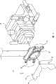
Fig. 1 is the skeleton view of mechanical convergence fixture apparatus of the present invention;
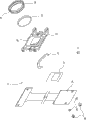
Fig. 2 is the decomposition diagram of the LCD framework among Fig. 1; With
Fig. 3 is the skeleton view of collimator apparatus among Fig. 1.
Now, embodiments of the invention are mechanical convergence fixture apparatus.Fig. 1 is this schematic representation of apparatus, with collectivity mark 10 expressions.This mechanical convergence fixture apparatus 10 has a LCD (" LCD ") frame assembly 12, and this frame assembly 12 is connected with pedestal 14 with a collimation assembly 16, hereinafter will do more detailed introduction to this.
Fig. 2 is the decomposition diagram of LCD frame assembly 12, and framework 22 is connected with little-LCD 24 by a pair of flat head screw 26 that contains pad 28.Among the present invention employed little-used the same in LCD and the prior art equipment.Between little-LCD 24 and framework 22, be provided with a perforate diaphragm (aperturestop) (baffle (mask)) throw light is defined as roughly needed rectangular shape.Pad 32 provides sealing to enter to prevent dust or other dirts between little-LCD 24 and framework 22.The shape of pad 32 depends on the true form of framework 22, so that form complete seal between framework 22 and little-LCD 24.
Fig. 3 is the skeleton view of collimator assembly 16, and vacuum cup 40 can be fixed in LCD frame assembly 12 on the collimator assembly 16 selectively.Be well-known optionally, so in Fig. 3, repeat no more for vacuum cup provides the device of vacuum state.
Under the condition that does not change position of the present invention and scope, can make amendment to it, for example collimator assembly 16 can be one separately customization device and need not assemble by ready-made parts.Again for example, other modes beyond the available previously described vacuum cup 40 temporarily are connected LCD frame assembly 12 on the collimator assembly 16.
The above only is the several examples among the feasible embodiment of the present invention, and under the prerequisite that does not depart from the scope of the present invention with spirit, those skilled in the art can also be easy to make many further modifications and variations.Therefore, above-mentioned disclosed content is not to be limitation of the invention, and simultaneously, the back appending claims can be construed as containing integral body of the present invention.
As previously discussed, the very important point is that little-LCD is accurately located with respect to pedestal 14, otherwise from the focusing of the image of three groups of little-LCD 24 with assemble will be incorrect.The magnification of each passage must strict conformance in addition, and this point is also very important, because otherwise whole pixels are definitely assembled.According to method provided by the invention, the location of LCD frame assembly 12 is with LCD frame assembly 12 and collimator assembly 16 temporary being consolidated by vacuum cup 40, utilize the set screw 52 of collimator assembly 16 subsequently, 58 and 60 position LCD frame assembly 12 and to finish with respect to pedestal 14.Then, the threaded lens abutment ring 38 of rotating band relocates with respect to little-LCD 24 optical element (field lens 33), realizes adjusting to each image magnification ratio with this.
When LCD frame assembly 12 is properly oriented (this is that the operator determines or determines according to other criterions of being set up by estimating), splash into bonding agent 62 (Fig. 1) by the part at least in each register pin 18 and each pilot hole 20, LCD frame assembly 12 for good and all can be connected in pedestal 14.Dripping bonding agent 62 again can be with field lens 33 fix in position on threaded collar 36.Although also can also can reach this purpose with many other bonding agent or bonding way, bonding agent 62 is an epoxide-resin glue among the described herein embodiment.After this, LCD frame assembly 12 just can be broken away from (is to finish by the vacuum state of removing vacuum cup 40 at present embodiment) from collimator assembly 16.Should be noted in the discussion above that according to the described method of the embodiment of the invention, will use three cover apparatus of the present invention so that the image of three kinds of colors can be regulated together.
According to the present invention, can be more accurate usually to the correct location of LCD frame assembly and this location at an easy rate.This be to a great extent because: with those must do both little cheap again and by comparing with the equivalent element that pedestal 14 modes of linking to each other are loaded on the final products, collimator assembly 16 can be done firmly more and accurate.Another reason is to consider that collimator assembly 16 is not fitted together with final products, and can be repeatedly used, thus the marginal cost of collimator apparatus can reduce row almost nil.Become possibility because of the ability that field lens 33 is regulated separately makes simultaneously magnification and each coloured light focusing error to be proofreaied and correct, so just can obtain to assemble and focus on preferable image.A key point herein is to have adopted a kind of aligning gear, this mechanism can handle the recurrent tolerance in the high resolution picture system that causes because of the restriction of creating conditions is relevant, and the described error that causes because of the restriction on creating conditions is as mentioned below to be avoided or reduce to minimum at least.
According to the present invention, provide a kind of aligning gear of correcting the typical tolerances error that is present in high resolving power multichannel image system.It can carry out independent adjustment to magnification and focusing in each passage, to obtain good convergence and focusedimage.A perforate diaphragm 30 is arranged on the assembly, and it is the part of assembly.Little-LCD 24 can aim at perforate diaphragm 30 with high precision.Field lens 33 can be with respect to display device (little-LCD 24) and main casing (pedestal 14) location-independent.This mode required part number is minimum and the dust seal space of a contiguous display device is provided.
The present invention realizes the convergence of sub-pixel precision to entire image.Can finely tune so that adapt with focusing on each channel image magnification with the manufacturing tolerance of lens and display.In assembly, be that seal cavity prevents entering of dust granule with spatial configuration between display and the field lens (nearest optical element).Display also can accurately be aimed at the perforate diaphragm near its installation exactly.Finishing of all these do not need to make or part that installation cost is very high.The method of aiming at focusedimage of being used to of the present invention is very big for the value of compact high precision display, along with improving constantly of this class device precision is then all the more so.Known to the inventor, any prior art effects equivalent of all failing.
Use the method according to this invention, the unique design of LCD frame assembly 12 of the present invention for little-LCD 24 with respect to the location of pedestal 14 with a simple scheme cleverly fixedly is provided.Because mechanical convergence fixture apparatus 10 of the present invention can be made at an easy rate and be applied in the middle of little-LCD optical projection system, and because various advantages described herein, can estimate purposes of the present invention and, no matter be that crucial meaning is all being arranged aspect range of application or the durability in industrial applicability.
Claims (15)
1. method that LCD is fixed in the projection pedestal comprises:
A. temporarily be fixed in LCD on the collimator assembly;
B. LCD is aimed at respect to the projection pedestal;
C. LCD is permanently secured on the projection pedestal;
D. LCD is separated on described collimator assembly;
Described LCD is the little-LCD that is fixed on the LCD frame assembly;
Described LCD frame assembly comprises field lens;
Described LCD frame assembly comprises the governor motion that can adjust the position of described field lens with respect to little-LCD; And
Being adjusted among the step b of field lens position carried out.
2. the method described in claim 1 is characterized in that:
By using bonding agent that LCD is fixed in described framework and completing steps c.
One kind be used for respect to the projection pedestal fixing little-the LCD framework of LCD, comprising:
The rigid frame that has the baffle that is roughly the square type, little-LCD is thereon fixed securely;
This field lens is connected in field lens on the LCD framework with adjustable way, so that can move with respect to little-LCD; With
A plurality of pilot holes are used for described LCD framework is positioned a plurality of register pins that are positioned on the projection pedestal of equivalent amount.
4. LCD framework as claimed in claim 3 is characterized in that, also comprises:
Be used for the bonding agent that pilot hole is fixing with respect to register pin.
5. LCD framework as claimed in claim 3 is characterized in that, also comprises:
Governor motion can be temporarily and LCD framework concrete mutually, so that described LCD framework is located with respect to the projection pedestal.
6. LCD framework as claimed in claim 3 is characterized in that, also comprises:
With described field lens with respect to described little-bonding agent that LCD is fixing.
7. LCD framework as claimed in claim 3 is characterized in that, also comprises:
Be fixed in the perforate diaphragm on the LCD framework.
8. LCD framework as claimed in claim 3 is characterized in that, also comprises:
Pad is used to prevent that dust granule from entering among the LCD framework.
9. one kind with the mechanical convergence fixture apparatus of little-LCD with respect to projector pedestal location, comprising:
Fix the framework of little-LCD; With
Can temporarily described framework be located and fixing collimator assembly with respect to the projector pedestal;
After described framework was fixing with respect to the projector pedestal, described collimator assembly was suitable for removing from described framework;
Also comprise field lens, itself and described framework are movably fixed, so that the relative position between field lens and the little-LCD is adjustable.
10. mechanical convergence fixture apparatus as claimed in claim 9 is characterized in that,
Also comprise a kind of sticky object, described collimating components was being bonded to described framework on the described projector pedestal before removing on the described framework.
11. mechanical convergence fixture apparatus as claimed in claim 10 is characterized in that, described sticky object is a kind of bonding agent.
12. mechanical convergence fixture apparatus as claimed in claim 10 is characterized in that, described sticky object is a kind of epoxy resin.
13. mechanical convergence fixture apparatus as claimed in claim 9 is characterized in that,
Described field lens is connected with framework by threaded collar, so that can field lens be moved with respect to little-LCD by rotation field lens housing.
14. mechanical convergence fixture apparatus as claimed in claim 9 is characterized in that, also comprises:
Be fixed in perforate diaphragm on the described framework with respect to little-LCD.
15. mechanical convergence fixture apparatus as claimed in claim 9 is characterized in that, also comprises:
Gasket seal between little-LCD and described framework.
Applications Claiming Priority (2)
| Application Number | Priority Date | Filing Date | Title |
|---|---|---|---|
| US09/047,292 | 1998-03-24 | ||
| US09/047,292 US6106120A (en) | 1998-03-24 | 1998-03-24 | Mechanical convergence fixture apparatus and method |
Publications (2)
| Publication Number | Publication Date |
|---|---|
| CN1301359A CN1301359A (en) | 2001-06-27 |
| CN100458554C true CN100458554C (en) | 2009-02-04 |
Family
ID=21948146
Family Applications (1)
| Application Number | Title | Priority Date | Filing Date |
|---|---|---|---|
| CNB998063312A Expired - Fee Related CN100458554C (en) | 1998-03-24 | 1999-03-22 | Mechanical convergence fixture apparatus and method |
Country Status (6)
| Country | Link |
|---|---|
| US (2) | US6106120A (en) |
| EP (1) | EP1066547A4 (en) |
| JP (1) | JP2002507785A (en) |
| CN (1) | CN100458554C (en) |
| CA (1) | CA2324957C (en) |
| WO (1) | WO1999049363A1 (en) |
Families Citing this family (13)
| Publication number | Priority date | Publication date | Assignee | Title |
|---|---|---|---|---|
| JP3271600B2 (en) * | 1999-02-16 | 2002-04-02 | 日本電気株式会社 | Liquid crystal display device and its heat control method |
| JP4284766B2 (en) * | 1999-07-29 | 2009-06-24 | ソニー株式会社 | Projector device |
| US6377318B1 (en) * | 2000-01-18 | 2002-04-23 | Aurora Systems, Inc. | Multi-channel imaging engine apparatus |
| JP4697999B2 (en) * | 2000-05-31 | 2011-06-08 | 三菱電機株式会社 | Projection-type image display device |
| JP3744402B2 (en) * | 2001-10-16 | 2006-02-08 | セイコーエプソン株式会社 | Manufacturing method of optical device and reference position generating device |
| TWI222832B (en) * | 2003-04-29 | 2004-10-21 | Coretronic Corp | Assembling method and apparatus for light engine |
| JP4569113B2 (en) * | 2004-01-22 | 2010-10-27 | 富士フイルム株式会社 | projector |
| US7673995B2 (en) * | 2004-07-06 | 2010-03-09 | Northrop Grumman Corporation | System and method for projector alignment |
| JP2006078637A (en) * | 2004-09-08 | 2006-03-23 | Seiko Epson Corp | Liquid crystal device and projection display device |
| JP2010185947A (en) * | 2009-02-10 | 2010-08-26 | Shimadzu Corp | Display device |
| JP5140756B2 (en) * | 2009-02-19 | 2013-02-13 | パナソニック株式会社 | Camera device and method of assembling camera device |
| CN108152990B (en) * | 2017-12-25 | 2020-05-05 | 中国航空工业集团公司洛阳电光设备研究所 | Multi-degree-of-freedom lens clamping and adjusting device for centering instrument |
| CN113790671B (en) * | 2021-09-03 | 2022-05-17 | 苏州天准科技股份有限公司 | Bore adjustable epi-illumination source and image measuring instrument |
Citations (3)
| Publication number | Priority date | Publication date | Assignee | Title |
|---|---|---|---|---|
| US5329391A (en) * | 1992-05-20 | 1994-07-12 | Canon Kabushiki Kaisha | Process for fixing liquid crystal panel to fixing plate using height regulating pins which are removed after curing adhesive |
| US5418586A (en) * | 1991-02-22 | 1995-05-23 | Seiko Epson Corporation | Projection type liquid crystal projector |
| US5648860A (en) * | 1992-10-09 | 1997-07-15 | Ag Technology Co., Ltd. | Projection type color liquid crystal optical apparatus |
Family Cites Families (10)
| Publication number | Priority date | Publication date | Assignee | Title |
|---|---|---|---|---|
| JPH0614255B2 (en) * | 1989-07-20 | 1994-02-23 | 三洋電機株式会社 | LCD projector |
| EP0409246B1 (en) * | 1989-07-20 | 1997-04-23 | SANYO ELECTRIC Co., Ltd. | Liquid crystal projector |
| NL9000115A (en) * | 1990-01-18 | 1991-08-16 | Philips Nv | DEVICE FOR PROJECTING TELEVISION IMAGES. |
| JP2843720B2 (en) * | 1992-09-25 | 1999-01-06 | 株式会社ケンウッド | LCD module position adjustment mechanism for LCD projector |
| US5624174A (en) * | 1993-08-25 | 1997-04-29 | Kopin Corporation | Display panel mount for projection display system |
| US5455678A (en) * | 1993-08-25 | 1995-10-03 | Kopin Corporation | Method for mounting light valves for projection display system |
| EP0677766B1 (en) * | 1993-09-30 | 2001-12-12 | Citizen Watch Co. Ltd. | Liquid crystal projector |
| JPH08166572A (en) * | 1994-12-13 | 1996-06-25 | Mitsubishi Electric Corp | Projection type display device |
| US5721602A (en) * | 1995-10-11 | 1998-02-24 | International Business Machines Corporation | Mechanical packaging and thermal management of flat mirror arrays |
| JP3767047B2 (en) * | 1996-04-26 | 2006-04-19 | セイコーエプソン株式会社 | Projection display |
-
1998
- 1998-03-24 US US09/047,292 patent/US6106120A/en not_active Expired - Lifetime
-
1999
- 1999-03-22 JP JP2000538273A patent/JP2002507785A/en active Pending
- 1999-03-22 CA CA002324957A patent/CA2324957C/en not_active Expired - Fee Related
- 1999-03-22 CN CNB998063312A patent/CN100458554C/en not_active Expired - Fee Related
- 1999-03-22 EP EP99914038A patent/EP1066547A4/en not_active Withdrawn
- 1999-03-22 WO PCT/US1999/006255 patent/WO1999049363A1/en active Application Filing
-
2000
- 2000-08-21 US US09/643,131 patent/US6416187B1/en not_active Expired - Lifetime
Patent Citations (3)
| Publication number | Priority date | Publication date | Assignee | Title |
|---|---|---|---|---|
| US5418586A (en) * | 1991-02-22 | 1995-05-23 | Seiko Epson Corporation | Projection type liquid crystal projector |
| US5329391A (en) * | 1992-05-20 | 1994-07-12 | Canon Kabushiki Kaisha | Process for fixing liquid crystal panel to fixing plate using height regulating pins which are removed after curing adhesive |
| US5648860A (en) * | 1992-10-09 | 1997-07-15 | Ag Technology Co., Ltd. | Projection type color liquid crystal optical apparatus |
Also Published As
| Publication number | Publication date |
|---|---|
| US6106120A (en) | 2000-08-22 |
| US6416187B1 (en) | 2002-07-09 |
| CA2324957A1 (en) | 1999-09-30 |
| EP1066547A4 (en) | 2004-05-06 |
| WO1999049363A1 (en) | 1999-09-30 |
| EP1066547A1 (en) | 2001-01-10 |
| JP2002507785A (en) | 2002-03-12 |
| CN1301359A (en) | 2001-06-27 |
| CA2324957C (en) | 2008-06-03 |
Similar Documents
| Publication | Publication Date | Title |
|---|---|---|
| CN100458554C (en) | Mechanical convergence fixture apparatus and method | |
| US9140973B2 (en) | Rear projection imaging system with image warping distortion correction system and associated method | |
| US6909556B2 (en) | Design of prism assemblies and kernel configurations for use in projection systems | |
| US20050195504A1 (en) | Adjustable convergence device for a projector and projector equipped with such a convergence device | |
| WO2014023990A1 (en) | Laser projector | |
| JPH07162878A (en) | Convergence adjusting circuit and projection type display device | |
| JP3031329B2 (en) | Convergence mechanism and projector using the same | |
| US2948891A (en) | Television receivers | |
| US6271894B1 (en) | Arrangement for setting an image display device with a housing | |
| US7216990B2 (en) | Integrated lamp and aperture alignment method and system | |
| US6421100B1 (en) | Method and apparatus for checking the alignment of a projection television lens | |
| RU2164653C1 (en) | Target simulator for ammunition with television homing head | |
| US20030085848A1 (en) | Method for initialization and stabilization of distortion correction in a head up display unit | |
| CN219978687U (en) | Projection equipment | |
| US3009015A (en) | Color-image-reproducing apparatus of the image-projection type | |
| JPH05150211A (en) | Projection type liquid crystal display device | |
| Lloyd et al. | Towards the rapid and complete automated alignment of multi-projector display systems | |
| EP1210820A2 (en) | Method and apparatus for an improved wide-angle display system | |
| JP2001100185A (en) | Structure and method for mounting liquid crystal display element in liquid crystal projector | |
| JPH02168532A (en) | Crt assembly device | |
| KR20030083496A (en) | Image unit bonding unit for convergence control in Projection Television | |
| JPH08166572A (en) | Projection type display device | |
| JPH11122640A (en) | Adjustment method for projector and adjustment device | |
| Whyte et al. | Wide-Angle, Multiviewer, Infinity Display System | |
| JP2002350813A (en) | Projection type liquid crystal display device |
Legal Events
| Date | Code | Title | Description |
|---|---|---|---|
| C06 | Publication | ||
| PB01 | Publication | ||
| C10 | Entry into substantive examination | ||
| SE01 | Entry into force of request for substantive examination | ||
| C14 | Grant of patent or utility model | ||
| GR01 | Patent grant | ||
| C17 | Cessation of patent right | ||
| CF01 | Termination of patent right due to non-payment of annual fee |
Granted publication date: 20090204 Termination date: 20100322 |