CN100458547C - Imaging device having a capability of checking connection with a flash unit, and system thereof - Google Patents
Imaging device having a capability of checking connection with a flash unit, and system thereof Download PDFInfo
- Publication number
- CN100458547C CN100458547C CNB200410100273XA CN200410100273A CN100458547C CN 100458547 C CN100458547 C CN 100458547C CN B200410100273X A CNB200410100273X A CN B200410100273XA CN 200410100273 A CN200410100273 A CN 200410100273A CN 100458547 C CN100458547 C CN 100458547C
- Authority
- CN
- China
- Prior art keywords
- imaging device
- unit
- flashing light
- light unit
- flash
- Prior art date
- Legal status (The legal status is an assumption and is not a legal conclusion. Google has not performed a legal analysis and makes no representation as to the accuracy of the status listed.)
- Expired - Fee Related
Links
Images


Classifications
-
- G—PHYSICS
- G03—PHOTOGRAPHY; CINEMATOGRAPHY; ANALOGOUS TECHNIQUES USING WAVES OTHER THAN OPTICAL WAVES; ELECTROGRAPHY; HOLOGRAPHY
- G03B—APPARATUS OR ARRANGEMENTS FOR TAKING PHOTOGRAPHS OR FOR PROJECTING OR VIEWING THEM; APPARATUS OR ARRANGEMENTS EMPLOYING ANALOGOUS TECHNIQUES USING WAVES OTHER THAN OPTICAL WAVES; ACCESSORIES THEREFOR
- G03B15/00—Special procedures for taking photographs; Apparatus therefor
- G03B15/02—Illuminating scene
- G03B15/03—Combinations of cameras with lighting apparatus; Flash units
- G03B15/05—Combinations of cameras with electronic flash apparatus; Electronic flash units
-
- H—ELECTRICITY
- H04—ELECTRIC COMMUNICATION TECHNIQUE
- H04N—PICTORIAL COMMUNICATION, e.g. TELEVISION
- H04N23/00—Cameras or camera modules comprising electronic image sensors; Control thereof
- H04N23/56—Cameras or camera modules comprising electronic image sensors; Control thereof provided with illuminating means
-
- H—ELECTRICITY
- H04—ELECTRIC COMMUNICATION TECHNIQUE
- H04N—PICTORIAL COMMUNICATION, e.g. TELEVISION
- H04N23/00—Cameras or camera modules comprising electronic image sensors; Control thereof
- H04N23/60—Control of cameras or camera modules
-
- G—PHYSICS
- G03—PHOTOGRAPHY; CINEMATOGRAPHY; ANALOGOUS TECHNIQUES USING WAVES OTHER THAN OPTICAL WAVES; ELECTROGRAPHY; HOLOGRAPHY
- G03B—APPARATUS OR ARRANGEMENTS FOR TAKING PHOTOGRAPHS OR FOR PROJECTING OR VIEWING THEM; APPARATUS OR ARRANGEMENTS EMPLOYING ANALOGOUS TECHNIQUES USING WAVES OTHER THAN OPTICAL WAVES; ACCESSORIES THEREFOR
- G03B2215/00—Special procedures for taking photographs; Apparatus therefor
- G03B2215/05—Combinations of cameras with electronic flash units
Abstract
In a system including an imaging device and a flash unit, the imaging device includes an imaging device flash start command terminal adapted to output a flash start command signal to the flash unit, and an output unit adapted to output a terminal connection check signal to the flash unit via the imaging device flash start command terminal, and the flash unit includes a flash unit flash start command terminal adapted to receive the flash start command signal from the imaging device, a detection unit adapted to detect the terminal connection check signal received from the imaging device via the flash unit flash start command terminal, and a connection state evaluation unit adapted to evaluate a terminal connection state such that the connection state evaluation unit determines that the imaging device and the flash unit are connected to each other via the imaging device flash start command terminal and the flash unit flash start command terminal in a required connection state if the detection unit detects the terminal connection check signal.
Description
Technical field
The present invention relates to be used for by flash of light starting command end, the technology whether the check flashing light unit links to each other with imaging device such as camera with kilter by this flash of light starting command end, transmits the starting command that glistens between imaging device and flashing light unit.
Background technology
It is a kind of by carry out test communications between imaging device and flashing light unit that 2000-89328 number Japanese publication discloses, and whether the link flashing light unit of upchecking is connected to the technology of imaging device with kilter.
In this conventional art, by via communicating with the communication ends discrete setting of flash command end, that be used to send flash of light starting command signal, being connected between check imaging device and the flashing light unit.Because be that basis is judged the test of the connection of communication ends, so if the connection of flash of light starting command (FSC) end is bad, but the connection of communication ends is good, and then this error of performance ground determines that the connection of FSC end is good.If make this wrong judgement, then when photographic images, flashing light unit is not worked, and occurs under-exposure.
Summary of the invention
In view of the above problems, the invention provides the imaging device that is connected, the flashing light unit of the FSC end between a kind of have the ability correct check imaging device and the flashing light unit and comprise flashing light unit and the system of imaging device.
According to an aspect, the invention provides a kind of imaging device, this imaging device comprises: flash of light starting command end is suitable for flash of light starting command signal is outputed to flashing light unit; And output unit, be suitable for will holding connection check signal to deliver to flashing light unit by flash of light starting command end, whether be connected to each other together with the connection status that requires to determine imaging device and flashing light unit by flash of light starting command end.Receiving that when pointing out that flashing light unit have the ability to utilize end to connect the check signal to carry out the signal of connection status check, output unit will hold to connect and check signal to output to flashing light unit.
According to another aspect, the invention provides a kind of flashing light unit, this flashing light unit comprises: flash of light starting command end is suitable for receiving flash of light starting command signal from imaging device; Detecting unit is suitable for detecting the end that receives from imaging device by flash of light starting command end and connects the check signal; And connection status assessment unit, be suitable for assessment end connection status, connect the check signal if make detecting unit detect end, then the connection status assessment unit determines that imaging device and flashing light unit are connected to each other together with the connection status that requires by flash of light starting command end.
According to another aspect, the invention provides a kind of system that comprises imaging device and flashing light unit.This imaging device comprises: imaging device flash of light starting command end is arranged on the imaging device, and is suitable for flash of light starting command signal is outputed to flashing light unit; And output unit, be suitable for will holding connection check signal to deliver to flashing light unit by imaging device flash of light starting command end.Flashing light unit comprises: flashing light unit flash of light starting command end is arranged on the flashing light unit, and is suitable for receiving flash of light starting command signal from imaging device; Detecting unit is suitable for detecting the end that receives from imaging device by flashing light unit flash of light starting command end and connects the check signal; And connection status assessment unit, be suitable for assessment end connection status, connect the check signal if make detecting unit detect end, then the connection status assessment unit determines that imaging device and flashing light unit are connected to each other with the connection status that requires and are in the same place by imaging device flash of light starting command end and the flashing light unit starting command end that glistens.
According to another aspect, the invention provides a kind of imaging device, this imaging device comprises: flash of light starting command end is suitable for flash of light starting command signal is outputed to flashing light unit; Detecting unit is suitable for detecting the end that receives from flashing light unit by flash of light starting command end and connects the check signal; And connection status assessment unit, be suitable for assessment end connection status, connect the check signal if make detecting unit detect end, then the connection status assessment unit determines that imaging device and flashing light unit are connected to each other together with the connection status that requires by flash of light starting command end.
According to another aspect, the invention provides a kind of flashing light unit, this flashing light unit comprises: flash of light starting command end is suitable for receiving flash of light starting command signal from imaging device; And output unit, be suitable for will holding connection check signal to deliver to imaging device by flash of light starting command end, whether be connected to each other together with the connection status that requires to determine imaging device and flashing light unit by flash of light starting command end.
According to another aspect, the invention provides a kind of system that comprises imaging device and flashing light unit.This imaging device comprises: imaging device flash of light starting command end is arranged on the imaging device, and is suitable for flash of light starting command signal is outputed to flashing light unit; Detecting unit is suitable for detecting the end that receives from flashing light unit by imaging device flash of light starting command end and connects the check signal; And connection status assessment unit, be suitable for assessment end connection status, connect the check signal if make detecting unit detect end, then the connection status assessment unit determines that imaging device and flashing light unit are connected to each other together with the connection status that requires by imaging device flash of light starting command end.Flashing light unit comprises: flashing light unit flash of light starting command end is arranged on the flashing light unit, and is suitable for receiving flash of light starting command signal from imaging device; And output unit, be suitable for connecting the check signal by flashing light unit flash of light starting command end output terminal.
According to the detailed description of with reference to the accompanying drawings exemplary embodiments being done, it is more obvious that other features and advantages of the present invention will become.
Description of drawings
Fig. 1 is the block scheme that illustrates according to the circuit arrangement of the imaging device of first embodiment of the invention and flashing light unit;
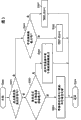
Fig. 2 is the process flow diagram that illustrates according to the performed processing procedure of the connection of first embodiment of the invention imaging device check FSC end;
Fig. 3 is the process flow diagram that illustrates according to the performed processing procedure of the connection of first embodiment of the invention flashing light unit check FSC end;
Fig. 4 is the process flow diagram that the common treatment process of carrying out according to the first embodiment of the invention flashing light unit is shown;
Fig. 5 is the block scheme that illustrates according to the circuit arrangement of the imaging device of second embodiment of the invention and flashing light unit;
Fig. 6 is the process flow diagram that illustrates according to the performed processing procedure of the connection of second embodiment of the invention imaging device check FSC end;
Fig. 7 is the block scheme that illustrates according to the circuit arrangement of the imaging device of third embodiment of the invention and flashing light unit;
Fig. 8 is the process flow diagram that illustrates according to the performed processing procedure of the connection of third embodiment of the invention imaging device check FSC end.
Embodiment
Below in conjunction with accompanying drawing, further describe the present invention with reference to each embodiment.
First embodiment
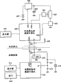
Fig. 1 is the block scheme such as the circuit arrangement of the imaging device of camera or digital camera and flashing light unit that illustrates according to first embodiment of the invention.The structure of imaging device at first, is described with reference to figure 1.In Fig. 1, the operation of the microcomputer 110 of imaging device (below be called ID microcomputer 110) control imaging device, and required various judgements in the executable operations process.Imaging device has the display 111 that is used to show various information.By its X_ON end, will glisten starting command (FSC) signal when ID microcomputer 100 outputs to switching device 112, switching device 112 outputs to flashing light unit with fsc signal.Imaging device is connected to each other by the coupling part with flashing light unit is in the same place.Coupling part 120 comprises: the CLK end is used for the data communication clock signal is sent to flashing light unit from imaging device; The DCS end is used for synchronous by the clock signal of CLK end transmission data being sent to flashing light unit from imaging device; The DSC end is used for synchronous by the clock signal of CLK end transmission data being sent to imaging device from flashing light unit; GND end is used for being connected GND (ground wire) between imaging device and flashing light unit; And FSC end (in Fig. 1, only utilizing X to represent), be used for fsc signal is delivered to flashing light unit.The FSC end links to each other with the negative electrode of switching device 112 with diode 114.By resistor 113, switching device 115 and diode 114, the FSC end that FSC end is applied specific voltage connects check signal (below be called FSCT connect the check signal).Switching device 115 is connected to the ON end of ID microcomputer 110, and ID microcomputer 110 makes its on/off.Shutter unit 116 is arranged on the front of the imageing sensor of imaging device.By first heavy curtain (curtain) and second heavy curtain are moved, the light of imageing sensor is incided in shutter unit 116 controls.If ID microcomputer 110 detects the first mobile heavy curtain and arrives ad-hoc location, then ID microcomputer 110 is set to high level with the X-ON end.
The structure of flashing light unit is described now.The operation of the microcomputer 100 of flashing light unit (below be called FU microcomputer 100) control flashing light unit, and required various judgements in the executable operations process.Battery 101 is as power supply.The low pressure of utilizing battery 101 to provide, booster circuit 102 produces high voltage to several hectovolts.The high voltage style storage of electrical energy that main capacitor 103 provides with booster circuit 102.The transformation of electrical energy that discharge tube 105 will be stored in the main capacitor 103 is a light.Flip-flop circuit 104 provides the high trigger voltage of several hectovolts, so that discharge tube 105 begins discharge.Charge/discharge control circuit 106 comprises the switching device such as IGBT (igbt), and the discharge of control discharge tube 105.This flashing light unit also has display 107.
Be connected to by its flashing light unit imaging device coupling part 120 each the end in, the FSC end not only is connected to the X end of FU microcomputer 100, and, be connected to be arranged on FU microcomputer 100 in the AD end that links to each other of A-D converter (not shown), make to connect from FSCT imaging device output and that be input to the FSC end and check voltage of signals monitored by A-D converter.With fsc signal when the switching device 112 of imaging device is applied to the FSC end of FU microcomputer 100, FU microcomputer 100 control triggering electric circuits 104 are to apply the high trigger voltage of several hectovolts to discharge tube 105.
When the release-push (not shown) to imaging device applied first stroke (stroke) (pressing the position that partways), whether ID microcomputer 110 executive routines were in normal connection status with check FSC end.Below, will be used to check the FSC end whether to be in the routine of normal connection status with reference to flowchart text shown in Figure 2.
At step S105, the routine of the connection of the FSC end of ID microcomputer 110 end check imaging devices.
Although in this example, first stroke of response release-push, the routine of the connection of ID microcomputer 110 starting check FSC ends, the time of starting this routine is not limited thereto.Can select this time in every way.For example, can respond second stroke (pressing the second place) of release-push, perhaps connect the power switch of imaging device, start this routine.Also can detect when flashing light unit has been installed, perhaps when activating imaging device or flashing light unit, start this routine at the installation and measuring switch.Can be provided for detecting the device of connection, and can respond the operation of this device, start this routine.
Below, the process that is connected that will hold with reference to the communication process and the check FSC of 100 execution of the FU microcomputer in the flowchart text flashing light unit shown in Figure 3.
If by the CLK end, FU microcomputer 100 is from the clock signal of ID microcomputer 110 receptions one byte, and then FU microcomputer 100 begins to start the communication disruption routine from step S200.At step S201, FU microcomputer 100 determines whether the data that ID microcomputer 110 sends are device attribute data of the ability of expression imaging device.If not, then processing procedure enters step S202.At step S202, FU microcomputer 100 determines whether the reception data are check orders (at step S102 shown in Figure 2) that ID microcomputer 110 sends, with the connection whether capable check FSC holds of check flashing light unit.If this ability is arranged, then processing procedure enters step S208, otherwise processing procedure enters step S203.
Because receiving data is not to be used to check whether the have the ability check order of connection of check FSC end of flashing light unit, so processing procedure enters under the situation of step S203, FU microcomputer 100 communicates process according to receiving data/order therein.After finishing communication process, processing procedure enters step S204, and at step S204, processing procedure is returned from the communication disruption routine.Determine to receive data therein and be and be used to check whether the have the ability check order of connection of check FSC end of flashing light unit, and therefore processing procedure enters under the situation of step S208, FU microcomputer 100 returns data to ID microcomputer 110, has the ability to check the connection of FSC end with notice FU microcomputer 100.Behind the completing steps S208, processing procedure enters step S204, and at step S204, processing procedure is returned from the communication disruption routine.
Therein at step S201, under the device attribute data conditions of the ability that FU microcomputer 100 definite data that receive from ID microcomputer 110 are expression imaging devices, FU microcomputer 100 makes processing procedure enter step S205, whether has the ability to check the connection of FSC end to determine imaging device.If there is not this ability, then processing procedure enters step S206, at step S206, and FU microcomputer 100 set TEST_FLG=0 (not having the connection of ability test FSC end) to point out imaging device.If determine the connection that the capable check of imaging device FSC holds at step S205, then processing procedure enters step S207, at step S207, and FU microcomputer 100 set TEST_FLG=1 (with the connection of pointing out that the capable check of imaging device FSC holds).In both cases, then, processing procedure enters step S204, to return from the communication disruption routine.
Below with reference to the common treatment process of Fig. 4 explanation in the execution of the control glitter down unit of FU microcomputer 100.
When the power supply of connecting flashing light unit closed (not shown), FU microcomputer 100 began operation from step S210.At step S211, FU microcomputer 100 CGH end is set to high level, to activate booster circuit 102.At step S212, FU microcomputer 100 determines whether TEST_FLG is 1.If TEST_FLG=1 (that is, the connection of check FSC end if imaging device is had the ability), then processing procedure enters step S216.TEST_FLG=0, then processing procedure enters step S213, and at step S213, imaging device is carried out desired other operation.At step S214, FU microcomputer 100 determines whether the power switch (not shown) is disconnected.If be disconnected, then processing procedure enters step S215, and at step S215, processing procedure is returned from this routine, otherwise processing procedure is returned step S212.
In first embodiment, as mentioned above, imaging device comprises: the FSC end that is used for fsc signal is delivered to flashing light unit; And the device that the FSCT that is used to produce predetermined voltage connects the check signal (comprises diode 114, the each several part of switching device 115, resistor 113 and the ID microcomputer 110 relevant) with the processing procedure of step S104 shown in Figure 2, and flashing light unit comprises: the FSC end is used for receiving fsc signal from imaging device; Pick-up unit (each several part that comprises the A-D converter (not shown) that is arranged in the flashing light unit and the FU microcomputer 100 relevant with the processing procedure of step S216 shown in Figure 4 and S217) is used to detect the FSCT that imaging device applies the FSC end and connects the check signal; And the device (each several part that comprises the FU microcomputer 100 relevant) that is used for determining connection status with the processing procedure of step S217-S214 shown in Figure 4 or step S217-S218, make that detecting FSCT at pick-up unit connects the check voltage of signals just often, determine that being connected of FSC end between imaging device and the flashing light unit is in normal condition, and when definite this voltage is undesired, determine that this connection is in malfunction, therefore being connected of FSC end between imaging device and the flashing light unit can be checked, and luminous test needn't be carried out.Therefore, not only can check the communication ends of coupling part 120 whether to be in normal connection status, and can determine whether the FSC end is in normal connection status.
Being connected when being in malfunction of FSC end between imaging device and flashing light unit, display alarm on the display 107 of flashing light unit (the step S218 of the routine (shown in Figure 4) that FU microcomputer 100 is carried out) is notified the user so that this connection is in malfunction.
Second embodiment
Fig. 5 is the block scheme that illustrates according to the circuit arrangement of the imaging device of second embodiment of the invention and flashing light unit.The circuit arrangement of imaging device at first, is described with reference to figure 5.In Fig. 5, the operation of the microcomputer 310 of imaging device (below be called ID microcomputer 310) control imaging device, and required various judgements in the executable operations process.Imaging device has the display 311 that is used to show various information.When ID microcomputer 310 its X_ON ends are set to high level, connect switching device 312.Therefore, fsc signal outputs to flashing light unit.Imaging device is connected to each other by coupling part 320 with flashing light unit is in the same place.Coupling part 320 comprises: the CLK end is used to make the data communication clock signal to be sent to flashing light unit from imaging device; The DCS end is used for making data be sent to flashing light unit from imaging device with synchronous by the clock signal of CLK end transmission; The DSC end is used for making data be sent to imaging device from flashing light unit with synchronous by the clock signal of CLK end transmission; The GND end is used to connect the GND between imaging device and the flashing light unit; And the FSC end, be used for fsc signal is sent to flashing light unit.By switching device 314, the FSC end is connected to the AD end of ID microcomputer 310.The AD end is connected to the A-D converter (not shown among Fig. 5) that is arranged in the ID microcomputer 310.Switching device 314 is connected to the AD_ON end of ID microcomputer 310, and ID microcomputer 310 makes its on/off.Resistor 313 is connected to the AD end of ID microcomputer 310.Shutter unit 316 is arranged on the front of the imageing sensor in the imaging device.By first heavy curtain and second heavy curtain are moved, the light of imageing sensor is incided in shutter unit 316 controls.If ID microcomputer 310 detects the first mobile heavy curtain and arrived ad-hoc location, then ID microcomputer 310 is set to high level with the X-ON end.
The structure of flashing light unit is described now.The operation of the microcomputer 300 of flashing light unit (below be called FU microcomputer 300) control flashing light unit, and required various judgements in the executable operations process.Battery 301 is as power supply.The low pressure of utilizing battery 301 to provide, booster circuit 302 produces high voltage to several hectovolts.The high voltage style storage of electrical energy that main capacitor 303 provides with booster circuit 302.The transformation of electrical energy that discharge tube 305 will be stored in the main capacitor 303 is a light.Flip-flop circuit 304 provides the high trigger voltage of several hectovolts, so that discharge tube 305 begins discharge.Charge/discharge control circuit 306 comprises the switching device such as IGBT, and the discharge of control discharge tube 305.This flashing light unit also has display 307.
The X end of FU microcomputer 300 not only is connected to flashing light unit and is connected to part imaging device, coupling part 320 by it, and be connected to the power lead that its voltage is lower than the fsc signal of switching device 312 output by resistor 308, make the voltage of delivering to the X end of FU microcomputer 300 by resistor 308 connect the check signal as the FSCT that is sent to imaging device from flashing light unit.Except foregoing, in function and configuration aspects, therefore this flashing light unit does not do repeat specification at this with identical according to the flashing light unit of first embodiment (Fig. 1).
When the release-push (not shown) to imaging device applied first stroke, whether ID microcomputer 310 executive routines were in normal connection status with check FSC end.Be used to check the FSC end whether to be in the routine of normal connection status below with reference to flowchart text shown in Figure 6.
On the contrary, if determine the connection that the capable check of flashing light unit FSC holds at step S302, then processing procedure enters step S305, and at step S305, it is high level that ID microcomputer 310 is held set with AD_ON, to connect switching device 314.At step S306, by being digital form, measuring FSCT that flashing light unit produces and the FSC end by the coupling part 320 between imaging device and the flashing light unit is applied to the AD end by switching device 314 then and is connected and checks voltage of signals voltage transformation.
At step S307, according to the result of analog to digital conversion, ID microcomputer 310 determines that the FSCT that receive connect that the check voltage of signals equal or greater than threshold value.If this voltage is equal to, or greater than threshold value, then determines imaging device and being connected of FSC end be in normal condition between the flashing light unit.In this case, processing procedure enters step S308.Yet, determining that at step S307 voltage is lower than under the situation of threshold value, determine that being connected of FSC end between imaging device and the flashing light unit is in malfunction, then, processing procedure enters step S309.At step S309, ID microcomputer 310 is presented on the display 311 alarm, notifies the user being in malfunction in being connected of the end of the FSC between imaging device and the flashing light unit.For example, the indication by forbidding finishing the capacitor that is full of flashing light unit or by making this indication flicker provides this notice.At step S308, ID microcomputer 310 AD_ON end is set to low level, with cut-off switch device 314.Then, processing procedure enters step S310, and at step S310, ID microcomputer 310 finishes that imaging devices carry out is used to check the routine of the connection of FSC end.
Although in this example, first stroke of response release-push, the routine of the connection of ID microcomputer 310 starting check FSC ends, the time of starting this routine is not limited thereto.Can select this time in every way.For example, can respond second stroke (pressing the second place) of release-push, perhaps connect the power switch of imaging device, start this routine.Also can detect when flashing light unit has been installed, perhaps when activating imaging device or flashing light unit, start this routine at the installation and measuring switch.Can be provided for detecting the device of connection, and can respond the operation of this device, start this routine.
In a second embodiment, as mentioned above, flashing light unit comprises: the FSC end is used for receiving fsc signal from imaging device; Be used for the FSC end is applied the device (resistor 308) of the FSCT connection check signal of predetermined voltage, and imaging equipment comprises: the FSC end that is used for fsc signal is sent to flashing light unit; Pick-up unit (each several part that comprises switching device 314, resistor 313 and the ID microcomputer 310 relevant with the processing procedure of step S305 shown in Figure 6 and S306) is used to detect the FSCT that flashing light unit applies the FSC end and connects the check signal; And the device (each several part that comprises the ID microcomputer relevant) that is used for determining connection status with the processing procedure of step S307-S308 shown in Figure 6 or step S307-S309, make that detecting FSCT at pick-up unit connects the check voltage of signals just often, determine that being connected of FSC end between imaging device and the flashing light unit is in normal condition, and when definite this voltage is undesired, determine that this connection is in malfunction, therefore being connected of FSC end between imaging device and the flashing light unit can be checked, and luminous test needn't be carried out.
Being connected when being in malfunction of FSC end between imaging device and flashing light unit, display alarm on display 311 (the step S309 of the routine (shown in Figure 6) that ID microcomputer 310 is carried out) is notified the user so that this connection is in malfunction.
In a second embodiment, because connect switching device 314 during the connection of the capable check of the flashing light unit only on being installed in imaging device FSC end, even so the flashing light unit on being installed in imaging device is when the FSC between imaging device and flashing light unit end is applied high-tension type, still the AD end of ID microcomputer is not applied high pressure.Can protect ID microcomputer 310 like this.The such flashing light unit that to export high pressure below is called the high pressure flashing light unit.
The 3rd embodiment
Fig. 7 is the block scheme that illustrates according to the circuit arrangement of the imaging device of third embodiment of the invention and flashing light unit.The structure of imaging device at first, is described with reference to figure 7.In Fig. 7, ID microcomputer 410, display 411 and switching device 412 are with identical according to the appropriate section of above-mentioned first embodiment and second embodiment.By coupling part 420, imaging device and flashing light unit are connected to each other together.Coupling part 420 comprises: the GND end is used to connect the GND between imaging device and the flashing light unit; And the FSC end, be used for fsc signal is sent to flashing light unit from imaging device.The resistor 413 of series connection and resistor 414 are connected between FSC end and the GND, and the node between resistor 413 and 414 is connected to the AD end of ID microcomputer 410.Zener diode 415 is connected between FSC end and the GND.Shutter unit 416 is arranged on the front of the imageing sensor of imaging device.By first heavy curtain and second heavy curtain are moved, the light of imageing sensor is incided in shutter unit 416 controls.If ID microcomputer 410 detects the first mobile heavy curtain and arrived ad-hoc location, then ID microcomputer 410 is set to high level with the X-ON end.
Flashing light unit on being installed in imaging device be the high pressure type the time, imaging device and flashing light unit are applied high pressure (a few hectovolt) by FSC end that it is connected to each other coupling part 420 together.Even the FSC end is being applied under the situation of high pressure, Zener diode 415 is set guarantees to hold the voltage that applies not to be higher than predetermined value the AD of ID microcomputer 410.That is, even when ID microcomputer 410 is the type of not handle high voltages, Zener diode 415 prevents that the AD end from bearing the high pressure that may destroy ID microcomputer 410.
The structure of flashing light unit is described now.The operation of the microcomputer 400 of flashing light unit (below be called FU microcomputer 400) control flashing light unit, and required various judgements in the executable operations process.Battery 401 is as power supply.The low pressure of utilizing battery 401 to provide, booster circuit 402 produces high voltage to several hectovolts.The high voltage style storage of electrical energy that main capacitor 403 provides with booster circuit 402.The transformation of electrical energy that discharge tube 405 will be stored in the main capacitor 403 is a light.Flip-flop circuit 404 provides the high trigger voltage of several hectovolts, so that discharge tube 405 begins discharge.Charge/discharge control circuit 406 comprises the switching device such as IGBT, and the discharge process of control discharge tube 405.This flashing light unit also has display 407.
The X end of FU microcomputer 400 not only is connected to flashing light unit and is connected to FSC end imaging device, the coupling part by it, and be connected to the power lead that its voltage is lower than the fsc signal of switching device 412 output by resistor 408, make the voltage of delivering to the X end of FU microcomputer 400 by resistor 408 connect the check signal as the FSCT that is sent to imaging device from flashing light unit.Except foregoing, in function and configuration aspects, therefore this flashing light unit does not do repeat specification at this with identical according to the flashing light unit of second embodiment (Fig. 5).
When the release-push (not shown) to imaging device applied first stroke (pressing the position that partways), whether ID microcomputer 410 executive routines were in normal connection status with check FSC end.Be used to check the FSC end whether to be in the routine of normal connection status below with reference to flowchart text shown in Figure 8.
Therein step S403 determine between imaging device and the flashing light unit the FSC end be connected be in normal condition after processing procedure enter under the situation of step S404, The above results according to analog to digital conversion, whether ID microcomputer 410 is determined the voltage that the AD end applies is equal to, or greater than second threshold value (it is greater than first threshold), be that the FSC end is applied the flashing light unit of height to the high pressure type of the voltage of several hectovolts to determine flashing light unit.If then processing procedure enters step S407, otherwise (if voltage is lower than second threshold value), then processing procedure enters step S405.At step S407, ID microcomputer 410 is presented on the display 411 alarm, notifies the user will connect the high pressure flashing light unit.After this, processing procedure enters step S405.
At step S405, ID microcomputer 410 finishes that imaging devices carry out is used to check the routine of the connection of FSC end.
Although in this example, first stroke of response release-push, the routine of the connection of ID microcomputer 410 starting check FSC ends, the time of starting this routine is not limited thereto.Can select this time in every way.For example, can respond second stroke (pressing the second place) of release-push, perhaps connect the power switch of imaging device, start this routine.Also can detect when flashing light unit has been installed, perhaps when activating imaging device or flashing light unit, start this routine at the installation and measuring switch.Can be provided for detecting the device of connection, and can respond the operation of this device, start this routine.
In the 3rd embodiment, as mentioned above, flashing light unit comprises: the FSC end is used for receiving fsc signal from imaging device; Be used for the FSC end is applied the device (resistor 408) of the FSCT connection check signal of predetermined voltage, and imaging equipment comprises: the FSC end that is used for fsc signal is delivered to flashing light unit; Pick-up unit (comprise resistor 413 with 414 and the each several part of the ID microcomputer 410 relevant with the processing procedure of step S402 shown in Figure 8), be used to detect the FSCT that flashing light unit applies the FSC end and connect the check signal; And the device (each several part that comprises the ID microcomputer 410 relevant) that is used for determining connection status with the processing procedure of step S403-S406 shown in Figure 8 or step S403-S404, make when pick-up unit detects FSCT connection check signal, determine that being connected of FSC end between imaging device and the flashing light unit is in normal condition, and when not detecting FSCT connection check signal, determine that this connection is in malfunction, therefore being connected of FSC end between imaging device and the flashing light unit can be checked, and luminous test needn't be carried out.
Being connected when being in malfunction of FSC end between imaging device and flashing light unit, display alarm on display 311 (the step S406 of the routine (shown in Figure 8) that ID microcomputer 410 is carried out) is notified the user so that this connection is in malfunction.
Even at the flashing light unit that is installed on the imaging device is the high pressure type, and when FSC end applied high voltage to several hectovolts (in this case, the result of step S404 shown in Figure 8 is a "Yes"), the setting of Zener diode 415 has prevented that ID microcomputer 410 from bearing high pressure.When this high pressure flashing light unit is installed, can display alarm (, being presented on the display 411) at step S407 shown in Figure 8, be the user that notifies of high pressure type with the flashing light unit that will install.By the relevant parameter of correct selection and resistor 413,414 and Zener diode 415, can make imaging device adapt to the flashing light unit that the FSC end is applied the middle pressure type of tens volts of voltages.
In addition, the program that will be used to carry out action described here is provided to system or equipment.
Although invention has been described with reference to exemplary embodiments,, obviously the present invention is not limited to the disclosed embodiments.On the contrary, the invention is intended to cover the various modifications and the equivalence that belong in the described essential scope of claims is provided with.The scope of claims meets broad interpretation, therefore comprises all this modifications and equivalent structure and function.
Claims (9)
1, a kind of imaging device that links to each other with flashing light unit comprises:
Flash of light starting command end is suitable for flash of light starting command signal is outputed to flashing light unit;
Whether output unit is suitable for will holding connection check signal to output to flashing light unit by flash of light starting command end, be connected to each other together with the connection status that requires by flash of light starting command end to determine imaging device and flashing light unit; And
The transmission end is suitable for receive connecting check from flashing light unit and can carries out signal, and described connection check can be carried out signal and point out that flashing light unit has the ability to utilize end to connect the check signal and carry out the connection status check,
Wherein when receiving that connecting check can carry out signal, output unit will be held to connect and check signal to output to flashing light unit.
2, a kind of flashing light unit that links to each other with imaging device comprises:
Flash of light starting command end is suitable for receiving flash of light starting command signal from imaging device;
Detecting unit is suitable for detecting the end that receives from imaging device by flash of light starting command end and connects the check signal;
The transmission end is suitable for connecting check to imaging device output and can carries out signal, and described connection check can be carried out signal and point out that flashing light unit has the ability to utilize end to connect the check signal and carry out the connection status check; And
The connection status assessment unit, be suitable for assessment end connection status, if making that detecting unit detects end after flashing light unit output connects check can carry out signal connects the check signal, then the connection status assessment unit determines that imaging device and flashing light unit are connected to each other together with the connection status that requires by the starting command end that glistens.
3, flashing light unit according to claim 2, this flashing light unit further comprises Alarm Unit, be suitable for the connection status assessment unit determine imaging device and flashing light unit by flash of light starting command end be connected the connection status that does not meet the demands the time, send alarm.
4, a kind of system that comprises imaging device and flashing light unit, this system comprises:
This imaging device comprises:
Imaging device flash of light starting command end is arranged on the imaging device, and is suitable for flash of light starting command signal is outputed to flashing light unit;
Output unit is suitable for will holding connection check signal to output to flashing light unit by imaging device flash of light starting command end; With
The imaging device transmission end is suitable for receive connecting check from flashing light unit and can carries out signal, and described connection check can be carried out signal and point out that flashing light unit has the ability to utilize end to connect the check signal and carry out the connection status check, and
This flashing light unit comprises:
Flashing light unit flash of light starting command end is arranged on the flashing light unit, and is suitable for receiving flash of light starting command signal from imaging device;
Detecting unit is suitable for detecting the end that receives from imaging device by flashing light unit flash of light starting command end and connects the check signal;
The flashing light unit transmission end is suitable for exporting described connection check to imaging device and can carries out signal; With
The connection status assessment unit, be suitable for assessment end connection status, connect the check signal if make detecting unit detect end, then the connection status assessment unit is determined that imaging device and flashing light unit are connected to each other with the connection status that requires by imaging device flash of light starting command end and flashing light unit flash of light starting command end and is in the same place
Wherein when imaging device receives that connecting check can carry out signal, imaging device will be held to connect and check signal to output to flashing light unit.
5, system according to claim 4, this system further comprises Alarm Unit, described Alarm Unit be suitable for the connection status assessment unit determine imaging device and flashing light unit by imaging device flash of light starting command end and flashing light unit flash of light starting command end be connected the connection status that does not meet the demands the time, send alarm.
6, a kind of imaging device that links to each other with flashing light unit comprises:
Flash of light starting command end is suitable for flash of light starting command signal is outputed to flashing light unit;
Detecting unit is suitable for detecting the end that receives from flashing light unit by flash of light starting command end and connects the check signal;
The transmission end is suitable for receive connecting check from flashing light unit and can carries out signal, and described connection check can be carried out signal and point out that flashing light unit has the ability to utilize end to connect the check signal and carry out the connection status check; And
The connection status assessment unit, be suitable for assessment end connection status, connect the check signal if make detecting unit detect end, then the connection status assessment unit determines that imaging device and flashing light unit are connected to each other together with the connection status that requires by flash of light starting command end
Wherein when receiving that from flashing light unit connecting check can carry out signal, detecting unit actuating station connects the detection of check signal.
7, imaging device according to claim 6, this imaging device further comprises Alarm Unit, be suitable for the connection status assessment unit determine imaging device and flashing light unit by flash of light starting command end be connected the connection status that does not meet the demands the time, send alarm.
8, a kind of system that comprises imaging device and flashing light unit,
Flashing light unit comprises:
Flashing light unit flash of light starting command end is arranged on the flashing light unit, and is suitable for receiving flash of light starting command signal from imaging device;
Output unit is suitable for connecting the check signal by flashing light unit flash of light starting command end output terminal;
The flashing light unit transmission end is suitable for exporting described connection check to imaging device and can carries out signal, and described connection check can be carried out signal and point out that flashing light unit has the ability to utilize end to connect the check signal and carry out the connection status check, and
This imaging device comprises:
Imaging device flash of light starting command end is arranged on the imaging device, and is suitable for flash of light starting command signal is outputed to flashing light unit;
Detecting unit is suitable for detecting the end that receives from flashing light unit by imaging device flash of light starting command end and connects the check signal;
The imaging device transmission end is suitable for receiving described connection check from flashing light unit and can carries out signal;
The connection status assessment unit, be suitable for assessment end connection status, connect the check signal if make detecting unit detect end, then the connection status assessment unit is determined that imaging device and flashing light unit are connected to each other with the connection status that requires by imaging device flash of light starting command end and flashing light unit flash of light starting command end and is in the same place
Wherein when receiving that from flashing light unit connecting check can carry out signal, imaging device actuating station connects the detection of check signal.
9, system according to claim 8, this system further comprises Alarm Unit, be suitable for the connection status assessment unit determine imaging device and flashing light unit by imaging device flash of light starting command end and flashing light unit flash of light starting command end be connected the connection status that does not meet the demands the time, send alarm.
Applications Claiming Priority (2)
| Application Number | Priority Date | Filing Date | Title |
|---|---|---|---|
| JP2003412653A JP4455037B2 (en) | 2003-12-11 | 2003-12-11 | Camera, flash device and flash photographing system |
| JP2003412653 | 2003-12-11 |
Publications (2)
| Publication Number | Publication Date |
|---|---|
| CN1627174A CN1627174A (en) | 2005-06-15 |
| CN100458547C true CN100458547C (en) | 2009-02-04 |
Family
ID=34650477
Family Applications (1)
| Application Number | Title | Priority Date | Filing Date |
|---|---|---|---|
| CNB200410100273XA Expired - Fee Related CN100458547C (en) | 2003-12-11 | 2004-12-10 | Imaging device having a capability of checking connection with a flash unit, and system thereof |
Country Status (3)
| Country | Link |
|---|---|
| US (1) | US7471332B2 (en) |
| JP (1) | JP4455037B2 (en) |
| CN (1) | CN100458547C (en) |
Cited By (1)
| Publication number | Priority date | Publication date | Assignee | Title |
|---|---|---|---|---|
| CN102608838A (en) * | 2011-01-25 | 2012-07-25 | 三星电子株式会社 | Adapter for camera flash |
Families Citing this family (7)
| Publication number | Priority date | Publication date | Assignee | Title |
|---|---|---|---|---|
| US7576798B2 (en) * | 2006-06-09 | 2009-08-18 | Sony Ericsson Mobile Communications Ab | Mobile terminals including image sensor integrated flash sensing circuits and methods of operating the same |
| JP5506305B2 (en) * | 2009-09-18 | 2014-05-28 | キヤノン株式会社 | Imaging apparatus and control method thereof |
| JP5623235B2 (en) * | 2010-10-25 | 2014-11-12 | キヤノン株式会社 | Imaging device system, imaging device, and flash device |
| JP5601344B2 (en) * | 2011-06-30 | 2014-10-08 | 株式会社ニコン | Accessories and accessory control program |
| JP5556775B2 (en) * | 2011-09-16 | 2014-07-23 | 株式会社ニコン | Accessories |
| CN102854711A (en) * | 2011-06-30 | 2013-01-02 | 株式会社尼康 | Accessory, camera, accessory shoe, and connector |
| JP6422332B2 (en) * | 2014-12-24 | 2018-11-14 | キヤノン株式会社 | Electronic device, accessory device, control method thereof, and control program |
Citations (3)
| Publication number | Priority date | Publication date | Assignee | Title |
|---|---|---|---|---|
| US5227836A (en) * | 1990-04-04 | 1993-07-13 | Nikon Corporation | TTL automatic light controlling camera system |
| CN1101723A (en) * | 1993-04-14 | 1995-04-19 | 三星航空产业株式会社 | Camera with automatic flash function and method for controlling the same |
| US5530493A (en) * | 1991-03-28 | 1996-06-25 | Nikon Corporation | Ophthalmic instrument capable of adjusting the quantity of illumination based on the sensitivity of the finder system |
Family Cites Families (7)
| Publication number | Priority date | Publication date | Assignee | Title |
|---|---|---|---|---|
| JP2691281B2 (en) * | 1988-05-23 | 1997-12-17 | 株式会社ニコン | Electronic flash device |
| US5227863A (en) * | 1989-11-14 | 1993-07-13 | Intelligent Resources Integrated Systems, Inc. | Programmable digital video processing system |
| JPH04165335A (en) * | 1990-10-30 | 1992-06-11 | Nikon Corp | Ttl multi dimmering control circuit |
| JP3839901B2 (en) * | 1997-05-13 | 2006-11-01 | キヤノン株式会社 | Camera system |
| JP2000089328A (en) | 1998-09-14 | 2000-03-31 | Minolta Co Ltd | Camera additional device |
| US6359651B1 (en) * | 1998-10-06 | 2002-03-19 | Nikon Corporation | Electronic camera using flash for exposure control |
| JP3787266B2 (en) * | 2000-08-30 | 2006-06-21 | ペンタックス株式会社 | Flat light emission control device |
-
2003
- 2003-12-11 JP JP2003412653A patent/JP4455037B2/en not_active Expired - Fee Related
-
2004
- 2004-11-22 US US10/995,916 patent/US7471332B2/en not_active Expired - Fee Related
- 2004-12-10 CN CNB200410100273XA patent/CN100458547C/en not_active Expired - Fee Related
Patent Citations (3)
| Publication number | Priority date | Publication date | Assignee | Title |
|---|---|---|---|---|
| US5227836A (en) * | 1990-04-04 | 1993-07-13 | Nikon Corporation | TTL automatic light controlling camera system |
| US5530493A (en) * | 1991-03-28 | 1996-06-25 | Nikon Corporation | Ophthalmic instrument capable of adjusting the quantity of illumination based on the sensitivity of the finder system |
| CN1101723A (en) * | 1993-04-14 | 1995-04-19 | 三星航空产业株式会社 | Camera with automatic flash function and method for controlling the same |
Cited By (2)
| Publication number | Priority date | Publication date | Assignee | Title |
|---|---|---|---|---|
| CN102608838A (en) * | 2011-01-25 | 2012-07-25 | 三星电子株式会社 | Adapter for camera flash |
| CN102608838B (en) * | 2011-01-25 | 2016-05-25 | 三星电子株式会社 | For adapter and the method for camera flash-light |
Also Published As
| Publication number | Publication date |
|---|---|
| CN1627174A (en) | 2005-06-15 |
| US20050128829A1 (en) | 2005-06-16 |
| JP2005173170A (en) | 2005-06-30 |
| JP4455037B2 (en) | 2010-04-21 |
| US7471332B2 (en) | 2008-12-30 |
Similar Documents
| Publication | Publication Date | Title |
|---|---|---|
| US4169220A (en) | Telephone instrument connection block with remotely actuated line test | |
| CN100458547C (en) | Imaging device having a capability of checking connection with a flash unit, and system thereof | |
| US4661879A (en) | Overcurrent protection circuit for line circuits in a switching system | |
| CN109342973B (en) | Direct current power supply input state monitoring circuit and system | |
| CN109491304A (en) | A kind of control system automatic failure detection circuit and fault self-detection method | |
| US20200198484A1 (en) | Apparatus for sensing temperature of electric vehicle charger | |
| KR19990072225A (en) | Modem loop current detection system detects off-hook conditions in the premises telephone | |
| CN112383449A (en) | Information sending method and device, electronic equipment and storage medium | |
| CN112311080B (en) | Power supply switching system and method, electrical equipment and vehicle accident alarm method | |
| CN116760133A (en) | Charging protocol decoy circuit and data acquisition card | |
| CN112285535B (en) | Testing device and testing method for disconnecting link remote control loop | |
| CN116345642A (en) | Method and system for setting under-voltage protection point of battery | |
| JP6789910B2 (en) | Battery unit and battery unit control method | |
| CN214041640U (en) | Detection circuit and detection device | |
| EP0965964A2 (en) | Fire alarm system | |
| US20020122538A1 (en) | Apparatus and method for testing subscriber loop interface circuits | |
| CN107181290B (en) | Battery management system | |
| CN212410835U (en) | Detection circuit of alternating current input line and socket with detection circuit | |
| US20240100956A1 (en) | Control unit circuit for a motor vehicle, motor vehicle and operating mathod for the control unit circuit | |
| CN110505971B (en) | Electrical control system | |
| EP3722824B1 (en) | Test system and method for charging apparatus | |
| CN107608294B (en) | Safety electricity utilization control device and method | |
| CN111812553A (en) | Detection circuit of alternating current input line and socket with detection circuit | |
| US6265849B1 (en) | Electrical apparatus comprising a battery and method of detecting the disconnection of a battery | |
| CN109490681A (en) | The on-the-spot test method and device of the feeder line of type on the spot based on terminal injection method |
Legal Events
| Date | Code | Title | Description |
|---|---|---|---|
| C06 | Publication | ||
| PB01 | Publication | ||
| C10 | Entry into substantive examination | ||
| SE01 | Entry into force of request for substantive examination | ||
| C14 | Grant of patent or utility model | ||
| GR01 | Patent grant | ||
| CF01 | Termination of patent right due to non-payment of annual fee | ||
| CF01 | Termination of patent right due to non-payment of annual fee |
Granted publication date: 20090204 Termination date: 20201210 |