CN100455460C - Covered illuminated vanity mirror assembly - Google Patents
Covered illuminated vanity mirror assembly Download PDFInfo
- Publication number
- CN100455460C CN100455460C CNB2003801036087A CN200380103608A CN100455460C CN 100455460 C CN100455460 C CN 100455460C CN B2003801036087 A CNB2003801036087 A CN B2003801036087A CN 200380103608 A CN200380103608 A CN 200380103608A CN 100455460 C CN100455460 C CN 100455460C
- Authority
- CN
- China
- Prior art keywords
- lid
- picture frame
- slot
- lamp
- assembly
- Prior art date
- Legal status (The legal status is an assumption and is not a legal conclusion. Google has not performed a legal analysis and makes no representation as to the accuracy of the status listed.)
- Expired - Fee Related
Links
Images


Classifications
-
- B—PERFORMING OPERATIONS; TRANSPORTING
- B60—VEHICLES IN GENERAL
- B60J—WINDOWS, WINDSCREENS, NON-FIXED ROOFS, DOORS, OR SIMILAR DEVICES FOR VEHICLES; REMOVABLE EXTERNAL PROTECTIVE COVERINGS SPECIALLY ADAPTED FOR VEHICLES
- B60J3/00—Antiglare equipment associated with windows or windscreens; Sun visors for vehicles
- B60J3/02—Antiglare equipment associated with windows or windscreens; Sun visors for vehicles adjustable in position
- B60J3/0204—Sun visors
- B60J3/0278—Sun visors structure of the body
- B60J3/0282—Sun visors structure of the body specially adapted for a courtesy mirror
-
- B—PERFORMING OPERATIONS; TRANSPORTING
- B60—VEHICLES IN GENERAL
- B60Q—ARRANGEMENT OF SIGNALLING OR LIGHTING DEVICES, THE MOUNTING OR SUPPORTING THEREOF OR CIRCUITS THEREFOR, FOR VEHICLES IN GENERAL
- B60Q3/00—Arrangement of lighting devices for vehicle interiors; Lighting devices specially adapted for vehicle interiors
- B60Q3/20—Arrangement of lighting devices for vehicle interiors; Lighting devices specially adapted for vehicle interiors for lighting specific fittings of passenger or driving compartments; mounted on specific fittings of passenger or driving compartments
- B60Q3/252—Sun visors
-
- B—PERFORMING OPERATIONS; TRANSPORTING
- B60—VEHICLES IN GENERAL
- B60Q—ARRANGEMENT OF SIGNALLING OR LIGHTING DEVICES, THE MOUNTING OR SUPPORTING THEREOF OR CIRCUITS THEREFOR, FOR VEHICLES IN GENERAL
- B60Q3/00—Arrangement of lighting devices for vehicle interiors; Lighting devices specially adapted for vehicle interiors
- B60Q3/50—Mounting arrangements
- B60Q3/51—Mounting arrangements for mounting lighting devices onto vehicle interior, e.g. onto ceiling or floor
Abstract
A vanity mirror frame ( 70 ) has insert-molded electrical contacts ( 117, 118 ) for holding a lamp in place in the frame and which, when assembled to a visor core, makes aligned electrical connections with the visor core electrical supply. Further, the vanity mirror frame includes a unique socket ( 78 ) for pivotally receiving and holding a mirror cover in place. Detent springs extend between the frame and cover for snap opening and closing of the cover between closed and open positions. The cover includes an additional cam ( 95, 97 ) which cooperates with an electrical switch when the cover is open to provide operating power to the lamp.
Description
Technical field
The present invention relates to a kind of vehicle sun visor, relate to a kind of vehicle sun visor illuminated vanity mirror assembly especially.
Background technology
The illuminated vanity mirror sun shield has become the general choice of many vehicles.For the relatively little sun shield that uses for reality provides maximum sized mirror, need provide a kind of simple vanity mirror assembly that is used to illuminate vanity mirror, and this assembly comprises the lid that covers mirror when not in use.But also need sun shield a kind of relative thin, lightweight and vanity mirror assembly, particularly when being used for dilly.
Existing sunscreen assembly has multiple lid and the articulated mounting that is combined into one, and the some of them sunscreen assembly utilizes operating cam, and when when using vanity mirror lid being shown in an open position, master cock is optionally to provide power supply to lamp.Most of sunscreen assembly also comprises and acts on lid so that it remains on the spring that opens or closes the position.This structure is in U.S. Patent No. 4213169, No.4491899, and No.4760503, No.4866579, No.4997228, No.5078445, No.5098150 is described among No.5331518 and the No.6012757.Although these structures all of great use, still need a kind of itself assembling easily also to be assembled on the sun shield easily, and simple, the cheap relatively illuminated vanity mirror sunscreen assembly that lid is arranged of low cost of manufacture.
Summary of the invention
Vanity mirror assembly of the present invention satisfies above-mentioned needs by a kind of vanity mirror frame is provided, described in one embodiment vanity mirror frame has molded case circuit, actuation switch and the contact of embedding, wherein said circuit is included in the contact that forms the lamp holding tank in the vanity mirror frame, described plug links to each other with lead in the plate core being connected to the visor core power supply when being assembled to visor core, thereby saves the manual Connection Step separately in the assembling sun shield process.In addition, described vanity mirror frame also comprises the special socket that is used to snap in the turning cylinder of assembling lid.Described lid comprises at least one cam, and this cam is used for and extends between picture frame and lid to be easy to maintain the closed position and to stay open the click spring engagement that biasing between the use location opens and closes lid.One in the turning cylinder comprises when lid is turned on and cooperating so that the cam of working power to be provided to lamp with switch.
In preferred implementation of the present invention, lens card is embedded in the picture frame and is oriented to a turning cylinder of lid is locked in the cooperation frame (mating cradle).Vanity mirror assembly of the present invention also combines electric device, make sun shield have the hole with plate core, the hole is arranged to the installation protrusion on the receiving element, and these holes align with electric conductor in the plate core being connected to the contact in the element, thereby element is electrically connected and is mechanically connected to visor core.Final structure can be used for illuminated vanity mirror or other accessory, opens projector, memo recorders or analogue as garage door.
Also will understand these and other feature of the present invention, purpose and advantage with reference to the accompanying drawings by following description.
Description of drawings
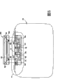
Fig. 1 is a front elevation of implementing sun shield of the present invention and vanity mirror assembly;
Fig. 2 is the top view that expression is shown in an open position the visor body of the Fig. 1 that exposes the sun shield intraware;
Fig. 3 is the front elevation of sun shield shown in Figure 1, wherein removed decorate and with the vanity mirror components apart with explanation with the vanity mirror assembled on visor body;
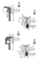
Fig. 4 is the fragmentary, perspective view of the part of the picture frame of vanity mirror assembly and the lid amplification of decomposing;
Fig. 5 is the front elevation that the part of vanity mirror assembly is decomposed, expression lens and mounting structure thereof;
Fig. 6 is the partial elevation view of amplification around structure shown in Figure 5;
Fig. 7 is the section drawing along the amplification of Fig. 1 section line VII-VII intercepting, and expression is covered in the turning cylinder one and locked by lens when installing as shown in Figure 5;
Fig. 8 is along the partial section of the amplification of Fig. 6 section line VIII-VIII intercepting, and one the operation that is in the lid click spring that covers off position is described;
Fig. 9 is the partial section along the amplification of the structure shown in Figure 8 of Fig. 6 section line IX-IX intercepting, and expression lid open position of arrow A indication in Fig. 9 moves;
Figure 10 is the partial section along the amplification of Fig. 6 section line X-X intercepting, and the expression lid is shown in an open position;
Figure 11 is that block is covered in expression along the partial section of the amplification of Fig. 6 section line XI-XI intercepting, and wherein lid is in the closed position;
Figure 12 is that lid is shown in an open position shown in it along the partial section of the amplification of Fig. 6 section line XII-XII intercepting, lid block and picture frame engagement;
Figure 13 is the back view of the amplification of vanity mirror assembly shown in Figure 1;
Figure 14 is the partial section along the amplification of Fig. 6 section line XIV-XIV intercepting, the operation of the axis cam that the electric switch with the vanity mirror assembly moves is described, and described switch is shown in an open position;
Figure 15 is the partial section along the amplification of Fig. 6 section line XV-XV intercepting, the operation of the axis cam that the electric switch with the vanity mirror assembly moves is described, and described switch is in the closed position;
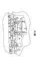
Figure 16 is the fragmentary, perspective view that represents as shown in Figure 3 the vanity mirror parts to be assembled to the amplification of visor core in the visor core process and vanity mirror;
Figure 17 is the partial vertical section drawing of the amplification that is electrically connected of the conductor in vanity mirror circuit and the visor body in the expression fitting process; And
Figure 18 is the vertical cross-section diagram that the vanity mirror assembly has been installed to the amplification of structure shown in Figure 17 after the visor body.
The specific embodiment
At first, represented to embody sun shield 10 of the present invention, and this sun shield 10 comprises illuminated vanity mirror assembly 20 with reference to figure 1.Sun shield 10 also comprises dwang assembly 30, this dwang assembly 30 is used in a conventional manner sun shield being connected to roof so that sun shield is rotating between the curling position of lifting of roof and the use location of putting down around dwang 32, and can turn to the side window position if desired.Sun shield dwang 32 is installed to visor body by torque control and slide assemblies 40, as shown in Figure 2.Slide assemblies 40 is installed in the pipeline 43 and along the bar 42 that is installed in the visor core 54 and slides, so that sun shield also can move adjustably along dwang 32.Described torque and slide assemblies 40 are disclosed in detail in the PCT application No.PCT/US2003/031130 that is called " sliding sun visor " of application on October 1st, 2003.Plate core 50 is covered by the ornament materials 11 that is fit to.Sun shield 10 also comprise in the slot that is releasably attached on the vehicle so that sun shield when needed can be from the front windshield rotated position to the side window position auxiliary sun shield intermediate plate 12.
The vanity mirror assembly 20 that snaps in mechanically and Denso fit in the visor body 50, as shown in Figure 3 and will be discussed in more detail below.Visor body 50 preferably includes the plate core of being made by polymeric material that is fit to such as the molded half plate core 51 and 53 that forms of polypropylene 54. Half plate core 51 and 53 is hinged and fold fixed to one another to form visor body along hinge lines 55 (Fig. 2).Dwang 32 is the hollow pivot rod that wherein accommodate a pair of electric conductor 56 and 58, following described in conjunction with Figure 16 to 18, this is to the insulated electric conductor of electric conductor 56 and 58 for being peeled off by the end of locator protrusions location, so that vanity mirror assembly 20 is electrically connected to provide working power to illuminated vanity mirror assembly 20 mutually with visor core 54.
As shown in Figs. 4-6, picture frame 70 generally includes the rectangular aperture 74 that is positioned at the mirror top, accommodates the cartridge lamp 115 that links to each other with circuit in this opening, and lens 100 extend on this opening when assembling.Described opening comprises the cylindrical pocket that surrounds 76 that is positioned at the one end, and the cylinder slot 78 that is opened wide by bow-shaped part 79 and 81 being used for of forming semicircle that snaps in the longitudinal interval of the turning cylinder 98 that holds lid as described below as shown in Figure 7.Lid 90 comprises first turning cylinder of inwardly giving prominence to 96 of the cylinder opening that extends through slot 76 shown in dotted line B among Fig. 4.When so inserted, from the inwardly outstanding turning cylinder 98 of the opposite edges of the rectangular channel 92 of lid 90 align with slot 78 and inlay card between the elastic leg 79 and 81 of formation slot 78.
By at first the end of minor axis 96 being inserted in the cylinder open of sealing slot 76, and align with turning cylinder 98 between the tapered opening 83 (Fig. 7) of half-cylindrical slot 76, and shift onto downwards on the turning cylinder 98 so that lid is snapped in the slot, thereby make lid 90 be positioned and by kayser in picture frame 70, shown in Fig. 4 to 7.After being positioned in the lamp slot that holds cartridge lamp 115 that is formed by a pair of half-cylindrical electrical contact 117 and 118 (Fig. 4) at interval, lamp 115 carries out this fitting process.When lid had been positioned and snapped in the picture frame, cam 95 and 97 engaged with spring 120 and 122 respectively, and block 91 and 93 engages with locking protrusion 131 and 133.
Described picture frame also comprises the locking protrusion 75 (Fig. 3) of a plurality of separations, and this locking protrusion 75 is installed in the holding tank 25 that forms in the visor core 54 and with vanity mirror assembly 20 and is locked in the holding tank 25, so that vanity mirror assembly 20 is mechanically connected to sun shield.Picture frame 70 also comprises registration mast 77, this registration mast 77 is longer than from the outward extending distance of picture frame and is extended in locking protrusion 75 and the slot visor body 14 27 with convenient alignment and assembling, thereby not only vanity mirror assembly 20 is mechanically connected to visor body 14, and it is as described below, circuit in the picture frame 70 110 is electrically connected to conductor 56,58 in the plate core 54.
Contact 150 shown in Figure 17 and 18 and 160 for make by corrosion-resistant steel with shaping circuit 110 integrally formed spring clips, thereby when being installed to visor body, vanity mirror assembly 20 provides enough pressure, with the stripped end 55 that lockably engages and be fixed to electric conductor 56 and 58 to contact 150 and 160.Shown in Figure 17 and 18, each in the contact 150,160 all comprises first plate 152 and second plate 156 that wherein is formed with U-lag 154, and the 155 and 157 outside polymerizations in the end of described plate.Annular section 158 on the plate 156 extends to the leg that forms groove 154 and engages and extend through groove 154, shown in Figure 16 and 17.
Therefore, system of the present invention provides a kind of vanity mirror parts that have the lid that is stuck and lens and embed molded case circuit, wherein this circuit is interconnected by the vanity mirror assembly is stuck in against the position of visor core, thereby is electrically connected and is mechanically connected to visor core with quick relatively and therefore cheap assembly method.Although in conjunction with sun shield of the present invention illuminated vanity mirror assembly 20 is described, other housing with electric device also can use in conjunction with unique circuit of the present invention the electric device in the housing is electrically connected to mutually the visor body comprising lead.Therefore, be used for Homelink board programmable garage door open the housing that snaps in of projector or memo recorders can machinery and be electrically connected to the sun shield that the visor body of utilizing structure of the present invention has power conductor.
It will be understood by those of skill in the art that under the condition of the spirit and scope of the present invention that do not break away from the claims definition and can make these or other modification preferred implementation of the present invention as described herein.
Claims (12)
1. vanity mirror assembly comprises:
Wherein be fit to hold the picture frame of mirror and be used to illuminate the lamp of described mirror, described picture frame comprise the cylindrical pocket that surrounds and with the half-cylindrical slot that opens wide of the described cylindrical pocket longitudinal interval that surrounds; And
Lid with first turning cylinder and second turning cylinder, wherein said first turning cylinder extends in the described cylindrical pocket that surrounds, and the described second turning cylinder inlay card is in described unlimited half-cylindrical slot;
It is characterized in that described vanity mirror assembly also comprises and be adapted at the lens of inlay card in described picture frame on the described lamp, described lens comprise the edge that engages with described second turning cylinder to keep described lid to engage with described picture frame.
2. illuminated vanity mirror assembly comprises:
Wherein be fit to hold the picture frame of mirror, described picture frame comprises the lamp that is used to illuminate described mirror, described picture frame comprises that the lid near a pair of interval at described picture frame edge holds slot, in the wherein said slot one comprises and is used for the turning cylinder place of capture is remained on wherein cylindrical pocket, and the slot of another slot for opening wide, be used for lid is snapped fitted to described picture frame, described picture frame comprises that also at least one click spring holds slot; And
Comprise being used for that described lid comprises aliging with described click spring and opens and closes the cam of control described lid is carried out interlock at described cylindrical and unlimited groove lids that extend, integrally formed first and second turning cylinders;
It is characterized in that described illuminated vanity mirror assembly also comprises and is connected to described picture frame in the described lid turning cylinder at least one remained on the lens in the described picture frame.
3. assembly as claimed in claim 1 or 2, it is characterized in that, described picture frame by polymeric material molded form and comprise that embedding molded case circuit, wherein said circuit comprise when described vanity mirror assembly is installed to visor core be fit to the contact that engages with the conductor of visor core.
4. as assembly as described in the claim 3, it is characterized in that described circuit also is formed for holding the lamp slot of described lamp.
5. as assembly as described in the claim 3, it is characterized in that described circuit also is formed for holding the lamp slot of lamp.
6. as assembly as described in claim 4 or 5, it is characterized in that described circuit also comprises the switch with deflectable switch contact.
7. as assembly as described in the claim 6, it is characterized in that, one in described first and second turning cylinders of described lid comprises switch cam, when described lid is shown in an open position, described switch cam and described deflectable contact optionally engage activating described switch, thereby provide working power to the lamp that is arranged in described lamp slot.
8. as assembly as described in the claim 7, it is characterized in that described picture frame comprises the lid that at least one engages with spring, and wherein said lid comprises and engages the cam that opens and closes the position optionally described lid is remained on described spring.
9. as assembly as described in the claim 8, it is characterized in that described lid comprises around described lens and makes the groove that described lid can move with respect to described picture frame and lens.
10. as assembly as described in the claim 6, it is characterized in that, a turning cylinder of described lid also comprises switch cam, when described lid is shown in an open position, described switch cam and described deflectable contact optionally engage activating described switch, thereby provide working power to the lamp that is arranged in described lamp slot.
11. sun shield and vanity mirror assembly comprise:
Visor body;
Wherein be fit to hold the picture frame of mirror and hold slot near the lid that described picture frame edge is used for lid is snapped fitted to described picture frame; And
Have first turning cylinder that in described slot, extends and the lid of second turning cylinder;
It is characterized in that, described sun shield and vanity mirror assembly comprise that also being connected to described picture frame is used at least one of described lid turning cylinder remained on lens in the described picture frame, the described slot of wherein said picture frame comprise the cylindrical pocket that surrounds and with the half-cylindrical slot that opens wide of the described slot longitudinal interval that surrounds, wherein said lid is included in first turning cylinder and second turning cylinder of inlay card in described half-cylindrical slot that extends in the described cylindrical pocket that surrounds; And described lens remain on described second turning cylinder in the described half-cylindrical slot.
12. as assembly as described in the claim 11, it is characterized in that, described picture frame comprises the lamp that is used to illuminate described mirror, wherein said picture frame by polymeric material molded form and comprise that embedding molded case circuit, described circuit comprise when described vanity mirror assembly is installed to described visor body be fit to the contact that engages with the contact of described visor body.
Applications Claiming Priority (2)
| Application Number | Priority Date | Filing Date | Title |
|---|---|---|---|
| US42776002P | 2002-11-20 | 2002-11-20 | |
| US60/427,760 | 2002-11-20 |
Related Child Applications (1)
| Application Number | Title | Priority Date | Filing Date |
|---|---|---|---|
| CNA2008101848648A Division CN101423039A (en) | 2002-11-20 | 2003-11-19 | Covered illuminated vanity mirror assembly |
Publications (2)
| Publication Number | Publication Date |
|---|---|
| CN1714011A CN1714011A (en) | 2005-12-28 |
| CN100455460C true CN100455460C (en) | 2009-01-28 |
Family
ID=32326590
Family Applications (2)
| Application Number | Title | Priority Date | Filing Date |
|---|---|---|---|
| CNA2008101848648A Pending CN101423039A (en) | 2002-11-20 | 2003-11-19 | Covered illuminated vanity mirror assembly |
| CNB2003801036087A Expired - Fee Related CN100455460C (en) | 2002-11-20 | 2003-11-19 | Covered illuminated vanity mirror assembly |
Family Applications Before (1)
| Application Number | Title | Priority Date | Filing Date |
|---|---|---|---|
| CNA2008101848648A Pending CN101423039A (en) | 2002-11-20 | 2003-11-19 | Covered illuminated vanity mirror assembly |
Country Status (6)
| Country | Link |
|---|---|
| US (1) | US7311427B2 (en) |
| EP (1) | EP1562786A2 (en) |
| JP (1) | JP2006506275A (en) |
| CN (2) | CN101423039A (en) |
| AU (1) | AU2003295729A1 (en) |
| WO (1) | WO2004045878A2 (en) |
Families Citing this family (19)
| Publication number | Priority date | Publication date | Assignee | Title |
|---|---|---|---|---|
| US8211078B2 (en) | 2005-02-17 | 2012-07-03 | The Procter And Gamble Company | Sanitary napkins capable of taking complex three-dimensional shape in use |
| US9579238B2 (en) | 2005-02-17 | 2017-02-28 | The Procter & Gamble Company | Sanitary napkins capable of taking complex three-dimensional shape in use |
| US20070187976A1 (en) * | 2005-04-01 | 2007-08-16 | Johnson Controls Technology Company | Visor and method for making a visor |
| US7534018B2 (en) | 2007-03-16 | 2009-05-19 | International Automotive Components North America, Inc. | Illuminated visor vanity |
| US20090066109A1 (en) * | 2007-09-12 | 2009-03-12 | Hobson James J | Sun visor vanity assembly |
| US20100094142A1 (en) * | 2008-10-10 | 2010-04-15 | Baoshan Yu | Display Module of LED Light Pillar of Hemomanometer and the Hemomanometer with LED Light Pillar |
| WO2010081030A1 (en) * | 2009-01-09 | 2010-07-15 | Johnson Controls Technology Company | Hinge assembly for vehicle interior trim component |
| US8425094B2 (en) * | 2010-06-09 | 2013-04-23 | Ford Global Technologies, Llc | Vehicle vanity and light assembly and visor having vanity and dome lighting |
| US8556325B2 (en) | 2011-09-20 | 2013-10-15 | Irvin Automotive Products, Inc. | Sliding visor |
| CN103909867B (en) * | 2012-12-30 | 2016-04-27 | 重庆长安汽车股份有限公司 | A kind of automotive sunshade panel vanity mirror |
| US10737559B2 (en) | 2014-12-16 | 2020-08-11 | Irvin Automotive Products, LLC | Visor |
| MX2018008451A (en) * | 2016-01-15 | 2019-01-10 | Irvin Automotive Products Llc | Visor. |
| US20170240103A1 (en) | 2016-02-23 | 2017-08-24 | Motus Integrated Technologies | Vehicle sun visor assembly having an electrical system |
| US10065483B2 (en) | 2016-10-28 | 2018-09-04 | Teraflex, Inc. | Modular sun visor system |
| CN108613131B (en) * | 2016-12-22 | 2024-01-02 | 市光法雷奥(佛山)汽车照明系统有限公司 | Frame device, lighting device and motor vehicle |
| US10688850B2 (en) | 2018-03-13 | 2020-06-23 | Irvin Automotive Products, LLC | Sliding visor |
| US10870337B2 (en) * | 2019-02-28 | 2020-12-22 | Irvin Automotive Products, LLC | Thin visor |
| US10864804B2 (en) | 2019-02-28 | 2020-12-15 | Irvin Automotive Products, LLC | Sliding thin visor |
| CN111361513B (en) * | 2020-04-22 | 2023-07-18 | 宁波福尔达智能科技股份有限公司 | Automobile alarm switch assembly capable of preventing false touch |
Citations (7)
| Publication number | Priority date | Publication date | Assignee | Title |
|---|---|---|---|---|
| US4760503A (en) * | 1986-09-26 | 1988-07-26 | Prince Corporation | Visor for a vehicle |
| US5011211A (en) * | 1988-04-29 | 1991-04-30 | Autopart Sweden Ab | Sun visor for motor vehicles |
| US5117337A (en) * | 1991-01-16 | 1992-05-26 | Koito Manufacturing Co., Ltd. | Vanity mirror |
| JPH0911749A (en) * | 1995-07-01 | 1997-01-14 | Gebr Happich Gmbh | Sunvisor for car |
| JPH10157456A (en) * | 1996-11-23 | 1998-06-16 | Becker Group Europ Gmbh | Sunvisor for vehicle |
| CN2380422Y (en) * | 1999-04-20 | 2000-05-31 | 杨奋雄 | Light-shielding board |
| US6435593B2 (en) * | 2000-04-05 | 2002-08-20 | Johnson Controls Technology Company | Visor for vehicles |
Family Cites Families (14)
| Publication number | Priority date | Publication date | Assignee | Title |
|---|---|---|---|---|
| US4213169A (en) * | 1978-11-09 | 1980-07-15 | Prince Corporation | Covered visor mirror |
| US4491899A (en) * | 1983-02-07 | 1985-01-01 | Prince Corporation | Visor cover assembly |
| US5078445A (en) * | 1986-09-26 | 1992-01-07 | Prince Corporation | Visor |
| US4866579A (en) | 1988-05-23 | 1989-09-12 | Prince Corporation | Snap-in mirror package |
| US5267090A (en) * | 1988-10-14 | 1993-11-30 | United Technologies Automotive, Inc. | Automobile sun visor vanity mirror module |
| US4997228A (en) * | 1989-07-24 | 1991-03-05 | Prince Corporation | Multiple function visor |
| US5098150A (en) * | 1990-12-27 | 1992-03-24 | Prince Corporation | Visor cover hinge |
| US5331518A (en) * | 1992-09-22 | 1994-07-19 | Prince Corporation | Visor mirror cover assembly |
| DE19523067A1 (en) * | 1994-08-02 | 1996-02-08 | Happich Gmbh Gebr | Sun visor used in motor vehicle |
| US5685629A (en) * | 1994-09-29 | 1997-11-11 | Prince Corporation | Vanity mirror assembly |
| US5716092A (en) * | 1996-06-11 | 1998-02-10 | Prince Corporation | Visor and method of manufacturing |
| US5866579A (en) * | 1997-04-11 | 1999-02-02 | Synaptic Pharmaceutical Corporation | Imidazole and imidazoline derivatives and uses thereof |
| US6012757A (en) * | 1998-07-24 | 2000-01-11 | Becker Group Europe Gmbh | Sun visor for vehicles |
| KR20010001742U (en) * | 1999-06-30 | 2001-01-26 | 류정열 | Vanity Mirror Structure of Sun Screen for Vehicles |
-
2003
- 2003-11-19 EP EP03786932A patent/EP1562786A2/en not_active Withdrawn
- 2003-11-19 US US10/535,503 patent/US7311427B2/en not_active Expired - Fee Related
- 2003-11-19 JP JP2004553992A patent/JP2006506275A/en active Pending
- 2003-11-19 CN CNA2008101848648A patent/CN101423039A/en active Pending
- 2003-11-19 CN CNB2003801036087A patent/CN100455460C/en not_active Expired - Fee Related
- 2003-11-19 WO PCT/US2003/037196 patent/WO2004045878A2/en active Application Filing
- 2003-11-19 AU AU2003295729A patent/AU2003295729A1/en not_active Abandoned
Patent Citations (7)
| Publication number | Priority date | Publication date | Assignee | Title |
|---|---|---|---|---|
| US4760503A (en) * | 1986-09-26 | 1988-07-26 | Prince Corporation | Visor for a vehicle |
| US5011211A (en) * | 1988-04-29 | 1991-04-30 | Autopart Sweden Ab | Sun visor for motor vehicles |
| US5117337A (en) * | 1991-01-16 | 1992-05-26 | Koito Manufacturing Co., Ltd. | Vanity mirror |
| JPH0911749A (en) * | 1995-07-01 | 1997-01-14 | Gebr Happich Gmbh | Sunvisor for car |
| JPH10157456A (en) * | 1996-11-23 | 1998-06-16 | Becker Group Europ Gmbh | Sunvisor for vehicle |
| CN2380422Y (en) * | 1999-04-20 | 2000-05-31 | 杨奋雄 | Light-shielding board |
| US6435593B2 (en) * | 2000-04-05 | 2002-08-20 | Johnson Controls Technology Company | Visor for vehicles |
Non-Patent Citations (1)
| Title |
|---|
| 6235527B1 2001.12.04 |
Also Published As
| Publication number | Publication date |
|---|---|
| WO2004045878A2 (en) | 2004-06-03 |
| WO2004045878B1 (en) | 2005-07-28 |
| EP1562786A2 (en) | 2005-08-17 |
| US20060098446A1 (en) | 2006-05-11 |
| WO2004045878A3 (en) | 2004-12-16 |
| JP2006506275A (en) | 2006-02-23 |
| CN1714011A (en) | 2005-12-28 |
| US7311427B2 (en) | 2007-12-25 |
| AU2003295729A1 (en) | 2004-06-15 |
| AU2003295729A8 (en) | 2004-06-15 |
| CN101423039A (en) | 2009-05-06 |
Similar Documents
| Publication | Publication Date | Title |
|---|---|---|
| CN100455460C (en) | Covered illuminated vanity mirror assembly | |
| CA1299612C (en) | Visor | |
| US4967046A (en) | Automotive contact switch arrangement with essentially planar switch springs | |
| GB1575086A (en) | Sun visor assembly for vehicles | |
| US5331518A (en) | Visor mirror cover assembly | |
| CN107411249A (en) | Engaging support mechanism for watch band | |
| US6444930B1 (en) | Environmentally sealed rocker switch | |
| US5078445A (en) | Visor | |
| JPH0159124B2 (en) | ||
| JP2006506275A5 (en) | ||
| JPH06290836A (en) | Charging connector for electric vehicle | |
| US4237353A (en) | Telescopic spring operable as an electric switch | |
| WO2021071704A1 (en) | Charging or refuelling recess | |
| US20080074866A1 (en) | Visor vanity | |
| US5821490A (en) | Push button switch module | |
| JP2654361B2 (en) | Sun visor for vehicles | |
| EP0413308B1 (en) | A construction assembly including a telescopic strut | |
| US20030168881A1 (en) | Lock control assembly for a motor vehicle opening panel and opening panel equipped with same | |
| US7217017B2 (en) | Vanity for a vehicle | |
| WO1996009939B1 (en) | Illuminated vanity mirror assembly for a vehicular sun visor | |
| KR100478588B1 (en) | Fixed structure of room lamp | |
| CA2017336C (en) | Multiple contact switch arrangement | |
| KR200263755Y1 (en) | Slide type sun visor having a illuminator | |
| CA3010309C (en) | Visor | |
| CN211442124U (en) | Mounting structure of decorative lamp connector and skylight device |
Legal Events
| Date | Code | Title | Description |
|---|---|---|---|
| C06 | Publication | ||
| PB01 | Publication | ||
| C10 | Entry into substantive examination | ||
| SE01 | Entry into force of request for substantive examination | ||
| C14 | Grant of patent or utility model | ||
| GR01 | Patent grant | ||
| C17 | Cessation of patent right | ||
| CF01 | Termination of patent right due to non-payment of annual fee |
Granted publication date: 20090128 Termination date: 20091221 |