CN100453947C - Plate-shell heat exchanger - Google Patents
Plate-shell heat exchanger Download PDFInfo
- Publication number
- CN100453947C CN100453947C CNB2007101228123A CN200710122812A CN100453947C CN 100453947 C CN100453947 C CN 100453947C CN B2007101228123 A CNB2007101228123 A CN B2007101228123A CN 200710122812 A CN200710122812 A CN 200710122812A CN 100453947 C CN100453947 C CN 100453947C
- Authority
- CN
- China
- Prior art keywords
- plate
- shell
- runner
- shell side
- tube
- Prior art date
- Legal status (The legal status is an assumption and is not a legal conclusion. Google has not performed a legal analysis and makes no representation as to the accuracy of the status listed.)
- Active
Links
Images



Abstract
This invention discloses a board shell type heat interchanger, its main package loam board tube control, shell, tube Cheng Yuke regulation import and export; States the board tube control by the stack-up to combine in the together compound flow channel ripple slab composes, in each piece of slab plane arranges in turn has V shape concavity ripple trough, states the ripple trough according to assume the mutually perpendicular neighboring, and two kind of different orientation's ripple trough vertical side becomes an acute angle separately with slab two orientation, states slab, reverse side relative combination, forms the mutually perpendicular in its neighboring two interior, and gap heat transfer tube Cheng Heke regulation two kind of compound flow channels; States the tube regulation flow channel both sides through to pass in and out the oral siphon box and the belt separately inflates the festival the export to connect; States the shell regulation both sides to connect separately with the shell regulation import and export. This invention has at the same time the disc heat interchanger heat transfer efficiency to be high, compact is good and the shell type heat interchanger sturdy construction the merit, simultaneously it has overcome former disc heat interchanger bearing pressure ability difference and the shell type heat interchanger heat transfer efficiency is low and structure huge shortcoming.
Description
Technical field
The present invention relates to a kind of heat-exchange apparatus, particularly be used for two kinds of equipment that fluid media (medium) carries out heat exchange in fields such as petroleum refining, chemical industry, electric power, metallurgy.
Background technology
The used heat-transfer pipe of present shell-and-tube heat exchanger is circular pipe.According to national standard, the most frequently used pipe diameter of shell-and-tube heat exchanger is two kinds of 25mm and 19mm.The advantage of this heat exchanger is that firm in structure, elasticity is big, shortcoming is that heat transfer efficiency is low, compactedness is poor, and shared space is bigger.In addition, occurred a kind of lamella heat exchanger in recent years, its feature is that higher compactedness and heat transfer efficiency are arranged, but that its shortcoming is the bellows-shaped of plate is single, and heat transfer coefficient is not high.Its bearing capacity is also poor simultaneously, therefore fails to obtain large scale application.
Summary of the invention
The purpose of this invention is to provide a kind of lamella heat exchanger, poor with the bearing capacity that the plate type heat exchanger that solves in the past exists, heat transfer efficiency is low, structure is huge and technical problem such as less robust.
A kind of lamella heat exchanger of the present invention, it mainly comprises, and the tube bank of plate pipe, housing, tube side are imported and exported, shell side is imported and exported and bearing; Described plate pipe tube bank is made up of the stacked compound runner corrugated cardboard sheet of combining, be aligned in sequence with V-arrangement concavity wave groove on the every plate plane, described wave groove is wave grooves orthogonal and that two kinds of different directions are arranged and becomes the direction of an acute angle to arrange respectively with two vertical edges of plate by adjacent, after described plate makes up relatively by positive and negative, form tube side and two kinds of compound runners of shell side vertical mutually and that conduct heat at interval in the inside of its adjacent two layers; Described tube side runner is the runner that its two ends are connected with import bobbin carriage, outlet bobbin carriage respectively, and described outlet bobbin carriage is communicated with the outlet of band expansion joint; Described shell side runner be it two ends respectively with housing on shell side import and export the runner be connected.
Aforesaid a kind of lamella heat exchanger, described shell side has the baffling structure, described baffling structure is the totally-enclosed structure, several deflection plates are set in shell side, constitute guide shell with the deflection plate of circular blast baffle and both sides, the port closed of two neighboring sections shell side is become to have the described baffling structure of import and export, set gradually the guide shell that deflection plate and arc plate constitute in a manner described, every section shell side runner is joined end to end, to form a shell side runner with complete baffling form.
Aforesaid a kind of lamella heat exchanger, described wave groove are V-type, and are provided with a flow-disturbing groove in the central authorities that adjacent V-type groove is surrounded.
A kind of lamella heat exchanger of the present invention has plate type heat exchanger heat transfer efficiency height concurrently, the advantage that compactedness is good and shell-and-tube heat exchanger is firm in structure, it has overcome plate type heat exchanger bearing capacity difference and the low huge shortcoming of structure that reaches of shell-and-tube heat exchanger heat transfer efficiency in the past again simultaneously.The comparable common tube shell heat exchanger of its heat transfer coefficient improves more than 25% under identical process conditions, and base is to one times, and its heat transfer area is higher more than 50% than common tube shell-type under identical volume.Adopt heat exchanger of the present invention to reduce investment outlay significantly and to take up room, it is a kind of heat transmission equipment of high-efficiency compact.
In the heat transfer process of the deep fat of certain oil refining apparatus and cold oil, the treating capacity of deep fat is that the 95000t/h temperature is as cold as 65 ℃ with 150 ℃; The temperature of cold oil rises to 119 ℃ from 30 ℃.Thermic load 4968600W.Under same process conditions, adopt the comparative result of two types of heat exchangers to see attached list 1.
As known from Table 1, adopt the heat transfer coefficient of heat exchanger of the present invention can improve 30%, compactedness greatly improves, and is all the heat exchanger of diameter 700mm, and the heat transfer area of shell-and-tube is 135m
2, and the area of heat exchanger of the present invention is 202m
2Hence one can see that adopts heat exchanger of the present invention can save occupation of land space and investment significantly.
In addition, plate type heat exchanger reaches purpose of energy saving because the particularity of runner just can obtain higher heat transfer coefficient at low reynolds number, thereby can operate, thereby fall operating cost under lower speed.Original tube side and shell side flow velocity as a certain design are respectively 1.45m/s and 0.48m/s; And the present invention only is 0.3m/s and 0.2m/s.Intrinsic total pressure drop tube side is 0.348MPa, shell side 0.147MPa; Pressure drop tube side of the present invention only has 0.06MPa, and shell side only has 0.045MPa.Driving power originally is 20.26KW, and driving power of the present invention is 2.6KW, and by 0.5 yuan of calculating of every degree electricity, year can be saved 7.4 ten thousand yuan.
Description of drawings
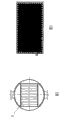
Fig. 1 is a heat exchanger structure cutaway view of the present invention.
Fig. 2 be Fig. 1 along A-A direction cutaway view.
Fig. 3 is the plate face structural representation of plate of the present invention.
Fig. 4 is the partial enlarged drawing of Fig. 3.
Fig. 5 is the profile along the C-C direction of Fig. 4.
Fig. 6 is the sectional structure chart of plate pipe of the present invention.
Fig. 7 is the cross section structure figure of plate pipe tube bank of the present invention.
Fig. 8 is the baffling structural representation of shell side guide shell of the present invention.
The specific embodiment
Specific embodiments of the invention are referring to accompanying drawing.The structure chart of Fig. 1 has reflected the general assembly drawing of lamella heat exchanger.This lamella heat exchanger has a housing 4, and these housing 4 two ends are housing left and right sides end socket 2,11.At two ends, housing 4 left and right sides is tube side import 1 and tube side outlet 10, and they are connected with the tube side runner two ends of plate pipe tube bank 5 with tube side outlet bobbin carriage 8 by expansion joint 9 respectively.Press the custom appellation of heat exchanger, will be called tube side with the runner of housing shaft line parallel.The outlet bobbin carriage of tube side is that tube bank can freely be stretched in housing by expansion joint plate pipe with the purpose that the outlet of a band expansion joint links to each other.Be respectively equipped with shell side at the two ends, the left and right sides of housing 4 sides and import and export 12,3.The runner of described shell side 4 is a multistage baffling structure, by deflection plate 6 and circular blast baffle 7 every section shell side runner is isolated, and forms a deflector type shell side runner that is arranged in order.Deflector type shell side runner two ends are imported and exported 12,3 with the shell side on the described housing 4 and are connected respectively.Be provided with two bearings 13 in housing 4 lower ends.Described housing 4 can adopt the tube structure of circular section as shown in Figure 2.In Fig. 1, along the axis direction of cylindrical shell, placing plate pipe tube bank 5.Tube bank is made of plate 14 stacks, and in tube bank 5, the horizontal direction runner is the tube side runner, and the vertical direction runner is the shell side runner.
The structure of each laminate sheet 14 of formation plate pipe tube bank is referring to shown in Fig. 3,4.Plate 14 back sides are provided with the vertical mutually concavity wave groove of proper alignment successively, the wave groove of two kinds of different directions arrangements becomes the direction of an acute angle to arrange respectively with two vertical edges of plate, each concavity wave groove is a V-arrangement, and the V-arrangement face of described concavity wave groove can be smooth surface.Owing to be the plate Facad structure shown in Fig. 3,4, so the wave groove shown in the figure is the convex structure.In order to increase turbulent effect, four plate centre that wave groove surrounded adjacent are provided with a flow-disturbing groove.
The cross sectional shape of above-mentioned plate can be referring to the structure shown in Fig. 5.As can be seen from the figure, a flow-disturbing groove 14-1 is arranged on the plate between two wave groove 14-2.
Will be by the plate shown in Fig. 3,4,5, after pressing the corresponding combination of positive and negative, between two plates, can form cross sectional shape as shown in Figure 6 with fluid passage, the runner that forms at the adjacent two layers plate is crisscross combined type runner, that is to say at longitudinal direction and all can form as shown in Figure 6 flow passage structure in a lateral direction.To be defined as the tube side runner with the runner of housing shaft line parallel, the runner of other direction is the shell side runner.Superpose in a manner described by the multilayer plate and just to have formed the cross section structure of plate pipe tube bank as shown in Figure 7.The compound runner effect that plate tube bank shown in Fig. 7 forms has three: one, increases runner inner fluid turbulence level, further augmentation of heat transfer; The 2nd, the anti-pressure ability of increase plate pipe, the 3rd, the automatic cleaning action in fluid convection road is facilitated in the alternation cross section of runner.
The present invention has higher heat transfer efficiency in order to keep heat exchanger, and shell side has also adopted does not have the baffling of leakage technology.The seal member that described nothing leakage baffling technology relates to comprises: the guide shell that deflection plate and circular arc plate constitute, their structure can be referring to Fig. 8.Shell side runner segmentation with the tube bank of plate pipe, two-port place at each section shell side runner, deflection plate 6 with circular blast baffle 7 and both sides seals respectively, so that the flow passage structure that two neighboring sections shell side runner can have the baffling form, set gradually the guide shell that deflection plate and circular arc plate constitute in a manner described, every section shell side runner is joined end to end, to form a shell side runner with complete baffling form.
The optimum specifications parameter of plate tube sheet sheet of the present invention is as follows:
The width of plate pipe: 200mm to 2000mm
The length of plate pipe: 300mm to 30000mm
The wave height of plate ripple: 1 to 8mm
The pitch of waves of plate ripple: 12 to 80mm
The length of plate ripple: 8 to 60mm
The width of plate ripple: 8 to 60mm
Table 1:
| Heat exchanger types | Diameter of the housing/mm | Separate unit area/m 2 | Heat transfer coefficient/W/ (m 2.K) | Reference area/m 2 | Select the platform number for use |
| The standard pipe shell-type | 700 | 135 | 257 | 572 | 5 |
| The present invention | 700 | 202 | 353 | 410 | 3 |
Claims (3)
1, a kind of lamella heat exchanger, it mainly comprises, and the tube bank of plate pipe, housing, tube side are imported and exported, shell side is imported and exported and bearing; It is characterized in that: described plate pipe tube bank is made up of the stacked compound runner corrugated cardboard sheet of combining, be aligned in sequence with V-arrangement concavity wave groove on the every plate plane, described wave groove is wave grooves orthogonal and that two kinds of different directions are arranged and becomes the direction of an acute angle to arrange respectively with two vertical edges of plate by adjacent, after described plate makes up relatively by positive and negative, form tube side and two kinds of compound runners of shell side vertical mutually and that conduct heat at interval in the inside of its adjacent two layers; Described tube side runner is the runner that its two ends are connected with import bobbin carriage, outlet bobbin carriage respectively, and described outlet bobbin carriage is communicated with the outlet of band expansion joint; Described shell side runner be it two ends respectively with housing on shell side import and export the runner be connected.
2, a kind of lamella heat exchanger as claimed in claim 1, it is characterized in that: described shell side has the baffling structure, described baffling structure is the totally-enclosed structure, several deflection plates are set in shell side, deflection plate with circular blast baffle and both sides constitutes guide shell, the port closed of two neighboring sections shell side is become to have the described baffling structure of import and export, set gradually the guide shell that deflection plate and arc plate constitute in a manner described, every section shell side runner is joined end to end, to form a shell side runner with complete baffling form.
3, a kind of lamella heat exchanger as claimed in claim 1 is characterized in that: described wave groove is a V-type, and is provided with a flow-disturbing groove in the central authorities that adjacent V-type groove is surrounded.
Priority Applications (1)
| Application Number | Priority Date | Filing Date | Title |
|---|---|---|---|
| CNB2007101228123A CN100453947C (en) | 2007-07-04 | 2007-07-04 | Plate-shell heat exchanger |
Applications Claiming Priority (1)
| Application Number | Priority Date | Filing Date | Title |
|---|---|---|---|
| CNB2007101228123A CN100453947C (en) | 2007-07-04 | 2007-07-04 | Plate-shell heat exchanger |
Publications (2)
| Publication Number | Publication Date |
|---|---|
| CN101071046A CN101071046A (en) | 2007-11-14 |
| CN100453947C true CN100453947C (en) | 2009-01-21 |
Family
ID=38898384
Family Applications (1)
| Application Number | Title | Priority Date | Filing Date |
|---|---|---|---|
| CNB2007101228123A Active CN100453947C (en) | 2007-07-04 | 2007-07-04 | Plate-shell heat exchanger |
Country Status (1)
| Country | Link |
|---|---|
| CN (1) | CN100453947C (en) |
Families Citing this family (4)
| Publication number | Priority date | Publication date | Assignee | Title |
|---|---|---|---|---|
| DE102007060291B4 (en) * | 2007-12-12 | 2011-04-28 | Sartorius Stedim Biotech Gmbh | Container arrangement with a container with flexible wall |
| FI124763B (en) | 2013-04-04 | 2015-01-15 | Vahterus Oy | Plate heat exchanger and method for constructing multiple passages in a plate heat exchanger |
| CN105091634A (en) * | 2014-05-21 | 2015-11-25 | 航天长征化学工程股份有限公司 | Baffle rod type heat exchanger with built-in expansion joint |
| CN108871017B (en) * | 2018-05-16 | 2020-09-08 | 中国石油大学(华东) | Absorption type all-welded plate-shell heat exchanger |
Citations (6)
| Publication number | Priority date | Publication date | Assignee | Title |
|---|---|---|---|---|
| JPH06229695A (en) * | 1993-02-03 | 1994-08-19 | Tadao Totsuka | Heat exchanger and heat exchanger element |
| JPH07305984A (en) * | 1994-05-10 | 1995-11-21 | Hitachi Ltd | Heat exchanger |
| CN2419564Y (en) * | 2000-05-09 | 2001-02-14 | 杨靖 | Heat exchanger with welded shell |
| CN2462338Y (en) * | 2000-12-20 | 2001-11-28 | 四平市巨元换热设备有限公司 | Multiple composite plates shell type heat exchanger |
| CN2535754Y (en) * | 2002-04-24 | 2003-02-12 | 吴忠福 | Tube-plate type heat-exchanger |
| CN1884951A (en) * | 2005-06-20 | 2006-12-27 | 张延丰 | Plate-shell type heat exchanger |
-
2007
- 2007-07-04 CN CNB2007101228123A patent/CN100453947C/en active Active
Patent Citations (6)
| Publication number | Priority date | Publication date | Assignee | Title |
|---|---|---|---|---|
| JPH06229695A (en) * | 1993-02-03 | 1994-08-19 | Tadao Totsuka | Heat exchanger and heat exchanger element |
| JPH07305984A (en) * | 1994-05-10 | 1995-11-21 | Hitachi Ltd | Heat exchanger |
| CN2419564Y (en) * | 2000-05-09 | 2001-02-14 | 杨靖 | Heat exchanger with welded shell |
| CN2462338Y (en) * | 2000-12-20 | 2001-11-28 | 四平市巨元换热设备有限公司 | Multiple composite plates shell type heat exchanger |
| CN2535754Y (en) * | 2002-04-24 | 2003-02-12 | 吴忠福 | Tube-plate type heat-exchanger |
| CN1884951A (en) * | 2005-06-20 | 2006-12-27 | 张延丰 | Plate-shell type heat exchanger |
Also Published As
| Publication number | Publication date |
|---|---|
| CN101071046A (en) | 2007-11-14 |
Similar Documents
| Publication | Publication Date | Title |
|---|---|---|
| CN101551207B (en) | Shell-and-tube heat exchanger with oblate tube | |
| CN104896977A (en) | Integrated primary surface micro-channel compact heat exchanger | |
| CN111707115A (en) | Diffusion welding compact heat exchanger with combined heat exchange plate | |
| CN100453947C (en) | Plate-shell heat exchanger | |
| CN103868394A (en) | Circulation board of heat exchanger, heat exchanging unit of heat exchanger and heat exchanger | |
| CN101435668A (en) | Internal and external fin flat tube heat exchanger | |
| CN201449186U (en) | Inner/outer spiral fin type cross-flow heat exchanger of heat transferring pipe | |
| CN101696862B (en) | Full welded plate bundle with reinforced structures | |
| CN201081568Y (en) | Lamella heat exchanger | |
| WO2023208129A1 (en) | Microchannel heat exchanger group and air conditioning system having same | |
| WO2015055122A1 (en) | Plated pipe-type heat exchanger | |
| CN201413066Y (en) | Shell-and-tube helix flat tube heat exchanger | |
| CN204535515U (en) | A kind of fin-type heat exchange unit and the heat exchanger containing this unit | |
| CN114688900B (en) | Multi-module combined plate-fin heat exchanger | |
| CN203595441U (en) | Plate tubular corrugated plate bundle | |
| CN210833173U (en) | Heat exchanger plate bundle for phase change heat exchange | |
| CN212378563U (en) | Corrugated plate gas-gas heat exchanger | |
| CN201297878Y (en) | An inside and outside fin flat tube heat exchanger | |
| CN110530179B (en) | Symmetrical bubbling type plate heat transfer element | |
| CN1815124A (en) | Scroll variable heat exchanger | |
| CN103575149B (en) | A kind of band-tube type corrugated board cluster | |
| CN207866058U (en) | A kind of tubular heat exchanger | |
| CN205192299U (en) | Novel all -welded lamella heat exchanger | |
| CN214891965U (en) | Novel integrated double-row micro-channel flat tube | |
| CN110822952A (en) | Four-tube-pass heat exchanger arranged in inclined mode |
Legal Events
| Date | Code | Title | Description |
|---|---|---|---|
| C06 | Publication | ||
| PB01 | Publication | ||
| C10 | Entry into substantive examination | ||
| SE01 | Entry into force of request for substantive examination | ||
| C14 | Grant of patent or utility model | ||
| GR01 | Patent grant | ||
| EE01 | Entry into force of recordation of patent licensing contract |
Assignee: Beijing JInghai Hengtong Chemical Equipment Co., Ltd. Assignor: Beijing Jinghai heat exchanger equipment manufacturing limited liability company | Lai Zhouping Contract record no.: 2010110000064 Denomination of invention: Plate-shell heat exchanger Granted publication date: 20090121 License type: Exclusive License Open date: 20071114 Record date: 20100609 |