CN100451675C - Radar apparatus - Google Patents
Radar apparatus Download PDFInfo
- Publication number
- CN100451675C CN100451675C CNB2005100719909A CN200510071990A CN100451675C CN 100451675 C CN100451675 C CN 100451675C CN B2005100719909 A CNB2005100719909 A CN B2005100719909A CN 200510071990 A CN200510071990 A CN 200510071990A CN 100451675 C CN100451675 C CN 100451675C
- Authority
- CN
- China
- Prior art keywords
- antenna
- received signal
- radar installations
- antennas
- receiving
- Prior art date
- Legal status (The legal status is an assumption and is not a legal conclusion. Google has not performed a legal analysis and makes no representation as to the accuracy of the status listed.)
- Expired - Fee Related
Links
Images


Classifications
-
- H—ELECTRICITY
- H04—ELECTRIC COMMUNICATION TECHNIQUE
- H04B—TRANSMISSION
- H04B7/00—Radio transmission systems, i.e. using radiation field
- H04B7/02—Diversity systems; Multi-antenna system, i.e. transmission or reception using multiple antennas
- H04B7/04—Diversity systems; Multi-antenna system, i.e. transmission or reception using multiple antennas using two or more spaced independent antennas
- H04B7/06—Diversity systems; Multi-antenna system, i.e. transmission or reception using multiple antennas using two or more spaced independent antennas at the transmitting station
- H04B7/0602—Diversity systems; Multi-antenna system, i.e. transmission or reception using multiple antennas using two or more spaced independent antennas at the transmitting station using antenna switching
- H04B7/0604—Diversity systems; Multi-antenna system, i.e. transmission or reception using multiple antennas using two or more spaced independent antennas at the transmitting station using antenna switching with predefined switching scheme
- H04B7/0606—Random or pseudo-random switching scheme
-
- G—PHYSICS
- G01—MEASURING; TESTING
- G01S—RADIO DIRECTION-FINDING; RADIO NAVIGATION; DETERMINING DISTANCE OR VELOCITY BY USE OF RADIO WAVES; LOCATING OR PRESENCE-DETECTING BY USE OF THE REFLECTION OR RERADIATION OF RADIO WAVES; ANALOGOUS ARRANGEMENTS USING OTHER WAVES
- G01S7/00—Details of systems according to groups G01S13/00, G01S15/00, G01S17/00
- G01S7/02—Details of systems according to groups G01S13/00, G01S15/00, G01S17/00 of systems according to group G01S13/00
- G01S7/03—Details of HF subsystems specially adapted therefor, e.g. common to transmitter and receiver
- G01S7/034—Duplexers
-
- H—ELECTRICITY
- H01—ELECTRIC ELEMENTS
- H01Q—ANTENNAS, i.e. RADIO AERIALS
- H01Q3/00—Arrangements for changing or varying the orientation or the shape of the directional pattern of the waves radiated from an antenna or antenna system
- H01Q3/24—Arrangements for changing or varying the orientation or the shape of the directional pattern of the waves radiated from an antenna or antenna system varying the orientation by switching energy from one active radiating element to another, e.g. for beam switching
-
- H—ELECTRICITY
- H01—ELECTRIC ELEMENTS
- H01Q—ANTENNAS, i.e. RADIO AERIALS
- H01Q3/00—Arrangements for changing or varying the orientation or the shape of the directional pattern of the waves radiated from an antenna or antenna system
- H01Q3/26—Arrangements for changing or varying the orientation or the shape of the directional pattern of the waves radiated from an antenna or antenna system varying the relative phase or relative amplitude of energisation between two or more active radiating elements; varying the distribution of energy across a radiating aperture
-
- H—ELECTRICITY
- H04—ELECTRIC COMMUNICATION TECHNIQUE
- H04B—TRANSMISSION
- H04B7/00—Radio transmission systems, i.e. using radiation field
- H04B7/02—Diversity systems; Multi-antenna system, i.e. transmission or reception using multiple antennas
- H04B7/04—Diversity systems; Multi-antenna system, i.e. transmission or reception using multiple antennas using two or more spaced independent antennas
- H04B7/08—Diversity systems; Multi-antenna system, i.e. transmission or reception using multiple antennas using two or more spaced independent antennas at the receiving station
- H04B7/0802—Diversity systems; Multi-antenna system, i.e. transmission or reception using multiple antennas using two or more spaced independent antennas at the receiving station using antenna selection
- H04B7/0805—Diversity systems; Multi-antenna system, i.e. transmission or reception using multiple antennas using two or more spaced independent antennas at the receiving station using antenna selection with single receiver and antenna switching
- H04B7/0814—Diversity systems; Multi-antenna system, i.e. transmission or reception using multiple antennas using two or more spaced independent antennas at the receiving station using antenna selection with single receiver and antenna switching based on current reception conditions, e.g. switching to different antenna when signal level is below threshold
-
- G—PHYSICS
- G01—MEASURING; TESTING
- G01S—RADIO DIRECTION-FINDING; RADIO NAVIGATION; DETERMINING DISTANCE OR VELOCITY BY USE OF RADIO WAVES; LOCATING OR PRESENCE-DETECTING BY USE OF THE REFLECTION OR RERADIATION OF RADIO WAVES; ANALOGOUS ARRANGEMENTS USING OTHER WAVES
- G01S13/00—Systems using the reflection or reradiation of radio waves, e.g. radar systems; Analogous systems using reflection or reradiation of waves whose nature or wavelength is irrelevant or unspecified
- G01S13/02—Systems using reflection of radio waves, e.g. primary radar systems; Analogous systems
- G01S13/06—Systems determining position data of a target
- G01S13/08—Systems for measuring distance only
- G01S13/32—Systems for measuring distance only using transmission of continuous waves, whether amplitude-, frequency-, or phase-modulated, or unmodulated
- G01S13/34—Systems for measuring distance only using transmission of continuous waves, whether amplitude-, frequency-, or phase-modulated, or unmodulated using transmission of continuous, frequency-modulated waves while heterodyning the received signal, or a signal derived therefrom, with a locally-generated signal related to the contemporaneously transmitted signal
- G01S13/345—Systems for measuring distance only using transmission of continuous waves, whether amplitude-, frequency-, or phase-modulated, or unmodulated using transmission of continuous, frequency-modulated waves while heterodyning the received signal, or a signal derived therefrom, with a locally-generated signal related to the contemporaneously transmitted signal using triangular modulation
Abstract
The present invention relates to a radar apparatus that forms multiple digital beams based on reflected waves of a transmitted radiowave. A transmit signal is transmitted in a predetermined cycle from one of transmitting/receiving antennas A1 to A4 arrayed in a row. The antennas A1 to A4, each switched between transmission and reception, are arranged such that the ratio of the spacing between one pair of adjacent antennas to the spacing between the other pair of adjacent antennas is 1:2. The reflected waves are received by the respective antennas, and DBF is performed based on the resulting received signals. Eleven-channel DBF is achieved using the four antennas with a space equivalent to six antennas. By achieving multiple channels with a minimum number of antennas, the size and cost of the apparatus can be reduced while also reducing the processing time and thus enhancing the performance.
Description
The cross reference of related application
The present invention advocates that the application number of submitting on June 21st, 2004 is the right of priority of the Japanese patent application of 2004-182537.
Technical field
The present invention relates to the radar installations of a kind of use Continuous Wave with frequency modulation (FW-CW), more particularly, relate to a kind of digital beam that utilizes and form the radar installations that (DBF) scans the reflection wave of the radiowave of being launched with reception as transmitted wave.
Background technology
This class utilizes DBF to receive the radar installations of scanning, has obtained exploitation in the prior art and for known to the public.In general, the basic structure of such radar installations has been used single emitting antenna and a plurality of receiving antenna, and radiowave is gone out from transmission antennas transmit, and the reflection wave of the radiowave of this emission is received by described a plurality of antennas.
Yet, the radar installations of this structure need with the receiver of receiving antenna as much, and if improve the scanning degree of accuracy, must a large amount of receiver of configuration.This just problem occurred, and along with the increase of receiver number, the weight and the size of described device also increase, and needs very big power.
For addressing the above problem, the radar installations of various reduction weight and size has been proposed, for example, do not examine Jap.P. open S63-256879, H11-311668 and H11-160423.These radar installationss are constructed to make a plurality of receiving antennas to be connected to single receiver via switch.Perhaps, a plurality of receiving antennas are divided into several groups, promptly, for example, the receiving antenna array that comprises a plurality of receiving antennas is divided into subarray, each subarray has four receiving antennas, and for the subarray of each four receiving antenna provides a receiver, these four receiving antennas are connected to described receiver via switch.When receiving the reflection wave of the radiowave of launching, order is switched described a plurality of antenna to be connected with described receiver.Like this, the radar signal of each receiving antenna reception can obtain with time division way.
Utilize this structure, the number of receiver can reduce to one or be less than the number of receiving antenna, thereby has reduced described device size and cost.
Herein, the used radiowave of described radar installations is at the radiowave such as the high frequency band of 76GHz frequency band.Therefore, the signal of carrying at the transmission path from described receiving antenna to described receiver also is a high-frequency band signals.The number of the input signal on the switch that can switch this high-frequency signal normally two or three.
Therefore, when when switching between four or the more receiving antenna, use a plurality of switchs in the practice.For example, the hilted broadsword of respectively doing for oneself is two puts the unit switch that (SPDT) or hilted broadsword three are put (SP3T) switch, realizes switch with tree-shaped combination more.Herein, the high-frequency switcher of planar circuit type, for example, Monolithic Microwave Integrated Circuit (MMIC) or hydrid integrated circuit (HIC) are used as described unit switch.
Yet when the multistage connection of described switch, signal attenuation also whenever increases by a switch along with this signal, and therefore causes such problem, owing to increasing the switching device cascade connection number in order to reduce receiver quantity, causes receiving sensitivity to reduce.
Consider described situation, proposed on the structure simple relatively and can prevent the radar installations that receiving sensitivity reduces, for example, referring to the open 2000-155171 of unexamined Jap.P..When radar installations comprises single emitting antenna and a plurality of receiving antenna as described before, the radar installations that discloses in this patent documentation has used a plurality of emitting antennas, it switch to be used one by one, thereby reduces receiving antenna and the number of the switch that is used for switching between each receiving antenna.It is said, use described structure, can increase receiving sensitivity, by reducing the number of antenna and switch, also reduced the cost of this device simultaneously.
This radar installations comprises the A1 of line spread at grade to three emitting antennas of A3 and A4 and two receiving antennas of A5, and the total number of antenna wherein is less than any existing known radar installations.It is said that this radar installations structure makes that the manufacturing of radar installations is simpler, can reduce cost, and, in such as application such as car radars, can make the global shape of radar be adapted to be mounted within on the vehicle.
According to above-mentioned radar installations, can reduce the receiving signal attenuation that causes because of switching, and can utilize less antenna to realize the channel number that the ratio antenna number is many.According to above-mentioned radar installations, can in DBF, realize the more channel of ratio antenna number, and, in order to obtain the better narrow beam of directivity and for example in order to realize nine channels, in the structure needed 10 compared to existing technology, antenna number can reduce to six, but, when described antenna being installed when constructing described radar installations, because described antenna arranges with single file, the required installing space of these six antennas is identical with ten antennas.
On the other hand, when this radar installations is installed as electronic installation, for example, when being installed on the automobile etc., it is installed and the position of emitting radio wave is limited forward, and operable installing space is also very limited.The radar installations that uses in this environment must be made as much as possible for a short time.Therefore, although number of antennas can reduce, for reduced in size, above-mentioned radar installations still has the improved place of a lot of needs.In addition,, also need further to improve the performance of the radar installations that is used to discern the vehicle front target, and need to reduce the cost of this device from the angle of vehicle drive security.
Therefore, target of the present invention is to provide a kind of radar installations, it utilizes digital beam to form the number that (DBF) scans the needed antenna of reflection wave of the radiowave of launching with reception by minimizing, can realize that multichannel gets simultaneously, realize dimension reduction, performance boost, cost reduces, and strengthens speed and degree of accuracy in the orientation detection.
Summary of the invention
For addressing the above problem, according to the present invention, a kind of radar installations is provided, it comprises: a plurality of antennas, have identical antenna performance and arrange with single file with not equidistant interval, transmitter, be used for from least one antenna emitting radio wave of selecting at described a plurality of antennas, receiver is used for receiving at each antenna the reflection wave of the radiowave of described emission and signal processing unit, being used for carrying out digital beam based on the received signal of the reflection wave of representing described reception forms, described radar installations further comprises: first selects switch, is used for by sequentially selecting described antenna, for each antenna provides the radio wave transmission signal; And second select switch, be used for by sequentially switching described antenna to be connected with described receiver, for described receiver provides described received signal, this received signal is illustrated in the reflection wave that each antenna receives, and, wherein: according to transmitting and receiving relevant received signal channel transfer sequence with the antenna that is used for digital beam formation, when described antenna is sequentially selected switch to choose by described first, and launch described radiowave from selected antenna in described each cycle that transmits, described second selects switch to select antenna to receive the reflection wave of the radiowave of described emission from described a plurality of antennas, and the signal of this reception is provided to described receiver.Herein, all antennas all not only can be used for emission but also can be used for receiving.
When described received signal channel transfer sequence is only selected odd number received signal channel or is only selected the even number receive channel, if described received signal is corresponding in described odd number received signal channel or the described even number received signal channel any one, described second selects switch to select the signal that receives via described antenna, perhaps, when described received signal channel transfer sequence is only selected odd number received signal channel or is only selected the even number receive channel, if described received signal is corresponding in described odd number received signal channel or the described even number received signal channel any one, described receiver provides this received signal to described signal processing unit.
Described received signal channel transfer sequence comprises and is used to select the transfer sequence of all received signal channels and the transfer sequence that is used for only selecting odd number received signal channel or only selects the even number receive channel, and selects in the described transfer sequence any according to the environment that described signal processing unit carries out orientation detection.
Perhaps, when described received signal channel transfer sequence is only selected to be positioned at the received signal channel of left side, if described received signal is corresponding to any one of the received signal channel in this left side, described second selects switch to select the signal that receives via described antenna, and when described received signal channel transfer sequence is only selected to be positioned at the received signal channel of right-hand part, if described received signal is corresponding to any one of the received signal channel in this right-hand part, described second selects switch to select the signal that receives via described antenna.
In addition, when described received signal channel transfer sequence is only selected to be positioned at the received signal channel of described left side, if the signal of described reception is corresponding to any one of the received signal channel in this left side, described receiver provides this received signal to described signal processing unit, and when described received signal channel transfer sequence is only selected to be positioned at the received signal channel of right-hand part, if described received signal is corresponding to any one of the received signal channel in this right-hand part, described receiver provides this received signal to described signal processing unit; At this, received signal channel and the received signal channel in the described right-hand part that described signal processing unit is respectively in the described left side carry out the orientation detection processing.
In radar installations of the present invention, the arrangement of described a plurality of antennas makes that antenna spacing and another ratio to the antenna spacing between the adjacent antenna between the predetermined a pair of adjacent antenna is 1: 2, wherein, described a plurality of antenna comprises first to the 4th antenna of arranging in turn along straight line, and described first and second antennas are spaced with first, while described second and third antenna and described third and fourth antenna are spaced with second separately, and described second doubles described first at interval at interval.In addition, described signal processing unit forms a plurality of digital beams (multiple digital beams) of 11 channels based on the signal of the reception that receives at described first to the 4th antenna.
Described first antenna emitting radio wave sequentially in the described a plurality of cycles that transmit, and the reflection wave of the described radiowave of sequentially launching by the cycle is sequentially received by this order by described second antenna, described third antenna and described the 4th antenna; Then, described second antenna, described third antenna and described the 4th antenna are sequentially launched described transmitting by this order with the same cycle, the reflection wave of the radiowave of each emission is received by described first antenna, and is provided for described signal processing unit corresponding to any one received signal in described odd number received signal channel or the described even number receive channel.
Described first antenna and described second antenna are alternately launched described transmitting with the same cycle, described third antenna and described the 4th antenna receive the reflection wave of this radiowave of sequentially launching with the same cycle, and are provided for described signal processing unit corresponding to the received signal of the received signal channel that is arranged in described a plurality of received signal channels left side; Then, described third antenna and described the 4th antenna are alternately launched described transmitting with the same cycle, described first antenna and described second antenna receive the reflection wave of this radiowave of sequentially launching with the same cycle, and are provided for described signal processing unit corresponding to the received signal of the received signal channel that is arranged in described a plurality of received signal channel right-hand parts.
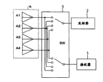
In radar installations of the present invention, each in described a plurality of antennas all has emission port and receiving port, and transmitter is connected with each emission port, and receiver is connected with each receiving port; Herein, each emission port is connected with common emitter selectively, and each receiving port also is connected with public receiver.
In described a plurality of antenna each all has the two-way switch that is used for switching between transmitting and receiving, and this two-way switch is when being placed in transmitting site, with in the described antenna relevant one be connected with described transmitter, and when it is placed in receiving position, with in the described antenna relevant one be connected with described receiver.
A kind of transceiver is provided for each in described a plurality of antenna, receiving port at the output port of transmitter described in this transceiver and described receiver is shared by transmitting and receiving, wherein, described transceiver is that described a plurality of antenna is common, and its with described antenna in selected one be connected to launch or to receive; At this, the number of the transceiver that is provided is less than the number of described a plurality of antennas, and described transceiver is connected to carry out described emission or reception with the antenna of choosing by the time-division switch.
Radar installations of the present invention further comprises voltage controlled oscillator, and being used for provides reference signal to described transmitter and described receiver, and wherein, this voltage controlled oscillator is shared by the described transmitter and the described receiver of described a plurality of antenna duplexers.
In radar installations of the present invention, described a plurality of antenna comprises with equi-spaced apart not along four antennas of line spread, and described signal processing unit is configured and makes it possible to the received signal that receives at described each antenna based on according to described received signal channel transfer sequence, form a plurality of digital beams of 11 channels, perhaps described signal processing unit is configured and makes it possible to form a plurality of digital beams of a plurality of channels that are less than 11 channels based on according to the part of described received signal channel transfer sequence in the received signal that described each antenna receives.
As mentioned above, radar installations of the present invention is configured at least one antenna emitting radio wave of choosing from a plurality of antennas with line spread at grade, and receives the reflection wave of the radiowave of this emission at described each antenna; Therefore, not only can utilize the antenna that lacks than the common radar device to obtain more channel, can also reduce the size and the cost of described radar installations.In addition, not only be used for emission but also when being used for receiving, channel quantity can increase greatly, and by the described received signal of combination, described directivity also is enhanced, thereby has improved the performance of described radar installations all when described a plurality of antennas.
In addition, in radar installations of the present invention, owing to compare with the structure of radar installations in the prior art, reduced number of antennas, and owing to described a plurality of antennas are arranged with the interval of policy selection, thereby can form multi channel digital beam, reduce described device size and cost simultaneously.
In radar installations of the present invention, because by realizing the formation of described multi-channel digital wave beam with the antenna of minimal amount with the described a plurality of antennas of being spaced of policy selection, can select the rough segmentation channel transfer sequence that uses the sub-divided channel transfer sequence of all channels or only use odd-numbered channels according to the environment for use of described radar installations; In using usually, often select rough segmentation channel transfer sequence, to improve the processing speed of orientation detection.
In addition, in radar installations of the present invention, because by realize the formation of described multi-channel digital wave beam with the antenna of minimal amount with the described a plurality of antennas of being spaced of policy selection, all channels can be divided into left half group and right half group, so that left side channel transfer sequence and the right channel transfer sequence to be provided, handle thereby can carry out twice orientation detection to same object; This helps improving the degree of accuracy of orientation detection.
Above-mentioned radar installations structure makes that the making of this radar installations is simpler, and reduced cost, for example, when described radar installations is installed in vehicle etc. and goes up as the anticollision radar installations, the global shape of described radar installations can be made into and be applicable to and be installed on this vehicle, and described orientation detection is handled can be faster, more efficient, and this becomes its advantage in anticollision is used.
Description of drawings
With reference to the accompanying drawings preferred embodiment is described, other characteristics of the present invention, target and advantage will become more obvious, in the accompanying drawings, run through the identical reference marks of several diagrammatic sketch, indicate identical or corresponding parts, and wherein:
Fig. 1 is a schematic block diagram, shows the structure according to radar installations of the present invention;
Fig. 2 is a diagrammatic sketch, and it is used for explaining the principle of operation according to radar installations antenna of the present invention;
Fig. 3 is a diagrammatic sketch, and it is used for explaining the reception work according to radar installations antenna of the present invention;
Fig. 4 is a sequential chart, and it is used for explaining first instantiation according to the antenna blocked operation of radar installations of the present invention;
Fig. 5 is a diagrammatic sketch, and it is used for explaining the formation of the first instantiation receive channel of described antenna blocked operation;
Fig. 6 is a sequential chart, and it is used for explaining second instantiation according to the antenna blocked operation of radar installations of the present invention;
Fig. 7 is a diagrammatic sketch, and it is used for explaining the formation of the second instantiation receive channel of described antenna blocked operation;
Fig. 8 is a sequential chart, and it is used for explaining first embodiment according to the antenna blocked operation of radar installations of the present invention;
Fig. 9 is a diagrammatic sketch, and it is used for explaining the formation of the first embodiment receive channel of described antenna blocked operation;
Figure 10 is a sequential chart, and it is used for explaining second embodiment according to the antenna blocked operation of radar installations of the present invention;
Figure 11 is a diagrammatic sketch, and it is used for explaining the formation of the second embodiment receive channel of described antenna blocked operation;
Figure 12 is a diagrammatic sketch, and it is used for explaining the first improvement example according to the antenna emission/reception structure of radar installations of the present invention;
Figure 13 is a diagrammatic sketch, its be used for explaining thunder according to the present invention state device antenna emission/reception structure second improve example;
Figure 14 is a diagrammatic sketch, and it is used for explaining first instantiation according to the antenna switch unit of radar installations of the present invention;
Figure 15 is a diagrammatic sketch, and it is used for explaining second instantiation according to the antenna switch unit of radar installations of the present invention;
Figure 16 is a diagrammatic sketch, and it is used for explaining the 3rd instantiation according to the antenna switch unit of radar installations of the present invention;
Figure 17 is a diagrammatic sketch, and it is used for explaining the 4th instantiation according to the antenna switch unit of radar installations of the present invention;
Figure 18 is a diagrammatic sketch, and it is used for explaining the 5th instantiation according to the antenna switch unit of radar installations of the present invention;
Figure 19 is a schematic block diagram, shows the structure according to a kind of radar installations of the previous technology that proposes; And
Figure 20 is a diagrammatic sketch, and it is used for explaining the formation that receives the receive channel of operation according to the antenna of radar installations shown in Figure 19.
Embodiment
The effect that can realize for a better understanding of the present invention at first will be discussed in more detail below the structure of the radar installations of the previous proposition that constitutes basis of the present invention.An example of the radar installations that is proposed is described below with reference to Figure 19 and 20.
Figure 19 is a schematic block diagram, shows the structure of described radar installations.In this radar installations, three emitting antenna A1, A2 is connected with switch unit 5 with A5 with A3 and receiving antenna A4.Transmitter 2, it comprises can export for example oscillator 3 of the high-frequency signal of 76GHz frequency band such as voltage controlled oscillator (VCO), and the receiver 4 that is connected with switch unit 5.The oscillator signal that is synchronized with oscillator 3 outputs, receiver 4 will send to signal processing control unit 1 from the signal that described receiving antenna receives.Signal processing control unit 1 is carried out the signal Processing that digital beam forms (DBF) based on the signal of this reception, and carries out the switching controls of described emitting antenna and receiving antenna via switch unit 5.
On the other hand, two receiving antenna A4 and A5 are provided at described receiving end.Switch SW2 at receiving end is connected with A5 with receiving antenna A4.To be that hilted broadsword is two put (SPDT) switch to this switch SW2, and its output is connected with A5 with receiving antenna A4.The single output of switch SW2 is connected with frequency mixer in the receiver 4.By according to the instruction manipulation switch SW2 from signal processing control unit 1 output, the received signal that is obtained by two receiving antenna A4 and A5 is optionally offered receiver 4.
How Figure 20 shows and switches between the antenna in radar installations shown in Figure 19.In this radar installations, if the time interval between receiving antenna A4 and the A5 is L, emitting antenna A1 then, A2 and A3 are with the spacing arrangement of 2L.
From emitting antenna A1, the radiowave that A2 and A3 launch is reflected by target object, and is received antenna A4 and A5 reception.Therefore, when described emitting antenna during in spatial movement, if correspondingly translation in the opposite direction of receiving antenna can be obtained same received signal.Therefore, when radiowave when emitting antenna A2 launches, signal that receives at receiving antenna A4 and A5 and the position that moves on to emitting antenna A1 as emitting antenna A2 and receiving antenna A4 and A5 round about translation equate with interval L between receiving antenna A4 and the A5 apart from the time signal that received the same.Similarly, when radiowave when emitting antenna A3 launches, signal that receives at receiving antenna A4 and A5 and the position that moves on to emitting antenna A1 as emitting antenna A3 and receiving antenna A4 and A5 translation 2L apart from the time signal that received the same.
Figure 20 shows in described pair relationhip and the relation of the position on described antenna alignment direction that transmits and receives between the antenna of each time instant.As can be seen, by suitably operating switch SW1 and SW2, can utilize five antennas altogether of forming by described three emitting antennas and described two receiving antennas to obtain six channel rays.This is equivalent to provide six receiving antennas for an emitting antenna.
Formerly in the another kind of radar installations of Ti Chuing,, then need to use to comprise two switch and the secondary switch structures that hilted broadsword three is put switch of putting of two hilted broadswords if provide six receiving antennas to be connected with a receiver; Contrast it seems, in the radar installations shown in Figure 19, though switch SW1 must be provided in described transmitting terminal, only needs to provide single-stage switch SW2 to be used for switching between receiving antenna A4 and A5.
In addition, in radar installations shown in Figure 19, if, can provide other receiving antenna A6 (not shown), and make the L that is spaced apart of itself and other antenna with antenna performance identical with A5 with receiving antenna A4 for the directivity that increases the wave beam obtained needs the increase channel quantity.In this case, each emitting antenna A1, the interval between A2 and the A3 will increase to 3L.According to the radar installations with this antenna structure, channel shown in Figure 20 has increased by three channels, and utilizes altogether six antennas can obtain the wave beam of nine channels.
It is said that above-mentioned radar installations structure can reduce cost so that the manufacturing of this radar installations is simpler, and, in such as application such as car radars, can make the global shape of this radar be suitable for being installed on the vehicle.Yet in the time of above this radar installations is installed in such as automobile etc., its position that can install is limited, and available installing space is also very limited; Therefore, the radar installations that uses in this type of is used must be as much as possible little.Yet, promptly allowing to reduce number of antennas, above-mentioned radar installations still has the improved place of a lot of needs aspect size reduction; And, from the angle of car steering security, also need further to provide the performance of this radar installations identification vehicle front target, and, also need to reduce the cost of this device.
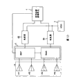
The embodiment of the radar installations that can realize the aforementioned purpose of the present invention is described below with reference to accompanying drawings.Fig. 1 shows structure according to radar installations of the present invention with simple form.The radar installations that herein illustrates is basic identical with the previous radar installations shown in Figure 19 that proposes, and the scanning of reflection wave that wherein is used to receive the radiowave of described emission is still undertaken by the signal Processing that digital beam forms (DBF).In radar installations shown in Figure 1, those parts identical with the parts of radar installations shown in Figure 19 are indicated with same reference number.The same with the radar installations of prior art, in this figure, the RF circuit module in the dotted line is from Monolithic Microwave Integrated Circuit (MMIC) structure, and it comprises transmitter 2, voltage controlled oscillator (VCO) 3, receiver 4, and switch unit 5.
In radar installations shown in Figure 1, four antenna A1, A2, A3 and A4 form aerial array A, and are connected with switch unit 5.Transmitter 2, can export for example oscillator 3 of the high-frequency signal of 76GHz frequency band such as voltage controlled oscillator (VCO), and receiver 4 all is connected with switch unit 5, wherein receiver 4 receives reflected signal, and this reflected signal is represented from the reflection of the emitted radio signal of described transmitter output.Receiver 4 is synchronized with from the oscillator signal of oscillator 3 outputs, and will send to the signal Processing that signal processing control unit 1. signal processing control unit 1 are carried out digital beam formation (DBF) based on the received signal that provides from receiver 4, and A1 is carried out switching controls to these four antennas of A4 via the switch SW in the switch unit 5 from the signal that described receiving antenna receives.
The key distinction of the basic radar installations of Fig. 1 and the radar installations of prior art is, in the radar installations of prior art, emitting antenna in comprising the aerial array of a plurality of antennas and receiving antenna only are used for emission respectively or receive, and in radar installations shown in Figure 1, the a plurality of antennas that form aerial array A are not exclusively used in emission or receive, but one or more in this a plurality of antennas or all not only can be used for emission but also can be used for reception.Utilize switch SW, described a plurality of antennas can be suitably switch between the reception of the reflection wave of emission that transmits that transmitter 2 provides and described emitted radio signal.The described radiowave that transmits is launched from the antenna of sequentially choosing, and the reflection wave of radiowave that should emission receives by described a plurality of antennas, thereby has realized the scanning that multichannel receives.
In addition, radar installations shown in Figure 1 is characterised in that described a plurality of antennas are arranged with unequal-interval, and is unlike in the radar installations of prior art with equidistant arrangement.If described a plurality of antenna is with equidistant arrangement, each receiving antenna can receive from the position of the reflection wave of the radiowave of an antenna emission of choosing and can only move with the distance that equates with described antenna distance.This will weaken and sequentially switch the advantage that described emitting antenna brings, and will make that increasing channel number becomes more difficult.Consider this point, set wideer antenna distance and narrower antenna distance, the twice that this wideer spacing is this narrower spacing is wide.Utilize this antenna alignment, can obtain more channel by less antenna.
Described wideer antenna distance is not limited to the twice of described narrower spacing, but importantly, the receiving position that each receiving antenna receives described reflection wave has moved the distance that equates with described antenna distance; After moving a plurality of antennas, obtain more channel with regard to available less antenna.For example, described wideer spacing can be set to 1.5 times of described narrower spacing.Below describing the situation that will be set to the twice of described narrower spacing with described wideer antenna distance is that example provides.
Preferably, a plurality of antennas that use in the radar installations shown in Figure 1 have identical antenna performance, and these antenna characteristic is directivity and gain for example.In addition, should have can be to the directivity of whole surveyed area emitting radio wave for each antenna.More preferably, described antenna is arranged so that their face that transmits and receives is point-blank arranged with single file.If the antenna performance between described antenna is different, the calculated amount that detects the phase place that comprises in the described received signal will increase, and this will influence the performance of described radar installations.
Radar installations shown in Figure 1 is the example that has been equipped with the device of four antennas.The key concept that digital beam in this radar installations forms (DBF) is described with reference to Fig. 2 and Fig. 3.DBF carries out in signal processing control unit 1; Herein, each received signal that comes from the aerial array A that comprises described a plurality of antennas is converted to digital signal by A/D, and the adjustment of beam scanning and sidelobe performance etc. is realized by digital signal processing.
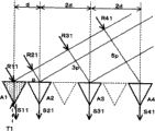
Fig. 2 shows four antenna A1 in the described radar installations, A2, and how A3 horizontally becomes delegation with A4.In this figure, each antenna is represented with triangle, and has been arranged four antennas.If the spacing between antenna A1 and the A2 represents that with d then the spacing between antenna A2 and A3 and antenna A3 and the A4 all is made as 2d, be the twice of the spacing d between antenna A1 and the A2.For making the easier identification of this spacing, used broken line triangle, one between antenna A2 and A3, another between antenna A3 and A4, to show the distance of each antenna to equate with an antenna, that is, 2d, spaced-apart.
At first, the assumed wireless electric wave chooses antenna A1 to emit as the T1 that transmits from first, as shown in Figure 2.Shade triangle among the figure is represented the emitting antenna of the described radiowave of selected emission.The radiowave of launching from emitting antenna A1 is reflected by target object, and its reflection wave returns aerial array A.Become radiowave that the direction at θ angle injects by comprising four antenna A1 that arrange as shown in the figure from center position about described radar, A2, the aerial array of A3 and A4 receives.As shown in the figure, with reflection wave R11 arrive antenna A1 place before the diffusion path length of process compare, arrive the reflection wave R41 of the reflection wave R21 of antenna A2, the reflection wave R31 that arrives antenna A3, arrival antenna A4, the path of process is wanted p far away, 3p and 5p (wherein p=dsin θ) respectively.
This means, arrive antenna A2, it is a certain amount of that the reflection wave R21 of A3 and A4, R31 and R41 and the reflection wave R11 of arrival antenna A1 have compared each self-dalay.Described retardation is respectively (2 π dsin θ)/λ, (6 π dsin θ)/λ and (10 π dsin θ)/λ, and wherein λ is the wavelength of described reflection wave.
As reflection wave R11, R21, R31 and R41 be by antenna A1 separately, A2, and when A3 and A4 receive, consequent received signal S11, S21, S31 and S41 offer receiver 4 via switch SW.Because the time of arrival of reflection wave is different with antenna, the phase place of relative received signal S11, received signal S21, each self-dalay of the phase place of S31 and S41 (2 π dsin θ)/λ, (6 π dsin θ)/λ and (10 π dsin θ)/λ.
If the phase place of described each received signal has shifted to an earlier date the amount that equates with the retardation of described received signal by the digital processing of carrying out in signal processing control unit 1, then can obtain in phase to be received identical effect by all antennas, and the directivity of all described antennas all is arranged in the θ direction with reflection wave from the θ direction.
Then, as shown in Figure 3, when emitting antenna switches to antenna A2 from antenna A1, radiowave is launched from antenna A2 as the T2 that transmits.The described radiowave of launching from emitting antenna A2 is reflected by target object, and its reflection wave returns aerial array A.As shown in Figure 2, the reflection wave that arrives from the direction that becomes the θ angle with the center position of described radar is comprised four antenna A1, A2, and the aerial array of A3 and A4 receives.
Antenna A1, A2, A3 and A4 receive reflection wave R12, R22, R32 and the R42 corresponding to the T2 that transmits separately.As reflection wave R12, R22, R32 and R42 be by antenna A1 separately, A2, and when A3 and A4 receive, consequent received signal S12, S22, S32 and S42 offer receiver 4 via switch SW.Herein, as shown in the figure, with reflection wave R12 before arriving antenna A1 the diffusion path length of process compare, arrive the reflection wave R22 of antenna A2, arrive the reflection wave R32 of antenna A3, and the reflection wave R42 that arrives antenna A4, the path of process is wanted p far away, 3p and 5p (wherein p=dsin θ) respectively.
Yet different with the situation of Fig. 2, under the situation of Fig. 3, because emitting antenna moves on to antenna A2 by antenna A1, be set as the reference time time of arrival that arrives the reflection wave of antenna A2.So, compare with the situation among Fig. 2, moved the amount that equates with amount of movement in the horizontal direction from antenna A1 to antenna A2 in the in-position of the reflection wave of each antenna.
Then, compare with the received signal S22 that obtains from the reflection wave R22 that receives at antenna A2, come from the phase place of received signal S12 of antenna A1 leading (2 π dsin θ)/λ, with respect to the phase place of the received signal S22 that receives at antenna A2 delay is arranged from the phase place of the reflection wave R32 that arrives at antenna A3 and A4 and resulting received signal S32 of R42 and S42 respectively simultaneously.Retardation herein is respectively (4 π dsin θ)/λ and (8 π dsin θ)/λ.
Therefore, in signal processing control unit 1 in the digital processing process of each antenna receiving signal, have received signal S12 that phase place shifts to an earlier date and carried out phase delay according to the lead of its phase place.On the other hand, received signal S32 and the S42 that all has phase delay carried out phase place in advance according to its phase-delay quantity separately; Like this, just can obtain in phase to be received identical result by all antennas, and the directivity of all described antennas all is arranged in the θ direction with the reflection wave that arrives.
When the FM-CW ripple when transmitting, by sequentially selecting antenna A1, A2, A3 and A4 as each comprised by the switch SW that controls aforementioned radar installations increase and reduce the FM-CW ripple triangular wave part during emitting antenna, launch described FM-CW ripple.During each, the described reflection wave that transmits is by antenna A1, A2, and A3 and A4 receive.Like this, launch described radiowave, and receive the reflection wave of the radiowave of described emission, can utilize the space suitable to realize 11 channels with six antennas by described four antennas by from described four transmit/receive antennas, selecting one.
How Fig. 4 and Fig. 5 show in the aerial array that uses described four antennas, utilize the space that is equivalent to six antennas to realize described 11 receive channels.Fig. 4 shows first instantiation of the antenna blocked operation in described radar installations.Be shown in the sequential chart to A4 and receiving antenna A1 to the triangular wave cycle of the time of switching between the A4 at emitting antenna A1 with the FM-CW ripple of being launched.In Fig. 4, the emitting antenna A1 that receiving antenna 1 indication is selected to launch the FM-CW ripple each in the A4, and after emission, it is switched to the receiving antenna that is used to receive described reflection wave.On the other hand, the receiving antenna 2 indication receiving antenna A1 that is switched to the receiving antenna that is different from receiving antenna 1 each in the A4.
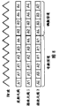
Fig. 5 shows how to form described receive channel, that is, carrying out according to switching sequence figure shown in Figure 4 in first instantiation of antenna blocked operation, transmits and receives relevant received signal channel transfer sequence with antenna.In Fig. 5, the transverse axis express time, triangle is represented receiving antenna, simultaneously the shade triangle is represented both to be used to launch and also is used to the antenna that receives.The receive channel of each antenna illustrates by the emitting antenna of reference triangle FM-CW ripple during each.In illustrated example, form by three triangular waves in the FM-CW ripple shown in Figure 4 during each.Therefore, first to comprising 12 triangular waves between the fourth phase altogether.
Spacing between spacing between antenna A2 and the A3 and antenna A2 and the A3 is made as the twice of spacing between antenna A1 and the A2 separately.Therefore, during first of described FM-CW ripple in, antenna A1 receives reflection waves at channel 6, antenna A2 is at channel 7, antenna A3 is at channel 9, and antenna A4 is at channel 11.
During second of described FM-CW ripple, because emitting antenna switches to antenna A2, and as reference, the position in the in-position of the received signal at each antenna place is relative between the first phase has been moved the distance that equates with spacing d significantly with the phase place of the received signal at antenna A2 place.Like this, during the second, the reflection wave on the antenna A1 receive channel 5, on the antenna A2 receive channel 6, on the antenna A3 receive channel 8, and on the antenna A4 receive channel 10.
In between the ensuing third phase, emitting antenna switches to antenna A3, and between the fourth phase, emitting antenna switches to antenna A4.Therefore, during these in, compare in the reflection wave in-position at each antenna place and to have moved the distance that equates with spacing 2d significantly during last.Therefore, during third and fourth in, be similar to during described first and second, reflection wave is received in the position of moving spacing 2d by each antenna.As a result, when with reference to the antenna of the described radiowave of emission, this means from switching in the circulation to one the fourth phase between the described first phase that the reflection wave of described transmitted wave is in that all channels of 11 obtain receiving from channel 1 to channel.
Herein, on the 6th channel, taken place to repeat to receive, but this repetition is inevitable, because in the situation of Fig. 5, this channel is set as with reference to channel.Receive as for repeating on the 4th and the 8th channel, on the other hand, any in the described received signal all not necessarily.Herein,, can limit and do not receive described redundant signals, perhaps receive this redundant signals but do not carry out to received signal signal Processing by controlling described switch SW if consider calculated load.
The antenna blocked operation of carrying out above-mentioned qualification illustrates as second instantiation in Fig. 6 and Fig. 7.With the same among Fig. 4, in Fig. 6, be shown in the sequential chart to the triangular wave cycle of the time of switching between the A4 with receiving antenna A1 to A4 with the FM-CW ripple of described emission at emitting antenna A1.In Fig. 6, the emitting antenna A1 that receiving antenna 1 expression is selected to launch described FM-CW ripple is to each of A4, and after launching, it is switched to the receiving antenna that is used to receive described reflection wave.On the other hand, the receiving antenna 2 expression receiving antenna A1 that is switched to the receiving antenna that is different from receiving antenna 1 is to each of A4.
Fig. 7 shows how to form described receive channel, that is, carrying out according to switching sequence figure shown in Figure 6 in second instantiation of antenna blocked operation, transmits and receives relevant received signal channel transfer sequence with antenna.In Fig. 7, with the same among Fig. 5, the transverse axis express time, triangle is represented receiving antenna, and the shade triangle is represented both to be used to launch and also is used to the antenna that receives.The receive channel of each antenna is by illustrating with reference to the emitting antenna of described triangle FM-CW ripple during each.
In second instantiation, transmit and receive relevant received signal channel transfer sequence with antenna and the difference in first example is, in the sequential chart of Fig. 6, antenna A3 is only selected in a triangular wave circulation of described FM-CW ripple to be emitting antenna, and in this circulation, only antenna A1 is switched as receiving antenna 2.On the other hand, shown in broken line triangle among Fig. 7, antenna A2 and antenna 4 are not chosen as receiving antenna 2 in all having between the third phase.
This is because antenna A3 has been chosen as the receiving antenna 2 of the 8th channel during the second, also because antenna A3 is selected for the 4th channel in being intended between the fourth phase.Like this, can avoid repetition on the same channel.Use this received signal channel transfer sequence, in the radar installations of A4, can utilize the space that equates with six antennas to realize 11 receive channels at four antenna A1 that assembled equi-spaced apart not as shown in Figure 1.From between the described first phase, switching the circulation, utilize ten triangular waves in the described FM-CW ripple can form a plurality of wave beams, thereby and improve conversion speed to one the described fourth phase.
In first and second instantiations, described received signal channel transfer sequence is made description, it in the radar installations of A4, can utilize the space that equates with six antennas to realize 11 channels at four antenna A1 that assembled equi-spaced apart not as shown in Figure 1; According to this received signal channel transfer sequence, always can in the operation of described radar installations, obtain 11 received signal channels, thereby reduced the size and the cost of this radar installations, strengthened the directivity when received signal combines, thereby improved the performance of this radar installations.
Such radar installations for example can be installed on the vehicle, to be used for detecting the orientation of the target object that is positioned at the place ahead.In such application, the situation of orientation detection performance that need be very high is arranged, the speed that orientation detection is also arranged is than the prior situation of performance.According to the radar installations shown in Fig. 1, can utilize the space that equates with six antennas to realize 11 channels, reduce size and cost, still, although can obtain 11 receive channels, desired in some cases orientation detection speed possibly can't obtain.
Under the circumstances, transmitting and receiving relevant received signal channel transfer sequence with antenna in the radar installations shown in Figure 1 is modified, so that described multi channel formation can be according to the environment of described radar running, between roughcast formula and thin pattern, switch, and make that described pattern can be from thin mode switch to the roughcast formula when requiring faster orientation detection speed.Fig. 8 and Fig. 9 show first embodiment of the antenna blocked operation in the radar installations of the present invention.
In Fig. 8,, illustrate with time series to the triangular wave cycle of the time of switching between the A4 with receiving antenna A1 to A4 with the FM-CW ripple of being launched at emitting antenna A1 with the same in Fig. 4.Equally, in Fig. 8, the emitting antenna A1 that receiving antenna 1 expression selects to be used for to launch described FM-CW ripple is to each of A4, and, it is switched to the receiving antenna that is used to receive described reflection wave emission back, and the receiving antenna A1 that receiving antenna 2 expressions are switched to the receiving antenna that is different from receiving antenna 1 each in the A4.
Fig. 9 shows how to form described receive channel, that is, carrying out according to switching sequence figure shown in Figure 8 among first embodiment of antenna blocked operation, transmits and receives relevant received signal channel transfer sequence with antenna.In Fig. 9, with the same among Fig. 5, the transverse axis express time, triangle is represented receiving antenna, and the shade triangle is represented both to be used to launch and also is used to the antenna that receives.The receive channel of each antenna illustrates by the emitting antenna of reference triangle FM-CW ripple during each.
Different with first and second instantiations of describing before, in the Fig. 8 and first embodiment shown in Figure 9, always do not form 11 received signal channels, but these 11 channels that will form are divided into one group of odd-numbered channels and one group of even-numbered channels.As shown in Figure 8, a plurality of adjacent triangular wave in the FM-CW ripple has 11 needed length of receive channel of formation, in described received signal channel transfer sequence, the first half is allocated for and forms described odd number receive channel, and then half is used to form described even number receive channel.
At first, will the formation of the odd number receive channel in described 11 channels be described.Comprise first three the triangular wave cycle in the FM-CW ripple shown in Figure 8 between the first phase shown in Figure 9, and second to a triangular wave cycle that respectively comprises between the fourth phase subsequently.Between the first phase, antenna A1 is chosen as emitting antenna, and three cycles of described triangular wave are from antenna A1 emission, and antenna A2, A3 and A4 are chosen as the receiving antenna in each emission cycle separately.Antenna A2 receives the signal on the 7th channel, and antenna A3 receives the signal on the 9th channel, and antenna A4 receives the signal on the 11st channel.
Subsequently, in the second phase, antenna A2 is chosen as emitting antenna, and antenna A1 is chosen as receiving antenna 2, and antenna A1 receives the signal on the 5th channel.Then, between the third phase, antenna A3 is chosen as emitting antenna, and antenna A1 is chosen as receiving antenna 2, and antenna A1 receives the signal on the 3rd channel.Further, between the fourth phase, antenna A4 is chosen as emitting antenna, and antenna A1 is chosen as receiving antenna 2, and antenna A1 receives the signal on first channel.In Fig. 9, all are not chosen as receiving antenna 2 and the antenna with dashed lines triangle that the formation of described odd number receive channel does not have a contribution are illustrated.
As mentioned above, in described 11 channels, form described six odd number receive channels with six triangular wave cycles of described FM-CW ripple.Subsequently, form even-numbered channels in described 11 receive channels with how describing with above-mentioned six triangular waves four triangular waves afterwards.As shown in Figure 8, form described even number receive channel with described back four triangular wave cycles in half, and in Fig. 9, the select time with dashed lines triangle of selected each antenna as receiving antenna 2 illustrates.
As can be seen from Figure 9, when forming described even number receive channel, do not have any contribution between the described first phase, and described second and the fourth phase between made contribution for the formation of described receive channel.The second phase comprises triangular wave two the triangular wave cycles afterwards that are used for forming described odd number receive channel, and comprises two triangular wave cycles after above-mentioned two triangular wave cycles between the described fourth phase, thereby described even number receive channel forms.
At first, in the second phase, antenna A2 is chosen as emitting antenna, and two triangular wave cycles are from antenna A2 emission, and antenna A3 and A4 are chosen as the receiving antenna 2 in each emission cycle separately.The signal that antenna A2 receives on the 6th channel as receiving antenna 1, the signal that antenna A3 receives on the 8th channel as receiving antenna 2, and antenna A4 receives the signal on the 10th channel.Then, between the fourth phase, antenna A4 is chosen as emitting antenna, and two triangular wave cycles are from antenna A4 emission, and antenna A2 and A3 are chosen as the receiving antenna 2 in each emission cycle separately.The signal that antenna A2 receives on the second channel as receiving antenna 2, the signal that antenna A3 receives on the 4th channel as receiving antenna 2.
As mentioned above, in described 11 channels, with five even number receive channels of four triangular wave cycles formation of described FM-CW ripple.Therefore, by after forming aforementioned odd number receive channel, forming five even-numbered channels immediately, just can form 11 received signal channels with ten triangular wave cycles.
The same with the Fig. 6 and second instantiation shown in Figure 7, described multi channel formation not only can improve performance, and can also realize the acceleration of signal Processing.Herein, the formation of aforementioned six odd number receive channels can follow closely after the formation of above-mentioned five even number receive channels; In this case, also can form 11 received signal channels with ten triangular wave cycles.
Be installed on the vehicles of automobile and so on for example at radar installations and be used for detecting the application in the orientation of the target object that is arranged in the place ahead, such as vehicle with low speed or under the situation of congested travels down, just need utilize all channels to carry out accurate orientation detection; On the other hand, under the situation of normal driving, need to increase the processing speed of orientation detection.For satisfying these needs, when the accurate orientation detection of needs, described received signal channel transfer sequence is switched to thin antenna transmit/receive formula, and after the received signal channel transfer sequence according to described odd-numbered channels forms described receive channel, and then the received signal channel transfer sequence according to described even-numbered channels forms described receive channel, thereby utilizes all 11 channels to form a plurality of wave beams; Like this, the directivity of described radar installations is improved, and can realize high resolving power.
On the other hand, do not needing to utilize all channels to carry out accurate orientation detection, but under the situation of the processing speed of needs raising orientation detection, described received signal channel transfer sequence is switched to the roughcast formula that is not high resolution model, promptly, switch to the transfer sequence that only forms described odd number receive channel, and only utilize six channels in described 11 channels to form multi-beam; Under normal driving situation, carry out this transfer sequence repeatedly, to improve the processing speed of orientation detection in the described radar installations.Like this, need not to change the structure of described radar installations, switch to appropriate mode and only will transmit and receive relevant received signal channel transfer sequence with antenna, the environment for use that described radar installations just can be set to install therewith is complementary.
Figure 10 and Figure 11 show second embodiment, wherein, transmit and receive relevant received signal channel transfer sequence with antenna in the radar installations shown in Figure 1 and are modified, to improve the degree of accuracy of orientation detection; In this embodiment, the many received signals channel that will form that is used for detecting the target object that is positioned at this radar installations the place ahead is divided into two groups, left side group and the right group, and form multi-beam with a left side half of a plurality of channels and right half of a plurality of channels respectively, can carry out twice so that orientation detection is handled.
In Figure 10,, be used for that the triangular wave cycle with the FM-CW ripple of being launched is shown in time series to A4 and receiving antenna A1 to the time of switching between the A4 at emitting antenna A1 with the same among Fig. 4.Equally, in Figure 10, the emitting antenna A1 that receiving antenna 1 expression is selected to launch described FM-CW ripple each in the A4, and, after the emission, it switches to the receiving antenna that is used to receive described reflection wave, and the receiving antenna A1 that receiving antenna 2 expression is switched to the receiving antenna that is different from receiving antenna 1 each in the A4.
Figure 11 shows how to form described receive channel, that is, carrying out according to switching sequence figure shown in Figure 10 among second embodiment of antenna blocked operation, transmits and receives relevant received signal channel transfer sequence with antenna.In Figure 11, with the same among Fig. 5, the transverse axis express time, triangle is represented receiving antenna, and the shade triangle is represented both to be used to launch and also is used to the antenna that receives.The receive channel of each antenna illustrates by the emitting antenna with reference to described triangle FM-CW ripple each several part.In example shown in Figure 11, left half channel group is made up of the 6th to the 11st channel, and right half channel group is made up of first to the 6th channel.
Different with first and second instantiations of describing before, in the Figure 10 and second embodiment shown in Figure 11, always do not form described 11 received signal channels, but these 11 channels that will form are divided into each half group on left side being made up of a plurality of channels and right half group.As shown in figure 10, a plurality of adjacent triangular wave in the described FM-CW ripple has described 11 needed length of receive channel of formation, the first half is allocated for the receive channel that forms half group on a described left side in the described received signal channel transfer sequence, and then half is used to form the receive channel on half group on the described right side.Herein, be set to be contained in the right half receive channel group of left half-sum simultaneously with reference to the 6th channel of received signal channel.In addition, for utilizing a plurality of channels in the described right side of described left half-sum half, raising carries out the resolution of orientation detection, each that can be in the right half receive channel group of described left half-sum adds one or more extra channels, so that each group comprises seven or more channel.
At first, will the formation of the receive channel in the left side half of described 11 channels be described.During the shown in Figure 9 the first to the 6th each comprises a triangular wave cycle in the FM-CW ripple shown in Figure 10, and respectively comprise two triangular wave cycles of FM-CW ripple shown in Figure 10 during the 7th and the 8th, that is, be used to form described 11 channels during having eight.Between the first phase, antenna A1 is chosen as emitting antenna, and the one-period of triangular wave is from antenna A1 emission, and antenna A1 is chosen as receiving antenna 1 simultaneously, and antenna A4 is a receiving antenna 2.Antenna A1 and A4 receive the signal on the 6th and the 11st channel respectively.
Subsequently, in the second phase, antenna A2 is chosen as emitting antenna, and antenna A2 is a receiving antenna 1 simultaneously, and antenna A4 is a receiving antenna 2, and the two receives the signal on the 6th and the 10th channel respectively.In ensuing the 3rd to the 6th part, antenna A1 and A2 are alternately elected as emitting antenna, and antenna A1 and A2 are alternately elected as receiving antenna 1 simultaneously, and are chosen as receiving antenna 2 corresponding to the antenna A2 or the A3 of one of the 9th to the 7th channel.Utilize this transfer sequence, described reference channel signal obtains receiving, and the signal on the 9th to the 7th channel is sequentially received.
In a left side half received signal channel transfer sequence that carries out according to above-mentioned antenna option program, utilize six received signal channels forming by the 6th to the 11st channel can form multi-beam.Described signal processing unit carries out the orientation detection processing based on the described multi-beam of six channels formation of left-half of utilizing.
Below, will the formation of the receive channel in the right half part be described.During the 6th, antenna A2 is chosen as emitting antenna, and the one-period of triangular wave is from antenna A2 emission, and antenna A2 is chosen as receiving antenna 1 simultaneously, and antenna A1 is a receiving antenna 2.Antenna A2 and A1 receive the signal on the 6th and the 5th channel respectively.
During the 7th, antenna A3 is chosen as emitting antenna, and two cycles of triangular wave, antenna A3 was chosen as receiving antenna 1 simultaneously sequentially from antenna A3 emission, and antenna A2 and A1 are sequentially elected as receiving antenna 2.Antenna A2 and A1 receive the signal on the 4th and the 3rd channel respectively.
Subsequently, during the 8th, antenna A4 is chosen as emitting antenna, and two cycles of triangular wave are sequentially launched from antenna A3, simultaneously antenna A4 is chosen as receiving antenna 1, and antenna A2 and A1 sequentially elected as receiving antenna 2, and receives the signal on second and first channel respectively.In Figure 11, be not chosen as receiving antenna 2 and the antenna with dashed lines triangle that the formation of described receive channel does not have a contribution is illustrated.
In the right side half received signal channel transfer sequence that carries out according to above-mentioned antenna option program, utilize six received signal channels forming by first to the 6th channel can form multi-beam.Described signal processing unit carries out orientation detection based on the multi-beam of utilizing six channels of left-half to form to be handled.
As mentioned above, in described 11 channels, utilize five triangular wave cycles of described FM-CW ripple to form half group on a described left side and each right half group six receive channel.Therefore, described signal processing unit can carry out left half group and right half group orientation detection processing respectively based on the signal that receives in six channels of each group.
Carry out orientation detection one time by above-mentioned per five triangular wave cycles at described FM-CW ripple, can improve the processing speed of orientation detection, this is the same with the receive channel of odd-numbered channels situation about forming among first embodiment.In addition, handle, this means to repeat the orientation detection under equal resolution twice, thereby can improve the degree of accuracy of described orientation detection owing to can utilize following five triangular wave cycles of described FM-CW ripple to carry out orientation detection once more.
State in the device at thunder shown in Figure 1, end from described aerial array, four antennas are sequentially switched to as emitting antenna work by switch unit 5, if but from being positioned at the antenna at described aerial array middle part, rather than begin sequentially to choose antenna from an end of this aerial array, can form described 11 channels to begin sequentially to choose the same mode of antenna with a end from this array.
In the example of having described, all four antennas are all sequentially elected as emitting antenna and are obtained described 11 channels, but have the situation that does not need so high beam directional.For example, consider that described radar installations is installed in the situation on the vehicle; At this moment,, make the arithmetic speed of this radar installations can not catch up with the speed of a motor vehicle if the speed of a motor vehicle is very fast, and if very near apart from the distance of target object, just may need to reduce operand and improve arithmetic speed.
For handling this class situation, can be by for example in described radar installations, sequentially selecting antenna A1 and A2 as emitting antenna, rather than sequentially select all four antennas as emitting antenna, only obtain five channels, perhaps, by sequentially selecting antenna A1, A2 and A3 to obtain nine channels as emitting antenna.Like this, select as emitting antenna by selecting one group of suitable antenna, then need not to change the structure of described four antennas, and only need just can change the quantity of the channel that will form by the blocked operation of controlling described switch SW.
Above-mentioned radar installations embodiment has handled this device and has had the situation of four emission/reception community antennas, but in order to obtain the channel of suitable quantity, do not need four all antennas all not only to be used for emission but also be used for receiving, be used for receiving yet and only need in these four antennas two or three both to be used for emission.On the other hand, if wish to increase significantly the quantity of channel, can increase antenna A5 (not shown) in the position that is separated by with the 2d spacing.
In addition, in each embodiment of above-mentioned radar installations, described device has four emission/reception community antennas, and utilizes the space that equates with six antennas to form the digital beam of 11 channels.,, just can realize target of the present invention herein, that is, only utilize less antenna number just can form digital beam with more number of channel if antenna number is kept to three.When antenna number was three, maximum numbers of channel that can access were seven.At this moment, though described resolution descends, described device size can be less than the DBF radar with nine channels of prior art.
On the other hand, if antenna number increases to five or more, then resolution improves, but correspondingly, reduces size and cost and also become difficult.Therefore, when antenna number was four, 11 channels that can utilize multipotency to generate formed digital beam, this not only may realize the higher resolution of resolution than the antenna in the DBF radar of prior art, and, when reducing this installation cost, can also reduce its size.
Therefore, we can say that the structure of described four antennas is the optimal selections that form the multi-channel digital wave beam.Like this, when four antennas are provided,, can reduce the quantity of the channel that will generate, only form digital beam with the channel that is less than 11 for the speed ratio of handling such as orientation detection detects the prior situation of degree of accuracy.For example, the number of channel can be reduced to nine, resolution is reduced to the degree that can compare with the DBF radar installations of prior art.Therefore, four antennas in the radar installations of the present invention have kept the compatibility of the antenna in the DBF radar installations with prior art.
As mentioned above, in the structure of radar installations shown in Figure 1, a plurality of antennas same plane with line spread on, described radiowave is launched from least one antenna of choosing, and the reflection wave of the radiowave of being launched is received by each antenna; Therefore, not only can utilize than normal radar device antenna still less and obtain more channel, and, the size and the cost of this radar installations can be reduced.Specifically, when described a plurality of antennas not only had been used for emission all but also had been used to receive, the number of channel can significantly increase, and when described received signal in conjunction with the time, also increased described directivity, thereby improved the performance of described radar installations.
The improvement example of the foregoing description is described with reference to Figure 12 to 18 below; Improvement example shown below is based on the structure of radar installations of the present invention shown in Figure 1, and relates to the received signal channel transfer sequence according to first and second embodiment, is used to raise the efficiency, and reduces cost, perhaps further structure reduced in size.
In the first improvement example shown in Figure 12, switch unit 5 is omitted, transceiver 61,62, and 63 and 64 separately not only as transmitter 2 but also as receiver 4, respectively with four antenna A1, A2, A3 is connected with A4.This structure is very effective in some that would rather increase that cost also will prevent signal attenuation are used.Can be provided for generating the described voltage controlled oscillator that transmits (VCO) for each transceiver, but in the example that illustrates, the shared voltage controlled oscillator 3 of all transceivers is so that it is shared in the identical transmiting signal source between them, and help to receive the synchronous of operation, reduce cost simultaneously.Can utilize such as hybrid circuit or distributor circuit and be configured for diplexer that each antenna is switched between transmitting and receiving; In addition, amplifier (AMP) and attenuator (ATT) can embed the described end that transmits and receives, thereby can by ride gain or the damping capacity opening and closing are described transmit and receive.Like this, each antenna all can switch between transmitting and receiving with time division way.
The second improvement example shown in Figure 13 has been used the structure between structure shown in Figure 1 and structure shown in Figure 12, and its purpose is, described signal attenuation is reduced to low relatively level, can also reduce simultaneously because of increasing the cost increase that transceiver causes.For this reason, switch unit 5 is different with omitting in the example shown in Figure 12, and the structure of Figure 13 has used that hilted broadsword is two puts (SPDT) switch, and wherein each is used for two switchings between the antenna, and switch SW1 and SW2 are switched between described four antennas by signal processing control unit 1 control.In this case, it is shared that voltage controlled oscillator also offers transceiver 65 and 66.
Improvement example about the embodiment of transmitter and receiver dependency structure has more than been described; The instantiation of switch unit 5 in the radar installations of Fig. 1 below will be described.The diagrammatic sketch that below provides concentrates on the structure of switch unit 5, therefore, and signal processing control unit 1 that not shown described radar installations is basic and voltage controlled oscillator 3.Four antenna A1, A2, A3 and A4 form described aerial array A, and transmitter 2 is connected with switch unit 5 with receiver 4, and the blocked operation of switch SW is by signal processing control unit 1 control, so that described four antennas switch between transmitting and receiving with time division way.
In first instantiation shown in Figure 14, be four antenna A1, A2, each of A3 and A4 provides emission port and receiving port, makes described antenna to be connected with transmitter 2 or receiver 4 with time division way.
In second instantiation shown in Figure 15, opposite with described first instantiation, provide at transmitter 2 and receiver 4 ends to transmit and receive port.In this example, described antenna also can be connected with transmitter 2 or receiver 4 with time division way.
In the 3rd instantiation shown in Figure 16, be four antenna A1, A2, each among A3 and the A4 all provides a port, makes to select each antenna by the operation of transmitter 2 or receiver 4 ends.In this example, described antenna also can be connected with transmitter 2 or receiver 4 with time division way.
Simultaneously, in described the 3rd instantiation, transmitter 2 can be controlled being connected of each antenna independently with receiver 4, and in the 4th instantiation shown in Figure 17, Duplexer Unit is provided among the switch unit 5, so that described antenna can be connected with transmitter 2 or receiver 4 with time division way.Described Duplexer Unit can be constructed to realize cheap circuit structure from hybrid circuit or distributor circuit.
In the 5th instantiation shown in Figure 180, the Duplexer Unit in described the 4th instantiation is constructed with the two switchs of putting of hilted broadsword; In this example, described antenna also can be connected with transmitter 2 or receiver 4 with time division way.
In described first to the 5th instantiation,, can reduce the size of switch unit 5 herein, if the switch SW in the switch unit 5 is made of the two-way switch that not only can be used for launching but also can be used for receiving.
Claims (22)
1. radar installations, comprise a plurality of antennas, have identical antenna performance and arrange with single file with not equidistant interval, transmitter, be used for from least one antenna emitting radio wave of selecting at described a plurality of antennas, receiver, be used for receiving the received signal of expression reflection wave of the radiowave of described emission at each antenna, and signal processing unit, be used to utilize a plurality of received signal channels that draw from described received signal to carry out digital beam formation, described radar installations further comprises:
First selects switch, be used for by during a plurality of continuously each will link to each other with described transmitter as the selected antenna of emitting antenna fetch described continuous a plurality of during in sequentially provide the radio wave transmission signal to described antenna; And
Second selects switch, be used for fetching in described continuous each during a plurality of and sequentially provide described received signal to described receiver by sequentially linking to each other with described receiver as the selected antenna of receiving antenna in described each during continuously a plurality of, and, wherein:
About the described emitting antenna during identical, for described each during continuously a plurality of, each of described receiving antenna is distributed to one of described received signal channel, and wherein said received signal channel is by from 1 to N numbering and its number number greater than antenna, wherein
Described signal processing unit utilizes the first received signal channel group and the second received signal channel group to carry out digital beam respectively and forms.
2. according to the radar installations of claim 1, wherein, the described first received signal channel group comprises odd number received signal channel, and the described second received signal channel group comprises even number received signal channel.
3. according to the radar installations of claim 1, wherein, the described first received signal channel group comprises the first half of a described N channel, and the described second received signal channel group comprises the latter half of a described N channel.
4. according to the radar installations of claim 1, wherein, all described a plurality of antennas all not only can be used for emission but also can be used for receiving.
5. according to the radar installations of claim 1, emitting antenna is selected as one of described receiving antenna described in wherein said each during a plurality of continuously, as the reference antenna of same period.
6. according to the radar installations of claim 5, the phase place of the received signal that receives by described receiving antenna during wherein said signal processing unit (1) is adjusted in each based on the phase place of the received signal that is received by described reference antenna during identical, and (2) received signal of being conditioned based on described phase place is carried out digital beam and is formed.
7. according to the radar installations of claim 6, wherein, described signal processing unit is the described first received signal channel group and carries out orientation detection for the described second received signal channel group and handle.
8. according to the radar installations of claim 1, wherein, the arrangement of described a plurality of antennas makes that antenna spacing and another ratio to the antenna spacing between the adjacent antenna between the predetermined a pair of adjacent antenna is 1: 2.
9. radar installations according to Claim 8, wherein, described a plurality of antennas comprise first to the 4th antenna of arranging along linear sequence,
Described first and second antennas are spaced with first, and while described second and third antenna and described third and fourth antenna are spaced with second separately, and wherein,
Described second doubles described first at interval at interval.
10. according to the radar installations of claim 1, wherein, each in described a plurality of antennas all has emission port and receiving port, and
Transmitter selects switch to be connected with each emission port via described first, and receiver selects switch to be connected with each receiving port via described second.
11. radar installations according to claim 1, wherein, each of described a plurality of antennas provides emission port and receiving port, each emission port selects switch to be connected with common emitter selectively via described first, and each receiving port selects switch to be connected with public receiver via described second.
12. radar installations according to claim 1, wherein, a kind of transceiver is provided for each in described a plurality of antenna, receiving port at the output port of transmitter described in this transceiver and described receiver is shared by transmitting and receiving, and each of described output port is connected to described first and selects switch, and each of described receiving port is connected to described second and selects switch.
13. according to the radar installations of claim 12, wherein, described transceiver is that described a plurality of antenna is common, and it selects switch or described second to select one in switch and the described antenna to be connected to launch or to receive via described first.
14. according to the radar installations of claim 13, wherein, each of described transceiver is that the port of described a plurality of antennas is common, the number of the described transceiver that provides is less than the number of described a plurality of antennas.
15. according to the radar installations of claim 13, wherein, described transceiver is switched with time division way and is used for emission or reception.
16., further comprise voltage controlled oscillator according to the radar installations of claim 1, be used for providing reference signal to described transmitter and described receiver, wherein,
Described voltage controlled oscillator is shared by the described transmitter and the described receiver of described a plurality of antenna duplexers.
17. according to the radar installations of claim 1, wherein, the described first received signal channel group comprises that all described N channels and the described second received signal channel group comprise described odd number received signal channel or described even number received signal channel, and
Described signal processing unit utilizes any described received signal channel group to carry out orientation detection according to environment.
18. according to the radar installations of claim 1, wherein, the described first received signal channel group comprises that all described N channels and the described second received signal channel group comprise the first half of a described N channel or the latter half of a described N channel, and
Described signal processing unit utilizes any described received signal channel group to carry out orientation detection according to environment.
19. according to the radar installations of claim 14, wherein, during each is described in, described transceiver is switched with time division way and is used for emission or receives.
20. according to the radar installations of claim 9, wherein, described continuously a plurality of during in, described signal processing unit forms a plurality of digital beams of 11 channels based on the received signal that receives at first to the 4th antenna.
21. according to the radar installations of claim 1, wherein, described a plurality of antennas comprise with equi-spaced apart not along four antennas of line spread, and
Described continuously a plurality of during in, described signal processing unit forms a plurality of digital beams of 11 channels based on the received signal that receives at described each antenna.
22. according to the radar installations of claim 1, wherein, described a plurality of antennas comprise with equi-spaced apart not along four antennas of line spread, and
Described continuously a plurality of during in, described signal processing unit forms a plurality of digital beams of a plurality of channels that are less than 11 channels based on the part in the received signal that receives at described each antenna.
Applications Claiming Priority (2)
| Application Number | Priority Date | Filing Date | Title |
|---|---|---|---|
| JP2004182537A JP2006003303A (en) | 2004-06-21 | 2004-06-21 | Radar device |
| JP182537/2004 | 2004-06-21 |
Publications (2)
| Publication Number | Publication Date |
|---|---|
| CN1712986A CN1712986A (en) | 2005-12-28 |
| CN100451675C true CN100451675C (en) | 2009-01-14 |
Family
ID=34978877
Family Applications (1)
| Application Number | Title | Priority Date | Filing Date |
|---|---|---|---|
| CNB2005100719909A Expired - Fee Related CN100451675C (en) | 2004-06-21 | 2005-05-25 | Radar apparatus |
Country Status (4)
| Country | Link |
|---|---|
| US (2) | US7289058B2 (en) |
| EP (1) | EP1610149A3 (en) |
| JP (1) | JP2006003303A (en) |
| CN (1) | CN100451675C (en) |
Families Citing this family (70)
| Publication number | Priority date | Publication date | Assignee | Title |
|---|---|---|---|---|
| WO2007083479A1 (en) | 2006-01-23 | 2007-07-26 | Murata Manufacturing Co., Ltd. | Radar apparatus |
| JP5635723B2 (en) * | 2006-01-30 | 2014-12-03 | 富士通株式会社 | Target detection apparatus and system |
| JP2007333656A (en) * | 2006-06-16 | 2007-12-27 | Murata Mfg Co Ltd | Radar device |
| WO2008053685A1 (en) * | 2006-11-01 | 2008-05-08 | Murata Manufacturing Co., Ltd. | Radar target detecting method and radar device using the target detection method |
| WO2008109859A1 (en) * | 2007-03-07 | 2008-09-12 | The Macaleese Companies, Inc. D/B/A Safe Zone Systems | Object detection method and apparatus |
| JP4468402B2 (en) | 2007-04-19 | 2010-05-26 | 三菱電機株式会社 | Radar equipment |
| FR2919731A1 (en) * | 2007-08-03 | 2009-02-06 | Thales Sa | MODULAR RADAR ARCHITECTURE |
| DE102007039897B3 (en) * | 2007-08-23 | 2008-10-16 | Universität Karlsruhe (Th) | A method of operating an antenna array with multiple transmitters and multiple receivers and associated apparatus |
| US9733349B1 (en) | 2007-09-06 | 2017-08-15 | Rockwell Collins, Inc. | System for and method of radar data processing for low visibility landing applications |
| US9939526B2 (en) | 2007-09-06 | 2018-04-10 | Rockwell Collins, Inc. | Display system and method using weather radar sensing |
| US9354633B1 (en) | 2008-10-31 | 2016-05-31 | Rockwell Collins, Inc. | System and method for ground navigation |
| US7973700B2 (en) * | 2008-01-31 | 2011-07-05 | Denso International America, Inc. | Dual transmitting antenna system |
| JP2009265007A (en) * | 2008-04-28 | 2009-11-12 | Hitachi Ltd | Mobile radar and planar antenna |
| JP4715871B2 (en) * | 2008-06-10 | 2011-07-06 | 株式会社デンソー | Direction detection device, radar device |
| US8558731B1 (en) * | 2008-07-02 | 2013-10-15 | Rockwell Collins, Inc. | System for and method of sequential lobing using less than full aperture antenna techniques |
| JP2010021955A (en) * | 2008-07-14 | 2010-01-28 | Canon Inc | Wireless communication apparatus, and antenna selection method therefor |
| US8077078B1 (en) | 2008-07-25 | 2011-12-13 | Rockwell Collins, Inc. | System and method for aircraft altitude measurement using radar and known runway position |
| EP2449685B1 (en) * | 2009-06-29 | 2013-10-23 | Freescale Semiconductor, Inc. | Multichannel receiver system and method for multichannel receiver monitoring |
| KR101137088B1 (en) * | 2010-01-06 | 2012-04-19 | 주식회사 만도 | Integrated Radar Apparatus and Integrated Antenna Apparatus |
| US20110319034A1 (en) * | 2010-06-28 | 2011-12-29 | Boe Eric N | Method and system for propagation time measurement and calibration using mutual coupling in a radio frequency transmit/receive system |
| JP5653726B2 (en) * | 2010-11-12 | 2015-01-14 | 株式会社デンソー | Radar equipment |
| JP5655516B2 (en) * | 2010-11-12 | 2015-01-21 | 株式会社デンソー | Radar equipment |
| JP2012168156A (en) * | 2011-02-11 | 2012-09-06 | National Univ Corp Shizuoka Univ | Multi-beam type radar apparatus for on-vehicle use, multi-beam type radar method and multi-beam type radar program |
| US8970427B2 (en) | 2011-05-18 | 2015-03-03 | Mediatek Singapore Pte. Ltd. | Phase-arrayed device and method for calibrating the phase-arrayed device |
| US20120294338A1 (en) * | 2011-05-18 | 2012-11-22 | Jing-Hong Conan Zhan | Phase-arrayed transceiver |
| US9019145B1 (en) | 2011-07-14 | 2015-04-28 | Rockwell Collins, Inc. | Ground clutter rejection for weather radar |
| CN102411137B (en) * | 2011-07-28 | 2015-04-22 | 周必友 | Method for positioning signal source and device thereof |
| US8937570B2 (en) * | 2012-09-28 | 2015-01-20 | Battelle Memorial Institute | Apparatus for synthetic imaging of an object |
| US9262932B1 (en) | 2013-04-05 | 2016-02-16 | Rockwell Collins, Inc. | Extended runway centerline systems and methods |
| KR20140144826A (en) * | 2013-06-12 | 2014-12-22 | 주식회사 만도 | Radar apparatus and antenna apparatus |
| DE102013212090A1 (en) | 2013-06-25 | 2015-01-08 | Robert Bosch Gmbh | Angle-resolving FMCW radar sensor |
| US10928510B1 (en) | 2014-09-10 | 2021-02-23 | Rockwell Collins, Inc. | System for and method of image processing for low visibility landing applications |
| US10705201B1 (en) | 2015-08-31 | 2020-07-07 | Rockwell Collins, Inc. | Radar beam sharpening system and method |
| JP6365494B2 (en) * | 2015-10-07 | 2018-08-01 | 株式会社デンソー | Antenna device and target detection device |
| JP2017173227A (en) * | 2016-03-25 | 2017-09-28 | パナソニック株式会社 | Radar system and radar method |
| US10261179B2 (en) | 2016-04-07 | 2019-04-16 | Uhnder, Inc. | Software defined automotive radar |
| US9689967B1 (en) * | 2016-04-07 | 2017-06-27 | Uhnder, Inc. | Adaptive transmission and interference cancellation for MIMO radar |
| US9846228B2 (en) | 2016-04-07 | 2017-12-19 | Uhnder, Inc. | Software defined automotive radar systems |
| US9945935B2 (en) | 2016-04-25 | 2018-04-17 | Uhnder, Inc. | Digital frequency modulated continuous wave radar using handcrafted constant envelope modulation |
| EP3449275A4 (en) | 2016-04-25 | 2020-01-01 | Uhnder, Inc. | Pmcw pmcw interference mitigation |
| WO2017187242A1 (en) | 2016-04-25 | 2017-11-02 | Uhnder, Inc. | On-demand multi-scan micro doppler for vehicle |
| US9791551B1 (en) | 2016-04-25 | 2017-10-17 | Uhnder, Inc. | Vehicular radar system with self-interference cancellation |
| US9806914B1 (en) | 2016-04-25 | 2017-10-31 | Uhnder, Inc. | Successive signal interference mitigation |
| US9791564B1 (en) | 2016-04-25 | 2017-10-17 | Uhnder, Inc. | Adaptive filtering for FMCW interference mitigation in PMCW radar systems |
| US9575160B1 (en) | 2016-04-25 | 2017-02-21 | Uhnder, Inc. | Vehicular radar sensing system utilizing high rate true random number generator |
| US10573959B2 (en) | 2016-04-25 | 2020-02-25 | Uhnder, Inc. | Vehicle radar system using shaped antenna patterns |
| EP3449272B1 (en) | 2016-04-25 | 2022-11-02 | Uhnder, Inc. | Vehicle radar system with a shared radar and communication system, and method for managing such a system in a vehicle |
| CN108886391B (en) * | 2016-04-29 | 2020-09-04 | 华为技术有限公司 | Method and apparatus for line-of-sight antenna array |
| EP3460505A4 (en) * | 2016-05-20 | 2019-05-08 | Mitsubishi Electric Corporation | Weather radar device |
| US10228460B1 (en) | 2016-05-26 | 2019-03-12 | Rockwell Collins, Inc. | Weather radar enabled low visibility operation system and method |
| US9753121B1 (en) | 2016-06-20 | 2017-09-05 | Uhnder, Inc. | Power control for improved near-far performance of radar systems |
| CN109565304B (en) * | 2016-07-08 | 2023-04-07 | 马格纳电子系统公司 | 2D MIMO radar system for vehicle |
| US10353068B1 (en) | 2016-07-28 | 2019-07-16 | Rockwell Collins, Inc. | Weather radar enabled offshore operation system and method |
| CN106199529B (en) * | 2016-08-19 | 2018-08-21 | 西安电子科技大学 | The aerial array setting method of minimal redundancy MIMO radar |
| US9869762B1 (en) | 2016-09-16 | 2018-01-16 | Uhnder, Inc. | Virtual radar configuration for 2D array |
| JP2018072014A (en) * | 2016-10-25 | 2018-05-10 | ソニーセミコンダクタソリューションズ株式会社 | Radar device, signal processing device and signal processing method |
| CN108267735B (en) * | 2016-12-30 | 2024-03-26 | 北京行易道科技有限公司 | Radar |
| WO2018146634A1 (en) | 2017-02-10 | 2018-08-16 | Uhnder, Inc. | Increasing performance of a receive pipeline of a radar with memory optimization |
| WO2018146530A1 (en) | 2017-02-10 | 2018-08-16 | Uhnder, Inc. | Reduced complexity fft-based correlation for automotive radar |
| US11454697B2 (en) | 2017-02-10 | 2022-09-27 | Uhnder, Inc. | Increasing performance of a receive pipeline of a radar with memory optimization |
| US10567043B2 (en) * | 2017-02-10 | 2020-02-18 | Huawei Technologies Co., Ltd. | Antenna arrangements for interference alignment in line of sight wireless communications |
| US11105890B2 (en) | 2017-12-14 | 2021-08-31 | Uhnder, Inc. | Frequency modulated signal cancellation in variable power mode for radar applications |
| JP7061534B2 (en) * | 2018-08-02 | 2022-04-28 | 日立Astemo株式会社 | Radar device |
| DE102018214586A1 (en) * | 2018-08-29 | 2020-03-05 | Robert Bosch Gmbh | Device for receiving light for the detection of an object |
| US11474225B2 (en) | 2018-11-09 | 2022-10-18 | Uhnder, Inc. | Pulse digital mimo radar system |
| WO2020183392A1 (en) | 2019-03-12 | 2020-09-17 | Uhnder, Inc. | Method and apparatus for mitigation of low frequency noise in radar systems |
| CN110568435B (en) * | 2019-07-26 | 2022-11-22 | 广东工业大学 | Bird flight trajectory prediction method suitable for high-voltage tower |
| US11899126B2 (en) | 2020-01-13 | 2024-02-13 | Uhnder, Inc. | Method and system for multi-chip operation of radar systems |
| US11515886B2 (en) * | 2020-09-07 | 2022-11-29 | Konkuk University Industrial Cooperation Corp. | Analog-to-digital converter, electronic device including the same, and operating method of analog-to-digital converter |
| EP4325249A1 (en) * | 2021-04-30 | 2024-02-21 | Huawei Technologies Co., Ltd. | Radar system and terminal device |
Citations (6)
| Publication number | Priority date | Publication date | Assignee | Title |
|---|---|---|---|---|
| JPH07120547A (en) * | 1993-10-21 | 1995-05-12 | Honda Motor Co Ltd | Radar device |
| EP0898174A1 (en) * | 1997-08-18 | 1999-02-24 | Fujitsu Limited | Radar apparatus |
| EP0987561A2 (en) * | 1998-09-14 | 2000-03-22 | Kabushiki Kaisha Toyota Chuo Kenkyusho | Holographic radar |
| CN1298488A (en) * | 1998-04-28 | 2001-06-06 | 丰田自动车株式会社 | FM-CW radar |
| US6292129B1 (en) * | 1999-03-31 | 2001-09-18 | Denso Corporation | Structure of radar system with multi-receiver channel |
| CN1396464A (en) * | 2001-07-11 | 2003-02-12 | 富士通天株式会社 | Radar device |
Family Cites Families (17)
| Publication number | Priority date | Publication date | Assignee | Title |
|---|---|---|---|---|
| US3868695A (en) * | 1973-07-18 | 1975-02-25 | Westinghouse Electric Corp | Conformal array beam forming network |
| US4924235A (en) * | 1987-02-13 | 1990-05-08 | Mitsubishi Denki Kabushiki Kaisha | Holographic radar |
| JPH0668542B2 (en) | 1987-04-14 | 1994-08-31 | 三菱電機株式会社 | Holographic It Crader |
| US5008678A (en) * | 1990-03-02 | 1991-04-16 | Hughes Aircraft Company | Electronically scanning vehicle radar sensor |
| US5767793A (en) * | 1995-04-21 | 1998-06-16 | Trw Inc. | Compact vehicle based rear and side obstacle detection system including multiple antennae |
| US5657027A (en) * | 1996-06-02 | 1997-08-12 | Hughes Electronics | Two dimensional interferometer array |
| JP3525426B2 (en) | 1997-11-28 | 2004-05-10 | トヨタ自動車株式会社 | Radar equipment |
| US6292126B1 (en) * | 1997-12-30 | 2001-09-18 | Cable Television Laboratories | Quantizer that uses optimum decision thresholds |
| JPH11231040A (en) * | 1998-02-12 | 1999-08-27 | Toyota Motor Corp | Radar device |
| JP3368874B2 (en) | 1998-09-14 | 2003-01-20 | 株式会社豊田中央研究所 | Holographic radar |
| JP3498624B2 (en) * | 1999-03-31 | 2004-02-16 | 株式会社デンソー | Radar equipment |
| DE60022569T2 (en) * | 1999-04-05 | 2006-05-18 | Nippon Telegraph And Telephone Corp. | Adaptive array antenna system |
| JP4258941B2 (en) * | 1999-06-03 | 2009-04-30 | 株式会社デンソー | Radar equipment |
| US6573859B2 (en) * | 2000-02-07 | 2003-06-03 | Toyota Jidosha Kabushiki Kaisha | Radar apparatus |
| JP3988571B2 (en) * | 2001-09-17 | 2007-10-10 | 株式会社デンソー | Radar equipment |
| JP4067456B2 (en) * | 2003-06-09 | 2008-03-26 | 富士通テン株式会社 | Radar apparatus and signal processing control method thereof |
| JP4833534B2 (en) * | 2004-09-29 | 2011-12-07 | 富士通株式会社 | Radar equipment |
-
2004
- 2004-06-21 JP JP2004182537A patent/JP2006003303A/en active Pending
-
2005
- 2005-03-02 EP EP05251256A patent/EP1610149A3/en not_active Ceased
- 2005-03-04 US US11/071,939 patent/US7289058B2/en not_active Expired - Fee Related
- 2005-05-25 CN CNB2005100719909A patent/CN100451675C/en not_active Expired - Fee Related
-
2007
- 2007-09-19 US US11/858,044 patent/US7486223B2/en not_active Expired - Fee Related
Patent Citations (6)
| Publication number | Priority date | Publication date | Assignee | Title |
|---|---|---|---|---|
| JPH07120547A (en) * | 1993-10-21 | 1995-05-12 | Honda Motor Co Ltd | Radar device |
| EP0898174A1 (en) * | 1997-08-18 | 1999-02-24 | Fujitsu Limited | Radar apparatus |
| CN1298488A (en) * | 1998-04-28 | 2001-06-06 | 丰田自动车株式会社 | FM-CW radar |
| EP0987561A2 (en) * | 1998-09-14 | 2000-03-22 | Kabushiki Kaisha Toyota Chuo Kenkyusho | Holographic radar |
| US6292129B1 (en) * | 1999-03-31 | 2001-09-18 | Denso Corporation | Structure of radar system with multi-receiver channel |
| CN1396464A (en) * | 2001-07-11 | 2003-02-12 | 富士通天株式会社 | Radar device |
Also Published As
| Publication number | Publication date |
|---|---|
| EP1610149A2 (en) | 2005-12-28 |
| US7289058B2 (en) | 2007-10-30 |
| US7486223B2 (en) | 2009-02-03 |
| EP1610149A3 (en) | 2006-10-11 |
| JP2006003303A (en) | 2006-01-05 |
| US20080158056A1 (en) | 2008-07-03 |
| US20050280572A1 (en) | 2005-12-22 |
| CN1712986A (en) | 2005-12-28 |
Similar Documents
| Publication | Publication Date | Title |
|---|---|---|
| CN100451675C (en) | Radar apparatus | |
| JP4067456B2 (en) | Radar apparatus and signal processing control method thereof | |
| CN103097909B (en) | Multi-range radar system | |
| US5657024A (en) | Radar module and radar system | |
| US7183995B2 (en) | Antenna configurations for reduced radar complexity | |
| JP3393204B2 (en) | Multi-beam radar device | |
| US20210239791A1 (en) | Radar Device | |
| US20110285573A1 (en) | Integrated radar system and vehicle control system | |
| WO2018051288A1 (en) | Virtual radar configuration for 2d array | |
| CN110940957B (en) | Modular millimeter wave radar | |
| US20210239821A1 (en) | Radar Device | |
| CN102754278A (en) | Radar sensor | |
| JP3368874B2 (en) | Holographic radar | |
| US11774570B2 (en) | Radar device | |
| CA2553008A1 (en) | Synthetic aperture radar (sar) system | |
| US20210149038A1 (en) | Radar device | |
| AU2003276259B2 (en) | Common aperture antenna | |
| CN111596294A (en) | Traffic radar, ranging method, device, medium and electronic equipment | |
| US20170176573A1 (en) | Aperture coding for a single aperture transmit receive system | |
| CN213750323U (en) | Radar device and movable platform | |
| US4015266A (en) | Radar dipole antenna array | |
| US20220342033A1 (en) | Mimo radar system | |
| KR20230043991A (en) | Radar system, antenna array for radar system, vehicle having at least one radar system, and method of operating at least one radar system | |
| KR20230103597A (en) | Beam Foaming Array Antenna with Phase-Bank to Supply Phases for Rows and Columns | |
| JPH02253181A (en) | Phased array radar equipment |
Legal Events
| Date | Code | Title | Description |
|---|---|---|---|
| C06 | Publication | ||
| PB01 | Publication | ||
| C10 | Entry into substantive examination | ||
| SE01 | Entry into force of request for substantive examination | ||
| C14 | Grant of patent or utility model | ||
| GR01 | Patent grant | ||
| C17 | Cessation of patent right | ||
| CF01 | Termination of patent right due to non-payment of annual fee |
Granted publication date: 20090114 Termination date: 20110525 |