CN100449883C - power adapter - Google Patents
power adapter Download PDFInfo
- Publication number
- CN100449883C CN100449883C CNB2004100012024A CN200410001202A CN100449883C CN 100449883 C CN100449883 C CN 100449883C CN B2004100012024 A CNB2004100012024 A CN B2004100012024A CN 200410001202 A CN200410001202 A CN 200410001202A CN 100449883 C CN100449883 C CN 100449883C
- Authority
- CN
- China
- Prior art keywords
- pedestal
- main body
- electric
- rotating connecting
- electric connection
- Prior art date
- Legal status (The legal status is an assumption and is not a legal conclusion. Google has not performed a legal analysis and makes no representation as to the accuracy of the status listed.)
- Expired - Fee Related
Links
- 238000003780 insertion Methods 0.000 claims abstract description 8
- 230000037431 insertion Effects 0.000 claims abstract description 8
- NJPPVKZQTLUDBO-UHFFFAOYSA-N novaluron Chemical compound C1=C(Cl)C(OC(F)(F)C(OC(F)(F)F)F)=CC=C1NC(=O)NC(=O)C1=C(F)C=CC=C1F NJPPVKZQTLUDBO-UHFFFAOYSA-N 0.000 claims description 119
- 239000004020 conductor Substances 0.000 claims description 3
- 230000006837 decompression Effects 0.000 claims description 3
- 230000013011 mating Effects 0.000 abstract 1
- 238000000465 moulding Methods 0.000 description 3
- 230000007935 neutral effect Effects 0.000 description 3
- 239000000463 material Substances 0.000 description 2
- 238000006243 chemical reaction Methods 0.000 description 1
- 238000005516 engineering process Methods 0.000 description 1
- 238000007634 remodeling Methods 0.000 description 1
Images


Classifications
-
- A—HUMAN NECESSITIES
- A62—LIFE-SAVING; FIRE-FIGHTING
- A62B—DEVICES, APPARATUS OR METHODS FOR LIFE-SAVING
- A62B1/00—Devices for lowering persons from buildings or the like
- A62B1/06—Devices for lowering persons from buildings or the like by making use of rope-lowering devices
- A62B1/08—Devices for lowering persons from buildings or the like by making use of rope-lowering devices with brake mechanisms for the winches or pulleys
- A62B1/12—Devices for lowering persons from buildings or the like by making use of rope-lowering devices with brake mechanisms for the winches or pulleys hydraulically operated
-
- H—ELECTRICITY
- H01—ELECTRIC ELEMENTS
- H01R—ELECTRICALLY-CONDUCTIVE CONNECTIONS; STRUCTURAL ASSOCIATIONS OF A PLURALITY OF MUTUALLY-INSULATED ELECTRICAL CONNECTING ELEMENTS; COUPLING DEVICES; CURRENT COLLECTORS
- H01R31/00—Coupling parts supported only by co-operation with counterpart
- H01R31/06—Intermediate parts for linking two coupling parts, e.g. adapter
-
- A—HUMAN NECESSITIES
- A62—LIFE-SAVING; FIRE-FIGHTING
- A62B—DEVICES, APPARATUS OR METHODS FOR LIFE-SAVING
- A62B1/00—Devices for lowering persons from buildings or the like
- A62B1/06—Devices for lowering persons from buildings or the like by making use of rope-lowering devices
- A62B1/18—Other single parts for rope lowering-devices, e.g. take-up rollers for ropes, devices for shooting ropes
-
- B—PERFORMING OPERATIONS; TRANSPORTING
- B65—CONVEYING; PACKING; STORING; HANDLING THIN OR FILAMENTARY MATERIAL
- B65H—HANDLING THIN OR FILAMENTARY MATERIAL, e.g. SHEETS, WEBS, CABLES
- B65H75/00—Storing webs, tapes, or filamentary material, e.g. on reels
- B65H75/02—Cores, formers, supports, or holders for coiled, wound, or folded material, e.g. reels, spindles, bobbins, cop tubes, cans, mandrels or chucks
- B65H75/34—Cores, formers, supports, or holders for coiled, wound, or folded material, e.g. reels, spindles, bobbins, cop tubes, cans, mandrels or chucks specially adapted or mounted for storing and repeatedly paying-out and re-storing lengths of material provided for particular purposes, e.g. anchored hoses, power cables
- B65H75/38—Cores, formers, supports, or holders for coiled, wound, or folded material, e.g. reels, spindles, bobbins, cop tubes, cans, mandrels or chucks specially adapted or mounted for storing and repeatedly paying-out and re-storing lengths of material provided for particular purposes, e.g. anchored hoses, power cables involving the use of a core or former internal to, and supporting, a stored package of material
- B65H75/40—Cores, formers, supports, or holders for coiled, wound, or folded material, e.g. reels, spindles, bobbins, cop tubes, cans, mandrels or chucks specially adapted or mounted for storing and repeatedly paying-out and re-storing lengths of material provided for particular purposes, e.g. anchored hoses, power cables involving the use of a core or former internal to, and supporting, a stored package of material mobile or transportable
- B65H75/403—Carriage with wheels
-
- B—PERFORMING OPERATIONS; TRANSPORTING
- B65—CONVEYING; PACKING; STORING; HANDLING THIN OR FILAMENTARY MATERIAL
- B65H—HANDLING THIN OR FILAMENTARY MATERIAL, e.g. SHEETS, WEBS, CABLES
- B65H75/00—Storing webs, tapes, or filamentary material, e.g. on reels
- B65H75/02—Cores, formers, supports, or holders for coiled, wound, or folded material, e.g. reels, spindles, bobbins, cop tubes, cans, mandrels or chucks
- B65H75/34—Cores, formers, supports, or holders for coiled, wound, or folded material, e.g. reels, spindles, bobbins, cop tubes, cans, mandrels or chucks specially adapted or mounted for storing and repeatedly paying-out and re-storing lengths of material provided for particular purposes, e.g. anchored hoses, power cables
- B65H75/38—Cores, formers, supports, or holders for coiled, wound, or folded material, e.g. reels, spindles, bobbins, cop tubes, cans, mandrels or chucks specially adapted or mounted for storing and repeatedly paying-out and re-storing lengths of material provided for particular purposes, e.g. anchored hoses, power cables involving the use of a core or former internal to, and supporting, a stored package of material
- B65H75/44—Constructional details
- B65H75/4481—Arrangements or adaptations for driving the reel or the material
- B65H75/4489—Fluid motors
-
- H—ELECTRICITY
- H01—ELECTRIC ELEMENTS
- H01R—ELECTRICALLY-CONDUCTIVE CONNECTIONS; STRUCTURAL ASSOCIATIONS OF A PLURALITY OF MUTUALLY-INSULATED ELECTRICAL CONNECTING ELEMENTS; COUPLING DEVICES; CURRENT COLLECTORS
- H01R13/00—Details of coupling devices of the kinds covered by groups H01R12/70 or H01R24/00 - H01R33/00
- H01R13/648—Protective earth or shield arrangements on coupling devices, e.g. anti-static shielding
- H01R13/652—Protective earth or shield arrangements on coupling devices, e.g. anti-static shielding with earth pin, blade or socket
-
- H—ELECTRICITY
- H01—ELECTRIC ELEMENTS
- H01R—ELECTRICALLY-CONDUCTIVE CONNECTIONS; STRUCTURAL ASSOCIATIONS OF A PLURALITY OF MUTUALLY-INSULATED ELECTRICAL CONNECTING ELEMENTS; COUPLING DEVICES; CURRENT COLLECTORS
- H01R24/00—Two-part coupling devices, or either of their cooperating parts, characterised by their overall structure
- H01R24/28—Coupling parts carrying pins, blades or analogous contacts and secured only to wire or cable
- H01R24/30—Coupling parts carrying pins, blades or analogous contacts and secured only to wire or cable with additional earth or shield contacts
-
- H—ELECTRICITY
- H01—ELECTRIC ELEMENTS
- H01R—ELECTRICALLY-CONDUCTIVE CONNECTIONS; STRUCTURAL ASSOCIATIONS OF A PLURALITY OF MUTUALLY-INSULATED ELECTRICAL CONNECTING ELEMENTS; COUPLING DEVICES; CURRENT COLLECTORS
- H01R13/00—Details of coupling devices of the kinds covered by groups H01R12/70 or H01R24/00 - H01R33/00
- H01R13/58—Means for relieving strain on wire connection, e.g. cord grip, for avoiding loosening of connections between wires and terminals within a coupling device terminating a cable
- H01R13/5841—Means for relieving strain on wire connection, e.g. cord grip, for avoiding loosening of connections between wires and terminals within a coupling device terminating a cable allowing different orientations of the cable with respect to the coupling direction
-
- H—ELECTRICITY
- H01—ELECTRIC ELEMENTS
- H01R—ELECTRICALLY-CONDUCTIVE CONNECTIONS; STRUCTURAL ASSOCIATIONS OF A PLURALITY OF MUTUALLY-INSULATED ELECTRICAL CONNECTING ELEMENTS; COUPLING DEVICES; CURRENT COLLECTORS
- H01R2103/00—Two poles
Landscapes
- Health & Medical Sciences (AREA)
- General Health & Medical Sciences (AREA)
- Business, Economics & Management (AREA)
- Emergency Management (AREA)
- Details Of Connecting Devices For Male And Female Coupling (AREA)
- Connector Housings Or Holding Contact Members (AREA)
- Coupling Device And Connection With Printed Circuit (AREA)
- Structure And Mechanism Of Cameras (AREA)
- Dry Shavers And Clippers (AREA)
- Cable Accessories (AREA)
- Surgical Instruments (AREA)
- Portable Nailing Machines And Staplers (AREA)
- Liquid Developers In Electrophotography (AREA)
Abstract
An electrical adapter includes a base having electrically conductive pins extending from one side for insertion into receptacles of a mating receptacle and having electrical terminals on the other side electrically connected to each of the electrically conductive pins. The base is bayonet fitted. The body connected to the base has a corresponding bayonet fitting which co-operates with the bayonet fitting of the base for securing the body to the base in a desired orientation. When the body and the base are secured to one another, electrical contacts formed on the body engage electrical terminals of the base.
Description
Technical field
The present invention relates to a kind of electric network source connector.Specifically, though do not get rid of other situation, the present invention relates to a kind of electric network source adapter of selecting version.
Background technology
Be inserted into plug on the wall yes well-known.The needs grounding pin according to whether, these plugs comprise two or three pins.These plugs have from the mains cord that extends out here, and these mains cords are directly outside from wall usually, perhaps alternatively, along the direction that is parallel to wall downwards, or extend downwards and obliquely.Sometimes, the predetermined angular that stretches out from plug body of mains cord is very inconvenient.For example, when mains cord perpendicular to wall, and when wishing in this position to place furniture by wall, furniture just must separate with this face wall.If mains cord is very short, and mains cord need extend downwards from plug when plug is inserted wall socket, at this moment may produce following problem: for example will extend mains cord since a desk lamp, so that be positioned at the position higher than wall socket.In this case, the appropriate practice is the mains cord that plug has upwardly extending mains cord rather than extends downwards.
In addition, the pin configuration of each national wall socket and plug are different.When such as being with desktop computer travelling time, often must carry traveller's adapter.These adapters might be the things of heavy trouble.
Summary of the invention
The objective of the invention is to overcome or improve at least one above-mentioned shortcoming in fact, and/or more generally, be that a kind of improved Electric adapter will be provided.
By a kind of form, the present invention includes a kind of Electric adapter, be used for the country that those electrical network pin/socket with conversion plug insertion orientation are arranged, it comprises:
Pedestal has electric connection terminal and engageable rotating connecting part;
Main body, has the joint rotating connecting part, be used for and described engageable rotating connecting part interoperation, to guarantee that described main body is fixed on the pedestal rotationally according to one of two possible orientations, a described orientation is with respect to 180 ° of another oriented difference, described main body has a plurality of electric contacts, and the structure of each electric contact is suitable for so fixedly the time, making each electric connection terminal engagement of each electric contact and pedestal at described main body and pedestal.
Alternatively, the present invention includes a kind of Electric adapter, it comprises:
Pedestal has electric connection terminal and engageable bayonet socket link;
Main body, has the bayonet socket of joint link, be used for and described engageable bayonet socket link interoperation, to guarantee that described main body is rotatably fixed on the pedestal, described main body has a plurality of electric contacts, the structure of each electric contact is suitable for so fixedly the time, making each electric connection terminal engagement of each electric contact and pedestal at main body and pedestal.
By another mode, the present invention includes a kind of Electric adapter, it comprises:
Pedestal has electric connection terminal and engageable rotating connecting part;
Main body, has the joint rotating connecting part, be used for and described engageable rotating connecting part interoperation, to guarantee that described main body is rotatably fixed on the pedestal, described main body has a plurality of electric contacts, the structure of each electric contact is suitable for so fixedly the time, making each electric connection terminal engagement of each electric contact and pedestal at main body and pedestal; And
Locking device, when described main body and pedestal interconnected rotationally, described main body automatically was locked on pedestal by this locking device, but this needs manually decompression so that unclamp main body from pedestal.
Described pedestal preferably has the conductive base pin that begins to extend from its side, connects in order to insertion in the jack of socket; Described each electric connection terminal is positioned at the opposite side of pedestal, and corresponding to each conductive base pin, and each electric connection terminal is electrically connected with each conductive base pin.
In addition, pedestal can have from here on the mains cord that extends, and at the far-end of mains cord a plug is arranged, and plug has conductive base pin, be used for inserting the jack of the socket that connects, and each lead in mains cord of electric connection terminal wherein is electrically connected to each conductive base pin.
Preferably bayonet type is engageable mutually for engageable and rotating connecting part joggle piece of described pedestal.
The engageable rotating connecting part of described pedestal preferably includes a plurality of inserted sheets that radially extend, and each inserted sheet has the ramped surfaces of along the circumferential direction extending.
The rotating connecting part that respectively engages of described main body preferably includes a plurality of openings, and inserted sheet must pass through these openings, in order to realize being meshing with each other of described pedestal and main body.
Described inserted sheet preferably has different sizes, and described opening has corresponding different size, so that limit the admissible direction of orientation of main body and pedestal when interconnecting.
Described pedestal preferably includes an annular channel, described each electric connection terminal in location in the raceway groove.
Described electric connection terminal is positioned in the narrowed portion of raceway groove.
Described main body preferably includes a locking device, when described pedestal and main body interconnect, by this locking device pedestal is locked on the main body.
The most handy spring biasing of each electric contact of described main body is to described each electric connection terminal.
Each electric contact of described main body preferably is connected on each conductor of the mains cord that comes out from Subject Extension.
Description of drawings
Hereinafter with reference to accompanying drawing by case description preferred form of the present invention, wherein
Fig. 1 is the perspective illustration of pedestal;
Fig. 2 is the back side perspective illustration of pedestal;
Fig. 3 is the perspective illustration that is used to connect the main body of Fig. 1 and 2 pedestal;
Fig. 4 is the signal detailed perspective view of each parts of main body shown in Figure 3;
Fig. 5 and 6 is perspective illustrations of main body and pedestal, is illustrated in the pedestal of different direction of insertion;
Fig. 7 and 8 is perspective illustrations of main body and pedestal, is illustrated in the pedestal of different locking directions;
Fig. 9 is the perspective illustration of another kind of pedestal, and described pedestal has from the elongation flexible cord that extends here, at the far-end of flexible cord plug is arranged.
Embodiment
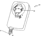
The plug body 20 that each accompanying drawing is schematically expressed an adapter pedestal 10 and connected.
Fig. 1 and 2 description adapter pedestal 10.Usually adapter pedestal 10 is made the molding of plastic material, adapter pedestal 10 comprises flat board 13, and described dull and stereotyped 13 have from the metallic conduction pin of 3 side-prominent projections of one.Be live wire pin and neutral line pin 11 and earth pin 12.By the another kind of mode of selecting, also can have only a pair of live wire pin and neutral line pin.Another selectable mode, described pin 12 can be a pseudo-pins plastic material or other non-conducting material.The socket of the adapter pedestal 10 of described embodiment is Britain's designs of standard, but will be understood that the structure of described pin can be Australia, the U.S. or other national structural style fully.Really, Fig. 3 and 4 plug body 20 just can be provided with a plurality of pedestals 10, and each pedestal can have the version that is applicable to country variant.
At the opposite side of flat board 13, be provided with the support ring 14 on plane, described support ring 14 forms the integral type molding with dull and stereotyped 13.It is inner also concentric with it that interior circle projection guide rail 7 and outer round guide 15 are positioned at support ring surface 14.Limit an annular channel 9 between two guide rails, this annular channel 9 has a pair of narrowed portion 8 relative at the diameter two ends.Be provided with electric connection terminal 17 in the bottom of narrowed portion 8.A wiring terminal is electrically connected to live wire pin or neutral line pin 11, and another electric connection terminal is electrically connected to another pin 11.The 3rd electric connection terminal 17 that links to each other with grounding pin 12 can also be arranged.
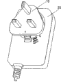
What Fig. 3 and 4 described is to press the interconnective plug body 20 of bayonet socket mode with adapter pedestal 10.Generally speaking, plug body 20 is made by several plastic mould pressing spares, these several moldings be screwed into, snap in fast with screw or ultra-sonic welded together, and stretch out a mains cord 21 from rubber tieing 22 of this back warp.
In other words, the size of opening 31 is just enough held the bayonet socket inserted sheet, and that bigger a pair of can not fitting in the less opening in 4 bayonet socket inserted sheets.
Inserted sheet receiving channel 29 along opening 31 be positioned at support ring 33 below.There is ramped surfaces bottom surface at each opening 31.
Along opening 31 location and what highlight opening 31 inside is a locking device, this locking device comprises interlocking joint tongue 24 and integrally formed with it actuation device 23.Interlocking joint tongue 24 is charged in the tongue groove 25, as shown in Figure 4.Refer again to Fig. 1, described outer round guide 15 comprises a pair of along the relative interlocking groove 18 of diametric(al), and when connecting these two parts by the bayonet socket mode, joint tongue 24 engagement fast enters in one of said interlocking groove 18.Actuation device 23 is whole building blocks of plug body 20, and in its each side pair of notches is arranged all, so that when actuation device 23 applies finger pressure, interlocking joint tongue 24 is moved down.Just when adding to this finger pressure, just can take the parts of interlocking apart.
During use, have like that as illustrated in Figures 5 and 6, parts 10 and 20 are fitted together, then, clockwise direction rotates adapter pedestal 10, up to the bayonet socket inserted sheet till each groove 29 all is supported on each end wall 28.At this moment, according to the selected direction shown in Fig. 7 or 8, interlocking joint tongue 24 is meshed fast enter in the interlocking groove 18.Then, can be with in the fixing flexible cord of parts insertion such as wall socket, plugboard or prolongation.
An alignment markers 30 is arranged on plug body 20, a pair of corresponding indicating device 34 is arranged on the adapter pedestal, be used for helping like that as illustrated in Figures 5 and 6 to aim at each parts.
Will be understood that for the conspicuous remodeling of those of ordinary skill in the art and replace and can not be considered to be beyond scope of the present invention.For example, can provide low pressure output to mains cord 21 at transformer of positioned internal of plug body 20.In addition, if, can adopt the insertion arrangement of other type without being meshing with each other of bayonet type.
And then the pedestal of obvious described Electric adapter is not necessarily leaveed no choice but by the direct contact pin form of admitting in the hole that connects socket.For example shown in Figure 9, described pedestal can have an extension cord 35 from extending here, at its far-end a standard plug 36 of for example admitting from wall socket or another extension cord is arranged.
Also have, can form described plug body with electric equipment, two adapter, multitap plate, transformer beam splitting box or analog integral type.
Claims (16)
1. an Electric adapter is used to have change the country that plug inserts the electrical network pin/socket layout of orientation, and it comprises:
Pedestal has from pedestal one side and extends to insert a plurality of conductive base pins of supporting socket; Also have and be positioned at and the electric connection terminal that with it be electrically connected corresponding on the pedestal opposite side with each conductive base pin, and a plurality of engageable rotating connecting part;
Main body, have a plurality of joint rotating connecting parts, be used for described each engageable rotating connecting part interoperation with pedestal, to guarantee that described main body is rotatably mounted on the pedestal according to one of two possible orientations, a described orientation is with respect to 180 ° of another oriented difference, described main body has a plurality of electric contacts, and the structure of each electric contact is suitable for so fixedly the time, making each electric connection terminal engagement of each electric contact and pedestal at main body and pedestal.
2. Electric adapter as claimed in claim 1, wherein, described main body is integrally formed on electric equipment, two adapter, multitap plate, the transformer box.
3. Electric adapter as claimed in claim 1, wherein, described pedestal has the mains cord that begins to extend from it, far-end at mains cord has a plug, plug has conductive base pin, be used for inserting the jack of the socket that connects, and each lead in mains cord of electric connection terminal wherein is electrically connected to each conductive base pin.
4. Electric adapter as claimed in claim 2, wherein, described pedestal has a plurality of conductive base pins that extend from pedestal one side, in the jack of the socket that connects in order to insertion, and a plurality of electric connection terminals are positioned on the opposite side of pedestal, be electrically connected accordingly with each conductive base pin.
5. an Electric adapter is used to have change the country that plug inserts the electrical network pin/socket layout of orientation, and it comprises:
Pedestal, have a plurality of electric connection terminals and a plurality of engageable rotating connecting part, wherein, described pedestal has the mains cord that begins to extend from it, far-end at mains cord has a plug, plug has conductive base pin, is used for inserting the jack of the socket that connects, and each lead in mains cord of electric connection terminal wherein is electrically connected to each conductive base pin.
Main body, have a plurality of joint rotating connecting parts, be used for described each engageable rotating connecting part interoperation with pedestal, to guarantee that described main body is rotatably mounted on the pedestal according to one of two possible orientations, a described orientation is with respect to 180 ° of another oriented difference, described main body has a plurality of electric contacts, and the structure of each electric contact is suitable for so fixedly the time, making each electric connection terminal engagement of each electric contact and pedestal at main body and pedestal.
6. an Electric adapter is used to have change the country that plug inserts the electrical network pin/socket layout of orientation, and it comprises:
Pedestal has a plurality of electric connection terminals and a plurality of engageable rotating connecting part, and the engageable rotating connecting part of wherein said pedestal comprises a plurality of inserted sheets that radially extend, and described each inserted sheet that radially extends has the ramped surfaces of along the circumferential direction extending; And
Main body, have a plurality of joint rotating connecting parts, be used for described each engageable rotating connecting part interoperation with pedestal, to guarantee that described main body is rotatably mounted on the pedestal according to one of two possible orientations, a described orientation is with respect to 180 ° of another oriented difference, described main body has a plurality of electric contacts, and the structure of each electric contact is suitable for so fixedly the time, making each electric connection terminal engagement of each electric contact and pedestal at main body and pedestal.
7. Electric adapter according to claim 6, wherein, the joint rotating connecting part of described main body comprises a plurality of openings, inserted sheet must could be realized being meshing with each other of described pedestal and main body by described opening.
8. Electric adapter according to claim 7, wherein, described each inserted sheet has different sizes, and described opening has corresponding different size, so that limit the admissible direction of orientation of described main body and pedestal when interconnecting.
9. an Electric adapter is used to have change the country that plug inserts the electrical network pin/socket layout of orientation, and it comprises:
Pedestal, described pedestal comprise an annular channel with a plurality of narrowed portions, and electric connection terminal is positioned in the narrowed portion of raceway groove, and described pedestal also comprises a plurality of engageable rotating connecting parts; And
Main body, have a plurality of joint rotating connecting parts, be used for described each engageable rotating connecting part interoperation with pedestal, to guarantee that described main body is rotatably mounted on the pedestal according to one of two possible orientations, a described orientation is with respect to 180 ° of another oriented difference, described main body has a plurality of electric contacts, and the structure of each electric contact is suitable for so fixedly the time, making each electric connection terminal engagement of each electric contact and pedestal at main body and pedestal.
10. Electric adapter as claimed in claim 9, wherein, described pedestal has the mains cord that begins to extend from it, far-end at mains cord has a plug, plug has conductive base pin, be used for inserting the jack of the socket that connects, and each lead in mains cord of electric connection terminal wherein is electrically connected to each conductive base pin.
11. an Electric adapter is used to have change the country that plug inserts the electrical network pin/socket layout of orientation, it comprises:
Pedestal has a plurality of electric connection terminals and a plurality of engageable rotating connecting part;
Main body, have a plurality of joint rotating connecting parts, be used for described each engageable rotating connecting part interoperation with pedestal, to guarantee that described main body is rotatably mounted on the pedestal according to one of two possible orientations, a described orientation is with respect to 180 ° of another oriented difference, described main body has a plurality of electric contacts, the biasing of each electrical contact springs is suitable for so fixedly the time, each electric connection terminal of each electric contact and pedestal being meshed with pedestal in main body to the structure of described each terminals and each electric contact.
12. Electric adapter as claimed in claim 11, wherein, described pedestal has a plurality of conductive base pins that extend from pedestal one side, in the jack of the socket that connects in order to insertion, and a plurality of electric connection terminals are positioned on the opposite side of pedestal, be electrically connected accordingly with each conductive base pin.
13. an Electric adapter is used to have change the country that plug inserts the electrical network pin/socket layout of orientation, it comprises:
Pedestal, described pedestal has a plurality of electric connection terminals, and they are connected with each conductor from the mains cord of Subject Extension; Described pedestal also has a plurality of engageable rotating connecting parts;
Main body, have a plurality of joint rotating connecting parts, be used for described each engageable rotating connecting part interoperation with pedestal, to guarantee that described main body is rotatably mounted on the pedestal according to one of two possible orientations, a described orientation is with respect to 180 ° of another oriented difference, described main body has a plurality of electric contacts, and the structure of each electric contact is suitable for so fixedly the time, making each electric connection terminal engagement of each electric contact and pedestal at main body and pedestal.
14. an Electric adapter, it comprises:
Pedestal has a plurality of electric connection terminals and a plurality of engageable bayonet socket link;
Main body, have a plurality of joint bayonet socket links, be used for described each engageable bayonet socket link interoperation with pedestal, to guarantee that described main body is rotatably fixed on the pedestal, described main body has a plurality of electric contacts, the structure of each electric contact is suitable at main body and pedestal so fixedly the time, make each electric connection terminal engagement of each electric contact and pedestal, the bayonet socket link of wherein said pedestal comprises a plurality of inserted sheets that radially extend, and described each inserted sheet that radially extends has the ramped surfaces of along the circumferential direction extending.
15. an Electric adapter, it comprises:
Pedestal has a plurality of electric connection terminals and a plurality of engageable rotating connecting part;
Main body, have a plurality of joint rotating connecting parts, be used for described each engageable rotating connecting part interoperation with pedestal, to guarantee that described main body is rotatably fixed on the pedestal, described main body has a plurality of electric contacts, the structure of each electric contact is suitable at main body and pedestal so fixedly the time, make each electric connection terminal engagement of each electric contact and pedestal, the engageable rotating connecting part of wherein said pedestal comprises a plurality of inserted sheets that radially extend, and described each inserted sheet that radially extends has the ramped surfaces of along the circumferential direction extending;
Locking device, when described main body and pedestal interconnected rotationally, described main body automatically was locked on pedestal by this locking device, but this needs manually decompression so that unclamp main body from pedestal.
16. an Electric adapter, it comprises:
Pedestal has a plurality of electric connection terminals and engageable rotating connecting part; Wherein said pedestal comprises an annular channel, and electric connection terminal is positioned in this raceway groove;
Main body, have a plurality of joint rotating connecting parts, be used for described each engageable rotating connecting part interoperation with pedestal, to guarantee that described main body is rotatably fixed on the pedestal, described main body has a plurality of electric contacts, the structure of each electric contact is suitable for so fixedly the time, making each electric connection terminal engagement of each electric contact and pedestal at main body and pedestal; And
Locking device, when described main body and pedestal interconnected rotationally, described main body automatically was locked on pedestal by this locking device, but this needs manually decompression so that unclamp main body from pedestal.
Applications Claiming Priority (2)
| Application Number | Priority Date | Filing Date | Title |
|---|---|---|---|
| GB0300098.1 | 2003-01-03 | ||
| GBGB0300098.1A GB0300098D0 (en) | 2003-01-03 | 2003-01-03 | Electrical adaptor |
Publications (2)
| Publication Number | Publication Date |
|---|---|
| CN1518169A CN1518169A (en) | 2004-08-04 |
| CN100449883C true CN100449883C (en) | 2009-01-07 |
Family
ID=9950640
Family Applications (1)
| Application Number | Title | Priority Date | Filing Date |
|---|---|---|---|
| CNB2004100012024A Expired - Fee Related CN100449883C (en) | 2003-01-03 | 2004-01-02 | power adapter |
Country Status (10)
| Country | Link |
|---|---|
| US (1) | US6942508B2 (en) |
| EP (1) | EP1437804B1 (en) |
| JP (2) | JP4508658B2 (en) |
| KR (1) | KR101015494B1 (en) |
| CN (1) | CN100449883C (en) |
| AT (1) | ATE456174T1 (en) |
| DE (1) | DE60331039D1 (en) |
| GB (1) | GB0300098D0 (en) |
| HK (1) | HK1067797A1 (en) |
| TW (1) | TWI303504B (en) |
Families Citing this family (41)
| Publication number | Priority date | Publication date | Assignee | Title |
|---|---|---|---|---|
| TWI262634B (en) * | 2005-09-16 | 2006-09-21 | Hon Hai Prec Ind Co Ltd | Power supply devices and electronic products using the same |
| US20100120278A1 (en) * | 2005-10-26 | 2010-05-13 | Yang chun-lian | Multi-angular power adapter |
| TWI273752B (en) * | 2006-02-07 | 2007-02-11 | Leader Electronics Inc | Power source plug with changeable direction |
| EP1830186A1 (en) * | 2006-03-01 | 2007-09-05 | ETH Zürich | High-throughput cell-based screening system |
| WO2007113541A2 (en) * | 2006-04-03 | 2007-10-11 | Thinplug Limited | Electrical plug with a rotatable pin |
| US7273384B1 (en) * | 2006-04-11 | 2007-09-25 | Modern Sense Limited | Universal battery charger and/or power adaptor |
| EP1845590B1 (en) * | 2006-04-11 | 2013-03-27 | Modern Sense Ltd | Universal battery charger and/or power adaptor |
| US20080064244A1 (en) * | 2006-09-08 | 2008-03-13 | Bryan Holland | Plug adapter with pivotally mounted prongs |
| IN2008CH00059A (en) * | 2007-01-08 | 2015-09-25 | Modern Sense Ltd | |
| JP4950694B2 (en) * | 2007-02-19 | 2012-06-13 | パナソニック株式会社 | Lamp socket and lighting fixture |
| TWM321168U (en) * | 2007-03-02 | 2007-10-21 | Billion Electric Co Ltd | Power adapter module with rotatable plug, power supply and electric apparatus with said power adapter module or said power supply |
| DE102007013502A1 (en) * | 2007-03-21 | 2008-09-25 | Illinois Tool Works Inc., Glenview | Extension cable and adapted pipe processing device |
| US20090225486A1 (en) | 2008-03-07 | 2009-09-10 | Belkin International, Inc. | Electrical Connector And Method Of Manufacturing Same |
| FR2928494A1 (en) * | 2008-03-07 | 2009-09-11 | Swiss Hitech Asia Ltd | Universal power supply adapter e.g. power plug, for connecting electrical apparatus on female connector, has housing to receive male connector, whose output connectors and contact studs of base are connected in final connection position |
| US8197260B2 (en) | 2008-03-07 | 2012-06-12 | Belkin International, Inc. | Electrical connector and method of manufacturing same |
| US7896702B2 (en) * | 2008-06-06 | 2011-03-01 | Apple Inc. | Compact power adapter |
| US7632137B1 (en) * | 2008-07-28 | 2009-12-15 | Cheng Uei Precision Industry Co., Ltd. | Power adapter |
| US7601023B1 (en) * | 2008-08-07 | 2009-10-13 | Cheng Uei Precision Industry Co., Ltd. | Power adapter |
| US7632119B1 (en) * | 2008-08-11 | 2009-12-15 | Cheng Uei Precision Industry Co., Ltd. | Power adapter |
| US8934261B2 (en) | 2008-12-23 | 2015-01-13 | Apple Inc. | Compact device housing and assembly techniques therefor |
| US7993164B2 (en) * | 2008-12-31 | 2011-08-09 | Hewlett-Packard Development Company, L.P. | Compact power adapter with interchangeable heads |
| TWM359782U (en) * | 2009-01-06 | 2009-06-21 | Unifive Technology Co Ltd | An adjustable power transformer |
| TWM359781U (en) * | 2009-01-06 | 2009-06-21 | Unifive Technology Co Ltd | A detachable power transformer |
| EP2276120B1 (en) * | 2009-07-10 | 2015-10-14 | BlackBerry Limited | Electrical charger |
| TWI385875B (en) * | 2009-10-07 | 2013-02-11 | Leader Electronics Inc | The plug can be changed in direction and replaceable power converter |
| TWI427875B (en) * | 2009-10-28 | 2014-02-21 | Powertech Ind Co Ltd | Rotatable and foldable electric plug connector |
| US8052441B2 (en) * | 2010-01-11 | 2011-11-08 | Hewlett-Packard Development Company, L.P. | Plug module |
| JP5515176B2 (en) * | 2010-05-21 | 2014-06-11 | 古河電工パワーシステムズ株式会社 | Connectors and connector sets |
| TWI399000B (en) * | 2010-07-26 | 2013-06-11 | Delta Electronics Inc | Electrnic device having rotary socket and rotary socket thereof |
| TWI413320B (en) * | 2010-12-14 | 2013-10-21 | Hon Hai Prec Ind Co Ltd | Power adapter with replaceable plug |
| TWM426181U (en) * | 2011-09-22 | 2012-04-01 | Leader Electronics Inc | Power plug apparatus capable of changing directions |
| CN103166037B (en) * | 2011-12-15 | 2017-02-01 | 富泰华工业(深圳)有限公司 | Mobile power source |
| DE102013003306B4 (en) * | 2013-02-28 | 2019-04-11 | Phoenix Contact Gmbh & Co. Kg | Connectors |
| TWM461255U (en) * | 2013-04-02 | 2013-09-01 | Hon Hai Prec Ind Co Ltd | Power adapter |
| WO2015111068A1 (en) | 2014-01-24 | 2015-07-30 | Remus Daniel | An electrical female receptacle with safety mechanism in multi-plug adapter and wall sockets |
| DE102014102930A1 (en) * | 2014-03-05 | 2015-09-10 | Phoenix Contact Gmbh & Co. Kg | Housing for a connector |
| TWI639283B (en) | 2017-08-08 | 2018-10-21 | 碩天科技股份有限公司 | Adapter and using method thereof |
| KR102557113B1 (en) * | 2018-04-14 | 2023-07-18 | 가부시키가이샤 아스타리스쿠 | Connectors and Connection Adapters |
| USD936020S1 (en) * | 2019-04-30 | 2021-11-16 | Design Pool Limited | Wall adapter |
| CN112490754A (en) * | 2019-09-12 | 2021-03-12 | 比亚迪股份有限公司 | Charging locking mechanism, charging port, vehicle and charging equipment |
| US11283224B1 (en) * | 2020-10-12 | 2022-03-22 | Ademco Inc. | Adapter mechanism |
Citations (4)
| Publication number | Priority date | Publication date | Assignee | Title |
|---|---|---|---|---|
| CN2253877Y (en) * | 1996-04-09 | 1997-05-07 | 周义雄 | Electric plug with rotation function |
| US5702259A (en) * | 1996-08-12 | 1997-12-30 | Lee; Chiu-Shan | Safety socket and plug arrangement |
| CN1248083A (en) * | 1998-09-11 | 2000-03-22 | 希布莱恩提克斯公司 | Socket adaptor |
| CN2519498Y (en) * | 2001-12-13 | 2002-10-30 | 陈苍意 | Rotary plug |
Family Cites Families (7)
| Publication number | Priority date | Publication date | Assignee | Title |
|---|---|---|---|---|
| TW269751B (en) | 1994-02-24 | 1996-02-01 | Asian Micro Sources Inc | Interchangeable plug device for power supply |
| US6139359A (en) * | 1999-04-08 | 2000-10-31 | Snap-On Tools Company | Cordless screwdriver and multi-position battery pack therefor |
| DE19932942A1 (en) * | 1999-07-14 | 2001-03-15 | Tyco Electronics Logistics Ag | RF right angle connector |
| GB2366087B (en) * | 2000-08-09 | 2004-05-26 | Chiu-Shan Lee | Universal electric adapter |
| US6669495B2 (en) * | 2000-11-06 | 2003-12-30 | Research In Motion Limited | Universal adapter with interchangeable plugs |
| KR100396207B1 (en) * | 2001-02-06 | 2003-09-03 | 김병준 | Adapter with rotary plug |
| TWI243519B (en) * | 2001-05-31 | 2005-11-11 | Primax Electronics Ltd | Socket which can be tightly connected with a plug |
-
2003
- 2003-01-03 GB GBGB0300098.1A patent/GB0300098D0/en not_active Ceased
- 2003-12-30 DE DE60331039T patent/DE60331039D1/en not_active Expired - Lifetime
- 2003-12-30 EP EP03258240A patent/EP1437804B1/en not_active Expired - Lifetime
- 2003-12-30 AT AT03258240T patent/ATE456174T1/en not_active IP Right Cessation
- 2003-12-31 US US10/749,964 patent/US6942508B2/en not_active Expired - Lifetime
-
2004
- 2004-01-02 TW TW093100066A patent/TWI303504B/en not_active IP Right Cessation
- 2004-01-02 KR KR1020040000050A patent/KR101015494B1/en not_active IP Right Cessation
- 2004-01-02 CN CNB2004100012024A patent/CN100449883C/en not_active Expired - Fee Related
- 2004-01-05 JP JP2004000622A patent/JP4508658B2/en not_active Expired - Fee Related
- 2004-12-21 HK HK04110105.7A patent/HK1067797A1/en not_active IP Right Cessation
-
2009
- 2009-04-10 JP JP2009095665A patent/JP2009187955A/en active Pending
Patent Citations (4)
| Publication number | Priority date | Publication date | Assignee | Title |
|---|---|---|---|---|
| CN2253877Y (en) * | 1996-04-09 | 1997-05-07 | 周义雄 | Electric plug with rotation function |
| US5702259A (en) * | 1996-08-12 | 1997-12-30 | Lee; Chiu-Shan | Safety socket and plug arrangement |
| CN1248083A (en) * | 1998-09-11 | 2000-03-22 | 希布莱恩提克斯公司 | Socket adaptor |
| CN2519498Y (en) * | 2001-12-13 | 2002-10-30 | 陈苍意 | Rotary plug |
Also Published As
| Publication number | Publication date |
|---|---|
| US20050074996A1 (en) | 2005-04-07 |
| US6942508B2 (en) | 2005-09-13 |
| GB0300098D0 (en) | 2003-02-05 |
| CN1518169A (en) | 2004-08-04 |
| EP1437804A2 (en) | 2004-07-14 |
| TW200417090A (en) | 2004-09-01 |
| KR101015494B1 (en) | 2011-02-22 |
| JP2004214206A (en) | 2004-07-29 |
| JP4508658B2 (en) | 2010-07-21 |
| JP2009187955A (en) | 2009-08-20 |
| KR20040062886A (en) | 2004-07-09 |
| EP1437804A3 (en) | 2005-11-02 |
| DE60331039D1 (en) | 2010-03-11 |
| ATE456174T1 (en) | 2010-02-15 |
| EP1437804B1 (en) | 2010-01-20 |
| TWI303504B (en) | 2008-11-21 |
| HK1067797A1 (en) | 2005-04-15 |
Similar Documents
| Publication | Publication Date | Title |
|---|---|---|
| CN100449883C (en) | power adapter | |
| US6669495B2 (en) | Universal adapter with interchangeable plugs | |
| US5684689A (en) | Interchangeable plug power supply with automatically adjusting input voltage receiving mechanism | |
| US7798825B1 (en) | Plug with connecting device | |
| US8400104B2 (en) | Gangable inductive battery charger | |
| TWI415348B (en) | Can replace the different plugs and can change the direction of the plug power conversion device | |
| US7396234B2 (en) | Electrical outlets | |
| US9028261B2 (en) | Snap electrical connector having a circumferential groove and prong interconnection | |
| CN104852225A (en) | Electrical and optical hybrid connector | |
| US4904195A (en) | Twist-lock female-male plug adapter | |
| US7108564B2 (en) | Convertible plug | |
| US20100130071A1 (en) | Socket assembly with sliding plate | |
| TW201427204A (en) | Connector having a protective cover and electronic device | |
| JP2021082585A (en) | Contact carrier for electrical plug connector and plug connector thereof | |
| CN106981801A (en) | Adapter assembly | |
| US20090081895A1 (en) | Universal adapter | |
| EP2648286A1 (en) | Power connector assembly and adapter plug with locking mechanism | |
| CN210957231U (en) | Conversion socket | |
| GB2450541A (en) | Wall socket for different plugs, which may provide different voltages | |
| CN203504254U (en) | Portable charger | |
| CN201122773Y (en) | Plug seat | |
| KR101698907B1 (en) | concent to enable easy check of plug insert direction | |
| CN218182613U (en) | XLR interface plug | |
| CN113258344B (en) | Socket type connector | |
| EP1571740A1 (en) | Electrical socket outlet device |
Legal Events
| Date | Code | Title | Description |
|---|---|---|---|
| C06 | Publication | ||
| PB01 | Publication | ||
| C10 | Entry into substantive examination | ||
| SE01 | Entry into force of request for substantive examination | ||
| C14 | Grant of patent or utility model | ||
| GR01 | Patent grant | ||
| CF01 | Termination of patent right due to non-payment of annual fee |
Granted publication date: 20090107 Termination date: 20180102 |
|
| CF01 | Termination of patent right due to non-payment of annual fee |