The related technical literature formerly of the application's invention is as follows.
Summary of the invention
In the structure example in the past shown in above-mentioned Figure 13 A~Figure 13 C, there is following problem, that is: when the crooked bounce (screen resilience) of the PFC11 that turns back to the backlight back side is very strong, can't suppress upspringing of FPC11 by adhesive tape is fixing, such shown in the A of Figure 13 B, in the installation region of white light-emitting diode 15 heaving of FPC11 being taken place and float, white light-emitting diode 15 takes place from tram skew (to the skew of the Z direction at light guide plate center), brightness takes place reduce.
In order to suppress heaving, floating of this FPC11, on the basis of scrutinizing the fixed position of fixing by double sticky tape 31, increase the area of adhesive tape, under the still insufficient situation of bed knife nonetheless, just need add a cover sheet metal etc., and these all become the reason that hinders LCD MODULE to realize miniaturization, slimming from the top of FPC11.
The present invention makes for the problem that solves above-mentioned conventional art, and the invention has the advantages that to provide the miniaturization that can seek liquid crystal indicator, the technology of slimming.
Above-mentioned advantage of the present invention and other advantage and new feature will obtain clearly by the description and the accompanying drawing of this instructions.
The summary of simple declaration representative content in the disclosed invention of the application is as follows.
(1): a kind of liquid crystal indicator comprises
LCD panel,
Be configured in the backlight of the rear side of above-mentioned LCD panel, and
The flex circuit application that one end is connected with the portion of terminal of above-mentioned LCD panel, wherein:
Above-mentioned backlight has frame shape moulded parts and light source;
Above-mentioned flex circuit application, by bending, its part is configured in the rear side of above-mentioned frame shape moulded parts outside the frame of above-mentioned frame shape moulded parts;
Above-mentioned light source is contained in the frame of above-mentioned frame shape moulded parts; And
Above-mentioned light source be positioned at above-mentioned flex circuit application bending part near, be installed in the face of above-mentioned flex circuit application at above-mentioned flex circuit application under by the state of bending on the face relative with above-mentioned LCD panel;
Above-mentioned flex circuit application has grooving around above-mentioned light source.
(2): in (1), above-mentioned frame shape moulded parts has the 1st sidewall, the 2nd sidewall and the 3rd sidewall, and wherein, the 1st sidewall is positioned at above-mentioned flex circuit application by a side of bending; The 2nd sidewall is positioned at the distolateral of above-mentioned the 1st sidewall; It is distolateral that the 3rd sidewall is positioned at another of above-mentioned the 1st sidewall, relative with above-mentioned the 2nd sidewall,
The above-mentioned grooving of above-mentioned flex circuit application comprises the 1st grooving, the 2nd grooving and the 3rd grooving, and wherein, above-mentioned the 1st grooving is than more close above-mentioned the 1st side wall side of above-mentioned light source, and along above-mentioned the 1st sidewall; Above-mentioned the 2nd grooving and above-mentioned the 3rd grooving are connected to the both ends of above-mentioned the 1st grooving, and respectively along above-mentioned the 2nd sidewall and above-mentioned the 3rd sidewall.
(3): in (1) or (2), above-mentioned flex circuit application by above-mentioned grooving separated portions, be secured at by double sticky tape on the face of rear side of above-mentioned frame shape moulded parts.
(4): from (1) to (3) any one, above-mentioned frame shape moulded parts has rear side opening at above-mentioned frame shape moulded parts, is used to insert the recess of above-mentioned light source.
(5): from (1) to (4) any one, above-mentioned flex circuit application is secured at by double sticky tape on the face of rear side of above-mentioned frame shape moulded parts.
(6): a kind of liquid crystal indicator comprises
LCD panel,
Be configured in the backlight of the rear side of above-mentioned LCD panel, and
The flex circuit application that one end is connected with the portion of terminal of above-mentioned LCD panel, wherein:
Above-mentioned backlight has frame shape moulded parts;
Above-mentioned flex circuit application is by bending, and its part is configured in the rear side of above-mentioned frame shape moulded parts;
Above-mentioned flex circuit application has electronic unit;
Above-mentioned frame shape moulded parts has the 1st sidewall, the 2nd sidewall and the 3rd sidewall, and wherein, the 1st sidewall is positioned at above-mentioned flex circuit application by a side of bending; The 2nd sidewall is positioned at the distolateral of above-mentioned the 1st sidewall; It is distolateral that the 3rd sidewall is positioned at another of above-mentioned the 1st sidewall, relative with above-mentioned the 2nd sidewall;
Above-mentioned the 2nd sidewall of above-mentioned frame shape moulded parts has rear side opening at above-mentioned frame shape moulded parts, is used to insert the recess of above-mentioned electronic unit.
(7): in (6), above-mentioned the 3rd sidewall of above-mentioned frame shape moulded parts has rear side opening at above-mentioned frame shape moulded parts, is used to insert the recess of above-mentioned electronic unit.
(8): in (6) or (7), above-mentioned recess is formed with a plurality of with predetermined interval.
(9): from (6) to (8) any one, the length of above-mentioned recess when the bearing of trend of the sidewall that is formed with above-mentioned recess is measured, is less than or equal to 10mm.
(10): from (6) to (9) any one, the length of above-mentioned recess when the bearing of trend of the sidewall that is formed with above-mentioned recess is measured, is less than or equal to 5mm.
(11): from (6) to (10) any one, above-mentioned backlight has light conductor;
Above-mentioned the 2nd sidewall of above-mentioned frame shape moulded parts and above-mentioned the 3rd sidewall, when supposition does not have above-mentioned recess, part 1, part 2 and the 3rd part with frame stepped variation, the above-mentioned part 1 of frame amplitude ratio of the above-mentioned frame shape moulded parts of above-mentioned part 2 is big, and the above-mentioned part 2 of frame amplitude ratio of the above-mentioned frame shape moulded parts of above-mentioned the 3rd part is big;
Above-mentioned LCD panel is contained in above-mentioned part 1;
Above-mentioned light conductor is contained in above-mentioned the 3rd part;
Be used to insert the above-mentioned recess of above-mentioned electronic unit, be formed on above-mentioned the 3rd part.
(12): from (6) to (11) any one, above-mentioned backlight has reflector plate,
Above-mentioned reflector plate is fixed on the rear side of above-mentioned frame shape moulded parts.
(13): from (6) to (12) any one, above-mentioned flex circuit application is secured at by double sticky tape on the face of rear side of above-mentioned frame shape moulded parts.
(14): in (12), above-mentioned flex circuit application is when carrying out viewed in plan, and it is secured on the above-mentioned frame shape moulded parts in the zone in the outside of above-mentioned reflector plate.
(15): in (12), above-mentioned reflector plate, the part in the zone that is covered by above-mentioned flex circuit application, the notch of showing out with the rear side that makes above-mentioned moulded parts,
At above-mentioned notch, above-mentioned flex circuit application is secured on the above-mentioned frame shape moulded parts.
(16): a kind of liquid crystal indicator comprises
LCD panel,
Be configured in the backlight of the rear side of above-mentioned LCD panel, and
The flex circuit application that one end is connected with the portion of terminal of above-mentioned LCD panel, wherein:
Above-mentioned backlight has frame shape moulded parts and light source;
Above-mentioned flex circuit application, by bending, its part is disposed at the rear side of above-mentioned frame shape moulded parts outside the frame of above-mentioned frame shape moulded parts;
Above-mentioned frame shape moulded parts has the 1st sidewall, the 2nd sidewall and the 3rd sidewall, and wherein, the 1st sidewall is positioned at above-mentioned flex circuit application by a side of bending; The 2nd sidewall is positioned at the distolateral of above-mentioned the 1st sidewall; It is distolateral that the 3rd sidewall is positioned at another of above-mentioned the 1st sidewall, relative with above-mentioned the 2nd sidewall;
Above-mentioned light source is contained in the frame of above-mentioned frame shape moulded parts; And
Above-mentioned light source be positioned at above-mentioned flex circuit application bending part near, be installed in the face of above-mentioned flex circuit application at above-mentioned flex circuit application under by the state of bending on the face relative with above-mentioned LCD panel;
Above-mentioned flex circuit application has electronic unit;
Above-mentioned flex circuit application has grooving around above-mentioned light source;
Above-mentioned the 2nd sidewall of above-mentioned frame shape moulded parts has rear side opening at above-mentioned frame shape moulded parts, is used to insert the recess of above-mentioned electronic unit.
(17): in (16), the above-mentioned grooving of above-mentioned flex circuit application comprises the 1st grooving, the 2nd grooving and the 3rd grooving, and wherein, above-mentioned the 1st grooving is than more close above-mentioned the 1st side wall side of above-mentioned light source, and along above-mentioned the 1st sidewall; Above-mentioned the 2nd grooving and above-mentioned the 3rd grooving are connected to the both ends of above-mentioned the 1st grooving, respectively along above-mentioned the 2nd sidewall and above-mentioned the 3rd sidewall.
(18): in (16) or (17), above-mentioned flex circuit application by above-mentioned grooving separated portions, be secured at by double sticky tape on the face of rear side of above-mentioned frame shape moulded parts.
(19): from (16) to (18) any one, above-mentioned frame shape moulded parts has rear side opening at above-mentioned frame shape moulded parts, is used to insert the recess of above-mentioned light source.
(20): from (16) to (19) any one, above-mentioned the 3rd sidewall of above-mentioned frame shape moulded parts has rear side opening at above-mentioned frame shape moulded parts, is used to insert the recess of above-mentioned electronic unit.
(21): any one, be used to insert the above-mentioned recess of above-mentioned electronic unit, be formed with a plurality of with predetermined interval from (16) to (20).
(22): any one, be used to insert the length of the above-mentioned recess of above-mentioned electronic unit, when the bearing of trend of the sidewall that has formed the above-mentioned recess that is used to insert above-mentioned electronic unit is measured, be less than or equal to 10mm from (16) to (21).
(23): any one, be used to insert the length of the above-mentioned recess of above-mentioned electronic unit, when the bearing of trend of the sidewall that has formed the above-mentioned recess that is used to insert above-mentioned electronic unit is measured, be less than or equal to 5mm from (16) to (22).
(24): from (16) to (23) any one, above-mentioned backlight has light conductor;
Above-mentioned the 2nd sidewall of above-mentioned frame shape moulded parts and above-mentioned the 3rd sidewall, when the above-mentioned recess of above-mentioned electronic unit is not inserted in supposition, part 1, part 2 and the 3rd part with frame stepped variation, the above-mentioned part 1 of frame amplitude ratio of the above-mentioned frame shape moulded parts of above-mentioned part 2 is big, and the above-mentioned part 2 of frame amplitude ratio of the above-mentioned frame shape moulded parts of above-mentioned the 3rd part is big;
Above-mentioned LCD panel is contained in above-mentioned part 1;
Above-mentioned light conductor is contained in above-mentioned the 3rd part;
Be used to insert the above-mentioned recess of above-mentioned electronic unit, be formed on above-mentioned the 3rd part.
(25): from (16) to (24) any one, above-mentioned backlight has reflector plate,
Above-mentioned reflector plate is fixed on the rear side of above-mentioned frame shape moulded parts.
(26): from (16) to (25) any one, above-mentioned flex circuit application is secured at by double sticky tape on the face of rear side of above-mentioned frame shape moulded parts.
(27): in (25), above-mentioned flex circuit application, when carrying out viewed in plan, the zone in the outside of above-mentioned reflector plate is secured on the above-mentioned frame shape moulded parts.
(28): in (25), above-mentioned reflector plate, the part in the zone that is covered by above-mentioned flex circuit application, the notch of showing out with the rear side that makes above-mentioned moulded parts,
At above-mentioned notch, above-mentioned flex circuit application is secured on the above-mentioned frame shape moulded parts.
In addition, the represented structure in (1)~(28), but be an example, in the scope that does not break away from technological thought of the present invention, can carry out various changes.
The effect that simple declaration can obtain by the representational content in the disclosed invention of the application is as follows.
According to liquid crystal indicator of the present invention, can realize miniaturization, slimming.
Embodiment
Below, embodiments of the present invention will be described in detail with reference to the accompanying drawings.
In addition, the institute's drawings attached being used for illustrating embodiment has the identical label of giving of identical function, and the repetitive description thereof will be omitted.
The LCD MODULE of embodiments of the invention is the LCD MODULE of the TFT form of the compact liquid crystal panels that has 240 * 320 * 3 left and right sides number of sub-pixels in colour shows, is used as the display part of mobile device such as mobile phone.
[embodiment 1]
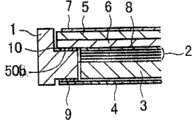
Figure 1A~Fig. 1 C is the figure of the LCD MODULE of expression embodiments of the invention 1, Figure 1A is from the observed figure of upside (LCD panel side, front face side, observer's side), Figure 1B is observed from the side figure, and Fig. 1 C is from the observed figure of downside (light guide plate side, rear side, inboard).Fig. 2 is the sectional view of expression along the cross-section structure of A-A ' line of cut of Fig. 1 C.
In the present embodiment, backlight has optical sheet set 2, light guide plate 3, be disposed at the reflector plate 4 of downside of light guide plate (light conductor) 3 and the white light-emitting diode 15 that is disposed at the side of light guide plate 3, wherein, this optical sheet set 2 is by down diffusion disk, 2 lens (lenssheet) and go up diffusion disk and constitute, the optical sheet set 2 in the backlight of present embodiment, light guide plate 3, reflector plate 4 with arranged in order shown in Figure 2 in moulded parts 1.
LCD panel, with be provided with pixel electrode, thin film transistor (TFT) etc. glass substrate (being also referred to as TFT substrate, active-matrix substrate) 6, to separate predetermined gap ground overlapping with the glass substrate (being also referred to as counter substrate) 5 that is formed with color filter etc., utilization is set to the seal of frame shape near the circumference between this two substrates, two substrates is fit together, and liquid crystal is enclosed in the inboard of enclosing the seal mouthful between two substrates from the liquid crystal of the part that is arranged at seal, seal, and then paste Polarizer (7,8) in the outside of two substrates and constitute.
Like this, become liquid crystal and be clamped in structure between a pair of substrate.In addition, the material of substrate only need be that the substrate of insulativity gets final product, and is not limited to glass, also can be plastics etc.And color filter also can not be arranged at the counter substrate side but be arranged at the TFT substrate-side.For monochrome the time, do not need color filter.If the liquid crystal indicator of preface (field sequential) mode can not be provided with color filter, and use 3 color light source to substitute white light-emitting diode.
If the LCD panel of TN mode or VA mode, opposite electrode is arranged at the counter substrate side.If the IPS form, opposite electrode is arranged at the TFT substrate-side.
In addition, because the inner structure of the present invention and liquid crystal board is irrelevant, therefore, omit detailed description to the inner structure of liquid crystal board.And then no matter the present invention is that the liquid crystal board of which type of structure can both be suitable for.
In the LCD MODULE of present embodiment, the white light-emitting diode 15 that backlight is used is installed on the FPC, and, with this FPC11 bending,, be fixed in double sticky tape 31 on the face of rear side of moulded parts 1 around the back side to backlight.Herein, FPC11 is by bending outside the frame of frame shape moulded parts 1.White light-emitting diode 15 be positioned at FPC11 bending part near, and this white light-emitting diode 15 be installed on FPC11 by the state of bending under in the face of FPC11 on the face relative with LCD panel, and be housed inside in the frame of moulded parts 1.In addition, though do not illustrate, be formed with the recess of side opening overleaf at frame shape moulded parts 1, white light-emitting diode 15 inserts these recesses.
Present embodiment is characterised in that: in the zone that white diode 15 is installed of FPC11, around white light-emitting diode 15, formed grooving 21.Herein, this grooving is made of part 1 (the 1st grooving) 21a, part 2 (the 2nd grooving) 21b and the 3rd part (the 3rd grooving) 21c.
The part 1 21a of grooving 21 is being arranged in FPC1 than white diode 15 more close frame shape moulded parts 1 by the sidewall of a side of bending (figure is a short brink) (the 1st sidewall of the present invention) side, along the sidewall of short brink and form.In addition, part 2 21b and the 3rd part 21c connect the both ends of part 1 21a respectively, separately along the sidewall (the 2nd sidewall of the present invention and the 3rd sidewall) of 2 long sides at the two ends of the sidewall that is positioned at short brink and form.
, be secured at by double sticky tape 32 on the face of rear side of frame shape moulded parts 1 from the FPC11 separated portions by grooving 21.The position of double sticky tape 32 can be the arbitrary orientation in all around of white light-emitting diode 15.
According to present embodiment, utilize grooving 21, the zone of the periphery of white light-emitting diode 15 among the FPC11 begins partly separated fixingly from the bending part of FPC11, therefore, become the influence springback that is difficult to directly be subjected to FPC integral body.Thus, can avoid floating of white light-emitting diode 15, can prevent the problem that brightness reduces, can obtain stable brightness.
And then, as long as can avoid the influence springback of FPC11, prevent that white light-emitting diode 15 from from the tram skew, just can make the bending radius of FPC11 become minimum, therefore, can design the physical dimension of LCD MODULE with the size of minimum.
And owing to form the structure of FPC11 with minimum radius, therefore, the area of FPC integral body diminishes, and can reduce cost.And,,, can reduce cost with regard to not needing constitutional detail such as sheet metal if only with double sticky tape fixing FPC11 just.
In addition, in above-mentioned each patent documentation, disclose the technology that on FPC, forms grooving.But, in these patent documentations, openly do not avoid the influence springback of FPC11, prevent the content of white light-emitting diode 15 from the tram skew.
[embodiment 2]
Fig. 3 A~Fig. 3 B is the figure of the LCD MODULE of expression embodiments of the invention 2, and Fig. 3 A is from the observed figure of upside (LCD panel side, front face side, observer's side), and Fig. 3 B is from the observed figure of downside (light guide plate side, rear side, inboard).Fig. 4 A is illustrated in the figure that has launched the state of FPC11 among Fig. 3 B.
In the LCD MODULE of present embodiment, also similarly to Example 1, the white light-emitting diode 15 that backlight is used is installed on the FPC, and, with this FPC11 bending,, be fixed in double sticky tape 31 on the face of rear side of moulded parts 1 around the back side to backlight.Herein, FPC11 is by bending outside the frame of frame shape moulded parts 1.White light-emitting diode 15 be located at FPC11 bending part near, and this white light-emitting diode 15 be installed on FPC11 by the state of bending under in the face of this FPC11 on the face relative with LCD panel, and be housed inside in the frame of moulded parts 1.Be formed with the recess 16 of side opening overleaf at frame shape moulded parts 1, white light-emitting diode 15 inserts this recess 16.
Same with the foregoing description, in the zone that white diode 15 is installed of FPC11, around white light-emitting diode 15, form grooving 21.Herein, this grooving is made of part 1 21a, part 2 21b and the 3rd part 21c.
In addition, omitted diagram, from the FPC11 separated portions, be secured at by double sticky tape (32 among Fig. 1 C) on the face of rear side of frame shape moulded parts 1 by grooving 21.
In the present embodiment, also be to utilize grooving 21, the zone of the periphery of white light-emitting diode 15 among the FPC11 begins partly separated fixingly from the bending part of FPC11, therefore, become the influence springback that is difficult to directly be subjected to FPC integral body.For this reason, can avoid floating of white light-emitting diode 15, can prevent the problem that brightness reduces, can obtain stable brightness.
Thus, according to present embodiment, also can make the bending radius of FPC11 become minimum, can design the physical dimension of LCD MODULE with the size of minimum, therefore, the area of FPC integral body diminishes, and can reduce cost.
And,,, can reduce cost with regard to not needing constitutional detail such as sheet metal if only with double sticky tape fixing FPC11 just.
Fig. 5 is the sectional view of expression along the cross-section structure of A-A ' line of cut of Fig. 3 A, and Fig. 6 is the sectional view of expression along the cross-section structure of B-B ' line of cut of Fig. 3 A.
In the present embodiment, backlight and the foregoing description are same, have optical sheet set 2, light guide plate 3, be disposed at the reflector plate 4 of downside of light guide plate 3 and the white light-emitting diode 15 that is disposed at the side of light guide plate 3, wherein, this optical sheet set 2 is by descending diffusion disk, 2 lens and go up diffusion disk to constitute.
Optical sheet set 2 is not limited to 4 such chip architectures of present embodiment.For example, also can be for not being to use 2 diffusion disks, and only used 1 structure.And, also can be for not using 2 lens (prismatic lens), and only used 1 structure.In addition, also can be by such as form grooves in light guide plate 3, making it to have concurrently the function of lens, and omit lens.Therefore, optical sheet set 2 also can be 1 optical sheet.And, also can use diffusion disk, lens optical sheet in addition.Based on above content, optical sheet set 2 also can be replaced at least 1 optical sheet.
White light-emitting diode 15 is installed on the FPC11, is configured in the recess 16 that is formed at frame shape moulded parts 1.Herein, reflector plate 4 is connected (perhaps bonding) and is fixed on the moulded parts by double sticky tape (stickup parts) 9.
Fig. 7 A~Fig. 7 B is the figure that is used to illustrate the shape of moulded parts shown in Figure 5.Fig. 7 A is the figure from the observed moulded parts shown in Figure 5 of upside (LCD panel side), and Fig. 7 B is the figure from the observed moulded parts shown in Figure 5 of downside (light guide plate side).
Shown in Fig. 7 A~Fig. 7 B, the moulded parts 1 of present embodiment for removing the bottom surface, has the structure of peristome at central portion, and promptly section shape is the box-shaped body (perhaps cylindrical body) of roughly 4 limit shape shapes.Thus, reflector plate 4 is secured at the rear side of frame shape moulded parts 1.
In present embodiment and the foregoing description 1, the frame width of cloth of making the moulded parts 1 around the light guide plate 3 makes it structure near the light guide plate side by methods such as thickenings.That is, in present embodiment and the foregoing description 1,2 limits of moulded parts 1 long side of moulded parts 1 (preferred) (with the limit of the plane of incidence quadrature of light guide plate 3) has part 1, part 2 and the 3rd part with relative edge's the stepped variation in interval.
At this, part 2 is (the B part of Fig. 5) narrower than part 1 (the A part of Fig. 5) with the interval relative edge, and the interval with the relative edge of the 3rd part (the C part of Fig. 5) is narrower than part 2.Form the 1st stage portion (50b) by part 1 A and part 2 B.
The edge part of the glass substrate 6 of the downside of LCD panel is by double sticky tape (stickup parts) the 10 supported stage portion 50b that are fixed in moulded parts 1.
And, forming the 2nd stage portion 51 by part 2 B and the 3rd portion C, optical sheet set 2 is supported on this stage portion 51.Light guide plate 3 is configured in the inboard of the 3rd portion C.
At the downside of this light guide plate 3, the peristome ground of covering molded piece 1 configuration reflector plate 4.
In the present embodiment, the end of the Polarizer 8 of downside is positioned at the 2nd stage portion 51.That is, the end of the Polarizer 8 of downside will be overlapping with the 2nd stage portion 51 when carrying out viewed in plan.
In the present embodiment, as the method for the inwall that makes moulded parts 1, both can be the method that partly increases the thickness of moulded parts 1 near light guide plate 3, also can be the method that under the state that keeps the identical frame width of cloth, inner wall position is inwards moved.
From the angle of permanance, preferably as shown in Figure 5, the frame amplitude ratio part 1 A of the frame shape moulded parts 1 of part 2 B is big, and the frame amplitude ratio part 2 B of the frame shape moulded parts 1 of the 3rd portion C is big.
Be contained in part 1 A by making LCD panel, light guide plate 3 is contained in the structure of the 3rd portion C, can dwindle the area of light guide plate 3.Even the brightness of white light-emitting diode 15 is identical, the area of (light guide plate 3 top) diminishes as long as the light emergence face of light guide plate, just improves the brightness of each unit area.Therefore, according to present embodiment, can obtain the backlight of high brightness.
So, present embodiment can also improve brightness on the basis of the slimming that has realized LCD MODULE.
In addition, in the present embodiment, be supported in the optical sheet set 2 on the stage portion 51, only need be at least 1 optical sheet and get final product.
Fig. 8 be the expression present embodiment LCD MODULE variation want portion's sectional view.
For example, also can be as shown in Figure 8, on stage portion 51, the last diffusion disk in the support of optical sheet group 2, other optical sheet (2 lens, diffusion disk) down in the inboard of the 3rd part, is configured on the light guide plate 3.
, as shown in Figure 8, the last diffusion disk in the optical sheet set 2 is supported on the stage portion 51, be in order to prevent that foreign material etc. from entering the inboard of the 3rd portion C herein.
In addition, the structure of optical sheet set 2 is not limited to above-mentioned structure, if on stage portion 51 at least 1 optical sheet of configuration, the sheet number of optical sheet that is disposed at the inboard of the 3rd portion C does not have special restriction.
By the embodiment of Fig. 5, Fig. 8 explanation, be the structure of the long side that relates to frame shape moulded parts 1, and, also can as shown in Figure 6 the 3rd portion C be set for short brink.In addition, a side of configuration white light-emitting diode 15 similarly forms stage portion 50a with stage portion 50b in the short brink of moulded parts.It is wideer than stage portion 50b that this stage portion 50a forms width, in the inboard of this stage portion 50a, accommodates white light-emitting diode 15.
In the present embodiment, also FPC11 is fixed around (bending) to the rear side of backlight.At this moment, with FPC11 around to the rear side of backlight fixedly the time, at least a portion that can will be installed in the electronic unit on the FPC is contained in the moulded parts 1.
That is, can shown in Fig. 7 B, in moulded parts 1, be formed on the open recess (61,62) of downside (rear side), at least a portion in the electronic unit that is installed on the FPC11 is contained in this recess (61,62).In addition, in Fig. 7 B, represented to have the situation of the recess (61,62) of bottom, but therefore the optional structure in bottom, as the electronic unit accommodation section, also can be the structure (through hole) that does not have the frame shape of bottom as the electronic unit accommodation section.
In the electronic unit on being installed on this FPC11, comprise the electronic unit that to adjust setting (Vcom of setting that for example is used to adjust reference voltage (perhaps opposed electrode voltage) Vcom of LCD panel adjusts the semi-fixed resistance element 14 of usefulness).
In the present embodiment, with FPC11 around to the rear side of backlight fixedly the time, be positioned at Vcom adjust usefulness semi-fixed resistance element 14 above FPC11 on form through hole 30.When having the bottom, on moulded parts 1, also form through hole 30 in the electronic unit accommodation section of moulded parts 1.In addition, be when not having the structure of frame shape of bottom in the electronic unit accommodation section of moulded parts 1, the effect of himself performance through hole.Thus, as shown in Figure 3A, when the LCD panel side is observed liquid crystal indicator, the electronic unit (Vcom adjusts the semi-fixed resistance element 14 of usefulness) that can adjust setting, be configured in than being formed at through hole 30 on the FPC11 more by the position of lining, and with through hole 30 position overlapped.
Thus, even under the assembling completion status of liquid crystal indicator, also can adjust the semi-fixed resistance element 14 that Vcom adjusts usefulness.And, can while observe image adjustment, therefore, also have the easier advantage of adjusting at the LCD panel display image.In addition, be positioned at the position of more leaning on the lining than the through hole 30 of FPC11, therefore, can be protruding to front face side, can realize slimming owing to can adjust the electronic unit of setting.
As described above, the LCD MODULE that mobile phone is used, increased FPC11 around the structure of fixing to the rear side of backlight, when with FPC11 with least radius from the portion of terminal of LCD panel around to the structure at the back side time, FPC11 has stronger screen resilience, therefore, need be careful the maintenance method of FPC11.
In the present embodiment, pay close attention to the zone of fixation reflex sheet 4, this part also is used for the fixing of FPC11.
Fig. 4 B is the figure that is used for the reflector plate 4 shown in the key diagram 4A.Shown in Fig. 4 B, the reflector plate 4 of present embodiment, the some in the zone that is covered by FPC11 has the notch (part of representing with oblique line) of the face of the rear side of exposing moulded parts 1 in Fig. 4 B.And shown in Fig. 4 A, FPC11 is adhesively fixed on the surface of the moulded parts 1 that exposes from this notch by double sticky tape (adhering part) 31.
And then, on the face of the rear side of moulded parts 1, form jut (17,18), and, the through hole (19,20) that inserts this jut (17,18) formed at FPC11.Thus, the location becomes easy.
In the present embodiment, by the jut (17,18) of moulded parts 1 being inserted the through hole (19,20) of FPC11, alleviated the screen resilience of FPC11.
In the present embodiment, as shown in Figure 3A, on the face of the LCD panel side of moulded parts 1, form jut 25, this jut 25 inserts the through hole that is formed on FPC11, and FPC11 is positioned.
So, in the present embodiment, FPC11 is not fixed on the reflector plate 4 by double sticky tape or adhering part, therefore, in hot environment, temperature variation environment, it is bad to suppress brightness disproportionation that the fold etc. by reflector plate 4 causes etc.
In addition, by having avoided reflector plate 4, the thickness of the double sticky tape 31 of the FPC11 that is adhesively fixed does not influence the gross thickness of LCD MODULE, therefore, as double sticky tape 31, can select the adhesive tape of strong bonding force, can prevent the generation of heaving of FPC11 central portion.
Thus, present embodiment can be realized miniaturization, the slimming of the LCD MODULE that mobile phone is used.
In the present invention, on the face of the rear side by FPC11 being sticked on moulded parts 1, compare, can suppress heaving of FPC11 with the situation of the side that sticks on moulded parts 1.And, as Fig. 4 B, as shown in Figure 5, by not with reflector plate 4 position overlapped, FPC11 sticks on the face of rear side of moulded parts 1, can correspondingly reduce the thickness of reflector plate 4 and the double sticky tape 9 that is used to paste reflector plate 4, realizes slimming.Thus, be used to paste the double sticky tape 31 of FPC11, can use the double sticky tape thicker than the double sticky tape 9 that is used to paste reflector plate 4, fixedly the power of FPC11 can be enhanced to the screen resilience that is enough to tackle FPC11.
And, owing to be not that FPC11 is sticked on the reflector plate 4, therefore, have the advantage of the distortion that can prevent reflector plate 4.In addition, the position of only having carried out stickup described herein (places of configuration stickup parts) have reflector plate 4 and FPC11 overlapping areas in other parts in addition.
Herein, in the moulded parts 1 of frame shape, will be positioned at FPC11 by the sidewall of a side of bending as the 1st sidewall, the one distolateral sidewall that will be positioned at the 1st sidewall is as the 2nd sidewall, to be positioned under another distolateral, relative sidewall situation of the 1st sidewall as the 3rd sidewall with the 2nd sidewall, preferably, FPC11 is secured at the zone (being provided with the zone of double sticky tape 31) on the face of rear side of moulded parts 1, along the 2nd sidewall or along the size of the direction of the 3rd sidewall, compare with size, have long shape along the direction of the 1st sidewall.That is, the shape of double sticky tape 31, the direction of (preferably quadrature) in fact of intersecting at the bearing of trend with bending part has long shape.This is that the screen resilience of FPC11 acts on the cause towards the direction of bending part very doughtily because in the position that is provided with double sticky tape 31 of Fig. 4 A.
In Fig. 4 A, have following advantage, that is: because reflector plate 4 is formed with notch, therefore can use double sticky tape 31 in wideer scope.But, under situation, can notch be set at reflector plate 4 for the frame fabric width as illustrating by Fig. 5, Fig. 8 yet.In this case, can use the roughly reflector plate 4 of rectangular shaped.
In addition, in Fig. 5, the periphery that illustrates in grooving portion also is pasted with the structure of reflector plate 4 by double sticky tape 9, but the invention is not restricted to such structure.For example, also can make in grooving portion periphery and zone (distance of bending part is less than or equal to the zone apart from d in Fig. 4 A), not have the structure that reflector plate 4 is secured at the zone on the moulded parts 1 than the more close bending part of grooving portion.In this case, reflector plate 4 is not pasted in the zone that is less than or equal to apart from d, covers and replace by FPC11, therefore what problem can not take place.Thus, even under the not abundant situation (for example, a frame narrow situation) in the space of pasting reflector plate 4, also can be suitable for the present invention.Obviously, also go for situation at Fig. 5, frame fabric width illustrated in fig. 8.
Such design also goes for not having the situation of notch on reflector plate 4.If this is carried out general explanation, then only be required to be following structure and get final product, that is: in the long limit of reflector plate 4,, have reflector plate 4 and be secured at zone on the moulded parts 1 from the distance of dogleg section zone greater than distance d; In the long limit of reflector plate 4, from the distance of dogleg section zone, there is not reflector plate 4 to be secured at zone on the moulded parts 1 less than distance d, reflector plate 4 is covered by FPC11.Thus, even under the not abundant situation (for example, a frame narrow situation) in the space of pasting reflector plate 4, also can be suitable for the present invention.In addition, also can substitute in distance and not use the structure of double sticky tape 9, and use than structure at the narrow double sticky tape 9 of the width of employed double sticky tape 9 in the zone of distance greater than distance d of dogleg section less than the zone of distance d from dogleg section.
[embodiment 3]
In the foregoing description 2, be that electronic units such as resistance, electric capacity are installed on the face relative with LCD panel among the FPC11, and in moulded parts 1, be positioned at the inboard that FPC11 is contained in electronic unit by the part of a side of bending moulded parts 1.
For this reason, under the situation of the structure of the foregoing description 2, need guarantee the spatial accommodation of electronic unit in moulded parts, for this reason, it is big that the planar dimension of LCD MODULE integral body becomes.
Present embodiment is the embodiment that is used to address this problem.
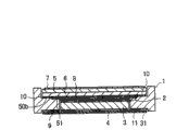
Fig. 9 A~Fig. 9 B is the figure of schematic configuration of the LCD MODULE of expression embodiments of the invention 3, Fig. 9 A is from the observed figure of upside (LCD panel side, front face side, observer's side), and Fig. 9 B is from the observed figure of downside (light guide plate side, rear side, inboard).
In the LCD MODULE of present embodiment, also be that the white light-emitting diode 15 that backlight is used is installed on the FPC, and, with this FPC11 bending,, be fixed in double sticky tape 31 on the face of rear side of moulded parts 1 around the back side to backlight.Herein, FPC11 is by bending outside the frame of frame shape moulded parts 1.White light-emitting diode 15 be positioned at FPC11 bending part near, and this white light-emitting diode 15 be installed on FPC by the state of bending under in the face of FPC11 on the face relative with LCD panel, and be housed inside in the frame of moulded parts 1.In addition, though do not illustrate, be formed with the recess of side opening overleaf at frame shape moulded parts 1, white light-emitting diode 15 inserts these recesses.
And, shown in Fig. 9 A~Fig. 9 B, in the present embodiment, with among the FPC11 in the width widen of FPC11 relative part with LCD panel under by the state of bending, make it to become the size that approaches the moulded parts width.On this basis, the rear side of dividing at the long leg of moulded parts 1 is provided with recess, and electronic unit 22 is installed in this recess, and this electronic unit 22 is installed on the face of moulded parts side of FPC11.
Figure 10 is the signal oblique view that is used to illustrate the recess of the rear side that the long leg that is formed on moulded parts 1 in the present embodiment divides, and Figure 11 is the sectional view of expression along the cross-section structure of A-A ' line of cut of Fig. 9 A.
These figure can be clear and definite, between recess 23 that is formed at moulded parts 1 and light guide plate 3, retains the wall that moulded parts 1 is arranged.
In order fully to guarantee to form the zone of recess 23, preferably, frame shape moulded parts 1 when supposition does not have recess, as Fig. 5 of embodiment 2, illustrated in fig. 8, have frame the stepped part 1 A that broadens, part 2 B and the 3rd portion C of moulded parts.And, preferably form recess 23 in the 3rd the wideest portion C of the frame width of cloth.In addition, be contained in part 1 A by making LCD panel, light conductor is contained in the structure of the 3rd portion C, also can obtain the effect that brightness is promoted as explanation among the embodiment 2.
Herein, preferred recess 23 forms a plurality of with predetermined interval.Consider the intensity of moulded parts 1, the length of per 1 recess 23 (T of Figure 10) preferably is less than or equal to 10mm when the bearing of trend of the sidewall that is formed with recess 23 is measured, more preferably be less than or equal to 5mm.In addition, if moulded parts 1 has enough intensity, also can make recess 23 be formed on moulded parts 1 long limit Zone Full or be formed on half the zone on long limit.
Recess 23 both can only be formed on one in 2 relative long limits, also can be formed on the two.
Figure 12 is the sectional view of expression along the variation of the cross-section structure of A-A ' line of cut of Fig. 9 A.
Shown in Figure 12 A,, also the recess 23 that is formed on moulded parts 1 can be processed into awl (taper) shape if can guarantee moulded parts 1 shapable thickness or can guarantee the intensity of moulded parts 1.
So,, the housing region of electronic unit is formed on the long leg branch of moulded parts 1, therefore, can shortens the length (length shown in the B of Fig. 9 B) of moulded parts 1 according to present embodiment.Therefore, the size of the long side of moulded parts 1 can be shortened, the physical dimension of LCD MODULE can be dwindled.
In addition, in the present embodiment, also can as the various embodiments described above, form grooving 21 at FPC11.
In the present embodiment, owing to can dwindle the bending part of FPC11, therefore, it is very big that the screen resilience of FPC11 becomes.In addition, the length shown in the B of Fig. 9 B diminishes, and therefore, 15 distance diminishes from the bending part to the white light-emitting diode, and it is big that the influence that the problem of being floated by white light-emitting diode 15 causes becomes, and floating by screen resilience of this white light-emitting diode causes.Therefore, in the present embodiment, as the various embodiments described above, on FPC11, form grooving 21,, prevent that brightness from reducing these aspects is that very big effect is arranged for avoiding floating of light emitting diode 15.
In embodiment 1~3, be at short brink bending FPC11, but also can be to bend at long side.In this case, minor face is turned mutually with the relation on long limit among each embodiment.
In addition, also can be with the structure applications of the grooving of the reflector plate 4 that in Fig. 4 of embodiment 2 A, Fig. 4 B, illustrates in embodiment 1, embodiment 3.
The contained structure of the electronic unit of explanation is not limited to liquid crystal indicator in embodiment 3, also can be applied to other forms of display device such as organic EL display.
More than, according to the foregoing description the invention that the present inventor implemented is specified, obviously, the invention is not restricted to the foregoing description, in the scope that does not break away from central idea of the present invention, can carry out various changes.