CN100447355C - Steel stud with opening and edge structure and its manufacturing method - Google Patents
Steel stud with opening and edge structure and its manufacturing method Download PDFInfo
- Publication number
- CN100447355C CN100447355C CNB2003801102375A CN200380110237A CN100447355C CN 100447355 C CN100447355 C CN 100447355C CN B2003801102375 A CNB2003801102375 A CN B2003801102375A CN 200380110237 A CN200380110237 A CN 200380110237A CN 100447355 C CN100447355 C CN 100447355C
- Authority
- CN
- China
- Prior art keywords
- edge
- web
- steel member
- wing
- opening
- Prior art date
- Legal status (The legal status is an assumption and is not a legal conclusion. Google has not performed a legal analysis and makes no representation as to the accuracy of the status listed.)
- Expired - Fee Related
Links
Images


Classifications
-
- E—FIXED CONSTRUCTIONS
- E04—BUILDING
- E04C—STRUCTURAL ELEMENTS; BUILDING MATERIALS
- E04C3/00—Structural elongated elements designed for load-supporting
- E04C3/02—Joists; Girders, trusses, or trusslike structures, e.g. prefabricated; Lintels; Transoms; Braces
- E04C3/04—Joists; Girders, trusses, or trusslike structures, e.g. prefabricated; Lintels; Transoms; Braces of metal
- E04C3/08—Joists; Girders, trusses, or trusslike structures, e.g. prefabricated; Lintels; Transoms; Braces of metal with apertured web, e.g. with a web consisting of bar-like components; Honeycomb girders
- E04C3/09—Joists; Girders, trusses, or trusslike structures, e.g. prefabricated; Lintels; Transoms; Braces of metal with apertured web, e.g. with a web consisting of bar-like components; Honeycomb girders at least partly of bent or otherwise deformed strip- or sheet-like material
-
- E—FIXED CONSTRUCTIONS
- E04—BUILDING
- E04C—STRUCTURAL ELEMENTS; BUILDING MATERIALS
- E04C3/00—Structural elongated elements designed for load-supporting
- E04C3/02—Joists; Girders, trusses, or trusslike structures, e.g. prefabricated; Lintels; Transoms; Braces
- E04C3/04—Joists; Girders, trusses, or trusslike structures, e.g. prefabricated; Lintels; Transoms; Braces of metal
- E04C2003/0404—Joists; Girders, trusses, or trusslike structures, e.g. prefabricated; Lintels; Transoms; Braces of metal beams, girders, or joists characterised by cross-sectional aspects
- E04C2003/0426—Joists; Girders, trusses, or trusslike structures, e.g. prefabricated; Lintels; Transoms; Braces of metal beams, girders, or joists characterised by cross-sectional aspects characterised by material distribution in cross section
- E04C2003/0439—Joists; Girders, trusses, or trusslike structures, e.g. prefabricated; Lintels; Transoms; Braces of metal beams, girders, or joists characterised by cross-sectional aspects characterised by material distribution in cross section the cross-section comprising open parts and hollow parts
-
- E—FIXED CONSTRUCTIONS
- E04—BUILDING
- E04C—STRUCTURAL ELEMENTS; BUILDING MATERIALS
- E04C3/00—Structural elongated elements designed for load-supporting
- E04C3/02—Joists; Girders, trusses, or trusslike structures, e.g. prefabricated; Lintels; Transoms; Braces
- E04C3/04—Joists; Girders, trusses, or trusslike structures, e.g. prefabricated; Lintels; Transoms; Braces of metal
- E04C2003/0404—Joists; Girders, trusses, or trusslike structures, e.g. prefabricated; Lintels; Transoms; Braces of metal beams, girders, or joists characterised by cross-sectional aspects
- E04C2003/0443—Joists; Girders, trusses, or trusslike structures, e.g. prefabricated; Lintels; Transoms; Braces of metal beams, girders, or joists characterised by cross-sectional aspects characterised by substantial shape of the cross-section
- E04C2003/0452—H- or I-shaped
-
- E—FIXED CONSTRUCTIONS
- E04—BUILDING
- E04C—STRUCTURAL ELEMENTS; BUILDING MATERIALS
- E04C3/00—Structural elongated elements designed for load-supporting
- E04C3/02—Joists; Girders, trusses, or trusslike structures, e.g. prefabricated; Lintels; Transoms; Braces
- E04C3/04—Joists; Girders, trusses, or trusslike structures, e.g. prefabricated; Lintels; Transoms; Braces of metal
- E04C2003/0404—Joists; Girders, trusses, or trusslike structures, e.g. prefabricated; Lintels; Transoms; Braces of metal beams, girders, or joists characterised by cross-sectional aspects
- E04C2003/0443—Joists; Girders, trusses, or trusslike structures, e.g. prefabricated; Lintels; Transoms; Braces of metal beams, girders, or joists characterised by cross-sectional aspects characterised by substantial shape of the cross-section
- E04C2003/0473—U- or C-shaped
-
- Y—GENERAL TAGGING OF NEW TECHNOLOGICAL DEVELOPMENTS; GENERAL TAGGING OF CROSS-SECTIONAL TECHNOLOGIES SPANNING OVER SEVERAL SECTIONS OF THE IPC; TECHNICAL SUBJECTS COVERED BY FORMER USPC CROSS-REFERENCE ART COLLECTIONS [XRACs] AND DIGESTS
- Y10—TECHNICAL SUBJECTS COVERED BY FORMER USPC
- Y10T—TECHNICAL SUBJECTS COVERED BY FORMER US CLASSIFICATION
- Y10T29/00—Metal working
- Y10T29/49—Method of mechanical manufacture
- Y10T29/49616—Structural member making
- Y10T29/49623—Static structure, e.g., a building component
- Y10T29/49625—Openwork, e.g., a truss, joist, frame, lattice-type or box beam
- Y10T29/49627—Frame component
Abstract
The present invention relates to steel structural members (10, 40, 70 and 100) which are used in supporting structures and have fewer heat transfer characteristics than that of solid web studs and are provided with webs (12, 42, 72 and 102) for limiting side edges and axial lines, flanges (14, 44, 74 and 104) on at least one side edge and openings (18, 46, 76 and 112) which penetrate through the webs (12, 42, 72 and 102) along the webs at certain space intervals and have preliminary dimensions and shapes, wherein at least one side part of each of the webs (12, 42, 72 and 102) is cut from the openings (18, 46, 76 and 112) and is integrally connected with the webs (12, 42, 72 and 102) through bending lines formed by the axial lines mutually parallel along the axial lines of the webs (12, 42, 72 and 102). The present invention also discloses a combined member (130) made of two the structural member (132) and a method for manufacturing the structural members (10, 40, 70, 100, 130 and 132).
Description
Technical field
The combined member that the present invention relates to a kind of steel member, its manufacture method and form by described steel member.Particularly, the present invention relates to be formed with opening and at the steel stud (steel stud) or the structural element of the limit of described around openings moulding structure.Especially, this steel stud is formed with the limit structure at least one side along described opening, and described limit structure is formed with at least two bends with first angle and second angle respectively with respect to this stud plane.
Background technology
People have proposed polytype steel stud to be used to set up structure.Usually, use this stud to substitute wood stud.Timber is the heat transfer medium of relative mistake.The heat waste that causes via wood stud is not an important problem in the past.Yet the metal stud with solid web but can form the heat waste conducting path by wall or other structure, and this has caused along the cold-patch of this stud circuit (cold patches).Along these circuits condensation can appear, promptly usually said " mirage (ghosting) ".
These studs form C shape section usually, and promptly it has central web, and the relative side of this web forms the edge of a wing, edge.Sometimes several such bendings can obtain higher intensity when adopting than minimal thickness metal (thinnergouge metal).But this can not overcome the problem of heat transfer.Therefore, people have proposed to have the metal stud of the heat transfer property of minimizing.These studs are formed with triangle or trapezoidal opening substantially in web, both sides are formed with foregoing bend simultaneously.These aperture arrangement become to limit to extend the hound that crosses this stud.Can be because it has by the metal of less heat, so can reduce heat waste.And heat-transfer path has extension slightly owing to being in tilted layout of this strut.Yet when setting up these studs, the constructor will make facility (services) pass the interior stud of wall usually.When the opening in the metal stud was these specific cardinal principle triangles or trapezoidal shape, the facility under many situations of using the sizable pipeline of diameter must be able to be suitable for passing these openings.For the constructor, can not cut away the bigger opening that any hound is provided for these facilities, because this will sharply reduce the intensity of stud.
The line size that the easy restriction of the shape of these openings can be passed stud.
Another problem is that triangle open mouth is formed with around its peripheral edge of a wing, edge.Be easy to make the metal sheet cracking in the place on these edges of a wing, edge of extending around the horn shape turning (angular corner) of this opening.As a result, these turnings must be made into fillet or round.This just means in each corner and all has than the more metal of gratifying situation that conducts heat, and may produce heat waste thus.
When being cut into fixed length, these studs can produce another problem.Described opening with a triangle facing one direction and next triangle be arranged in pairs towards rightabout mode.These studs are cut into the opening alinement that fixed length requires all particular orientation in all adjacent studs in the framework of bearing wall.This requirement makes facility pass stud easily.Yet because these openings orientation alternately, so in many cases, this requirement has caused cutting away the stud end that equals the occupied space of two stud openings on length.
Concrete slab also is widely used in being connected to the outside of these structures various functions to be provided and to be rich in aesthetic effect.Concrete slab is generally thick and heavy relatively material.Not only at material, manually all can relate to huge cost aspect the transportation but also when setting up this high density concrete plate.The concrete slab that these are thick and heavy is connected to structural outer also can produce serious problem.Someone proposes to adopt the concrete slab that has reduced thickness.This concrete slab is strengthened by the framework of metal stud.Usually metal stud partly is embedded in the concrete.They provide high strength for this concrete slab, and this concrete slab is set up easily and are connected on this structure.Usually this inside wall surface that finally obtains typically is plaster wall slab and is covered by the wall backplate.This backplate often is directly connected on the metal stud.Usually with suitable felt etc. in the space between concrete slab and inner backplate.Yet well-known, metal stud provides with the heat-transfer path of heat from the conducted inside of building to outside concrete slab, because this metal stud causes the remarkable heat waste by concrete slab.
Therefore, the someone proposes to adopt heat transfer property, the above-mentioned stud that has opening with reduction.
Yet, when being cut into fixed length, can produce another problem for this metal stud.Opening in this metal stud with a triangle facing one direction and next triangle be arranged in pairs towards rightabout mode.
These building methods require the opening alinement of all particular orientation in all adjacent studs in the framework of bearing wall.This requirement makes facility pass stud easily.Yet because these openings orientation alternately, so in many cases, this requirement has caused cutting away the stud end that equals the occupied space of two stud openings on length.This will waste metal and increase building costs.
Now be surprised to find and there is no need to make the opening of these studs to adopt specific triangle or trapezoidal shape.
By utilizing the present invention, adopt to have to the small part opening and can reduce heat transfer by the opening that semi arch (radius) limits.The residue opening can be limited by the linear edges of extending.In other embodiments, these openings can be for such as the tetragonal shape that has four limits.
This means to increase the line size of passing opening.These openings are crossed over the distance of crossing this stud between this edge of a wing, stud edge basically.The application of the invention, can form now can receiving pipeline opening, the diameter of this pipeline equals the distance of crossing this web between the edge of a wing, edge of this stud.
This is the significant improvement to more early stage triangle open mouth structure.Thought before that this was impossible, and be considered in stud, to leave the too much metal that can cause the heat transfer loss because have the opening at circular turning (radiussed corners).In stud, also can obtain confers similar advantages with quadrangle form opening.Compared with former known stud, in these two kinds of studs, opening is bigger, and the strut of diagonally extending has bigger angle and bigger at interval distance between opening.
Find, by near each end of hound, adopting relatively little additional opening, can shorten actual heat-transfer path at the key position place of this stud, to improve the heat transfer minimizing that previous stud is obtained by adopting specific triangles or trapezoid-shaped openings and hound basically.
Semicircle opening can be avoided the cracking by caused problem in the turning of triangle or trapezoid-shaped openings and metal, and has caused the intensity of stud higher.Because it is not too crucial that cuttolength becomes, and the loss of work in-process stud length still less, so adopt semicircle opening to be easy to make at a high speed this stud.
Stud with opening of bigger quadrangle form also is the same.This makes more economical.
In these two embodiment of stud, opening defines the facility passage that is used for the cylindrical shape service conduit.In each stud, pipe diameter can equal the distance of crossing this stud between a side of this opening and another side, and this pipeline is horizontally through this stud.This means that this pipeline can pass through any opening in this stud, and no matter the orientation of the opening in this stud.This has greatly reduced the waste of metal sheet in manufacture process.
It can receive bigger pipeline.
Another factor of considering in previous design is must remove metal as much as possible to reduce heat transfer problem.
Find that now this is incorrect.But require to stay longer and remove the heat-transfer path of metal with limit heat transfer at select location than the simple laterally route that directly passes stud.
The linear edges of also finding now each opening can greatly be strengthened by less removing at the metal sheet of each opening part, rather than removes the metal sheet at each opening part more.
This astonishing progress causes can keeping an additional metal sheet along a side of linear edges.According to another program of the present invention, this additional length can form two bends that become dihedral substantially subsequently, forms additional groove structure in this stud.Preferably, these two bends bend to the right angle.This has greatly increased the stud intensity in the key area of the linear edges of extending.The fact that keeps more metal in stud can not cause heat transfer problem, because extra metal is in the other position of this opening, thereby heat can not cross this stud transmission in this stud.
The sheet metal blank of removing in this processing is that size is less than the situation in the previous triangle stud opening, although these openings self are just bigger.Because the sheet metal blank of removing is less, so this makes this processing comparatively economical.Its metal derby that has reduced in manufacturing equipment is discharged problem and is made the waste of metal less.
Semicircle or four-sided openings can reduce the constructor and wish that service conduit passes through the problem of the stud in the wall.Can pass stud now sends into and the former bigger pipeline of diameter group mutually.Because this product is easier to accept on market, so caused less sales resistance.
These features can be used for having in the stud that embeds the limit structure in the concrete.
These features also can be used for forming the more heavy duty stud with the limit structure that is made for the triangle tubulose.
Even more high-intensity heavy duty stud can be by shearing individual strip metal plate to form two independently strip metal plates along zigzag parting line (parting line).These two bars dress metal sheets can be formed with said structure, and can link together subsequently and become single combining structure member.Such combination manufacturing system the invention people for the United States Patent (USP) certificate number of E R Bodnar be 5,207,045 and the United States Patent (USP) certificate number of inventor E RBodnar be open in 5,592,848 the document.
But, make difficulty at the combined member shown in these patents, and their design shows, it is present that what present is the structure weakness at key position place, this will reduce their load-bearing ability.This member is in fact never made or was used.
Be noted that the stud that improves all these problems relevant with existing stud will generally be used for various building operations.Yet especially it has the advantage of strengthening thin shell concrete plate (thin-shell concretepanels).
Summary of the invention
In order to reach aforementioned and other purposes, the present invention includes and a kind ofly be used in the braced structures and have the steel member of comparing the heat-transfer character of minimizing with the solid web stud, described steel member comprises: web, it limits side and axis; The edge of a wing, it is arranged at least one side; A plurality of openings, it penetrates described web along described web at interval with certain space, and has preliminary dimension and profile; One sidepiece of described at least web, it cuts from described opening, and maintenance is connected with described web is whole, and described sidepiece is formed with at least two bends with respect to described web plane.
The present invention also tries hard to provide a kind of aforesaid steel member, and it comprises the groove in order to the minimizing heat transfer that is formed on the recess in the described web at interval and forms with certain space in described recess.
The present invention also tries hard to provide a kind of aforesaid steel member, and wherein said sidepiece limits the groove shape of extending along the axis parallel with the axis of described web.
The present invention also tries hard to provide a kind of aforesaid steel member, and wherein said opening has the shape that limits linear side and arc-shaped side edges, and the described sidepiece of described web and described linear side are one.
The present invention also tries hard to provide a kind of aforesaid steel member, and wherein said opening has toward each other and the parallel first longer linear side and the second shorter linear side.
The present invention also tries hard to provide a kind of aforesaid steel member, the wherein said edge of a wing and described web at angle, and the described edge of a wing comprises the planomural that extends from the described edge of a wing perpendicular to described web and is bent to form the antelabium (lip) of groove shape along supporting walls.
The present invention also tries hard to provide a kind of aforesaid steel member, it comprises by from the cutting of described opening and towards the integrally formed sidepiece of the described web of the bandy part of described antelabium of described supporting walls, thereby the edge of described sidepiece is sandwiched in and forms triangular shaped substantially pipeline in the described antelabium.
The present invention also tries hard to provide a kind of aforesaid steel member, wherein from this opening cutting sidepiece but keep being connected with described web integral body, with at angle, and be formed for embedding embedding antelabium in the concrete slab at the described sidepiece of described web one side along described sidepiece from the described web of described edge of a wing fork.
The present invention also tries hard to provide a kind of aforesaid steel member, the wherein said edge of a wing and described web at angle, and the described edge of a wing comprises the planomural that extends from the described edge of a wing perpendicular to described web and from the whole supporting walls that extends of described planomural.
The present invention also tries hard to provide a kind of aforesaid steel member, it comprises the sidepiece that forms by from the whole part metals plate that is connected of described opening cutting and maintenance and described web, described sidepiece and described supporting walls are bonded with each other, to limit the triangular shaped pipeline of cardinal principle that extends along each side of described member.
The present invention also provides a kind of and is used in the braced structures and has the steel member of comparing the heat-transfer character of minimizing with the solid web stud, and it comprises: web, and it limits linear side, side and axis in a zigzag; The edge of a wing, it is arranged on the described linear side; A plurality of openings, it penetrates described web along described web at interval with certain space, and has preliminary dimension and profile; One sidepiece of described at least web, it cuts from described opening, and reservation is connected with described web is whole; First bend, it is formed in the described sidepiece; Second bend, itself and described first bend are formed in the described sidepiece at intervals, and described first and second bends form along the axis parallel with the axis of described web.
The present invention also provides by aforesaid two steel members and is connected to each other to form a kind of combined member of combined member.
The present invention also provide a kind of manufacturing have web, side, along the edge of a wing of at least one described side and the method for steel member that penetrates the opening of described web, described method comprises the steps: to form a plurality of openings along described web at interval with certain space in described web, and a side of described opening leaves the metal sidepiece that is connected with described web simultaneously; Described side along described at least web forms the edge of a wing, described edge; And pass through along the crooked described sidepiece of first bending line, the edge is formed on the outer described sidepiece of described web plane with the crooked described sidepiece of second bending line that described first bending line separates subsequently.
The various novel features that become characteristic of the present invention are especially pointed out in appended claims that form a present disclosure part.In order to understand the present invention better, its service advantages and the specific purpose that is reached by its use should be with reference to accompanying drawing and the manuals of enumerating and illustrate the preferred embodiment of the present invention.
Description of drawings
In the accompanying drawings:
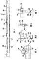
Fig. 1 is the stereogram of the stud of explanation one embodiment of the invention, and its split shed has a semicircle side;
Fig. 2 is the lateral view of stud shown in Figure 1;
Fig. 3 is the section along the 3-3 line of Fig. 2;
Fig. 4 is the detailed view shown in the circle 4 among Fig. 2;
Fig. 5 is the section along the 5-5 line of Fig. 2;
Fig. 6 is the section along the 6-6 line of Fig. 4;
Fig. 7 is the section along the 7-7 line of Fig. 2;
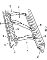
Fig. 8 is the stereogram of the another embodiment of the stud of explanation another embodiment of the present invention, and opening wherein is roughly quadrangle form;
Fig. 9 is the stereogram of the partial graph 8 looked from another angle;
Figure 10 is the lateral view of the stud of Fig. 8;
Figure 11 is the section along the 11-11 line of Figure 10;
Figure 12 is the stereogram of an embodiment again that is used to strengthen the stud of concrete slab;
Figure 13 is the lateral view of the stud of Figure 12;
Figure 14 is the section of the stud of Figure 13;
Figure 15 is the stereogram of stud that has some features of being similar to Fig. 1 and be similar to some features of Fig. 8;
Figure 16 is the stereogram of an embodiment again that is used to make the stud of combined member;
Figure 17 is the lateral view of the stud of Figure 16;
Figure 18 is the amplification profile along the 18-18 line of Figure 17;
Figure 19 is the stereogram of the combined member that is joined together to form by two studs of Figure 16;
Figure 20 is for using the stereogram of an embodiment again of round-meshed recess, and wherein circular hole penetrates described recess;
Figure 21 is the lateral view of the embodiment of Figure 20;
Figure 22 is the lateral view that is used for embedding the stud of concrete slab; And
Figure 23 is the end-view of the stud of Figure 22.
The specific embodiment
As mentioned above, the invention provides to have and reduce thermal conductivity and be applicable to the metal sheet stud that sets up various structures, wall, floor (floor), roof etc.Especially, the present invention also provides and is applicable to that extensive reinforcement is applied in the metal sheet stud of the thin shell concrete plate in the wall of completion.This thin shell structures also can form floor and roof etc.The present invention also provides by two studs are partly linked together combined member that forms and the method for making this combined member.
With reference to Fig. 1 as seen, its to show the present invention be form with the stud of being made by metal (being steel in this case) plate 10.Stud 10 has basic for the web 12 on plane with along the edge of a wing, edge 14 of each side formation of web 12.Each edge of a wing, edge is by forming with this web of right-angle bending.Antelabium 16 is formed on each edge of a wing, edge 14 with the right angle again.In web 12, opening 18 forms by the part metals plate is carried out punching.
In this embodiment, a side of opening 18 is formed with semicircle or the curved profile with Reference numeral 20 expressions.Be formed with the linear side profile of the prolongation of representing with Reference numeral 22 at the opposite side of opening 18.Short linear junction surface is arranged between curved profile 20 and linear side profile 22.Radiused corners for representing between this linear side profile and this junction surface with Reference numeral 24.The entire circumference of opening 18 is extended with the edge of a wing, edge 26 that meets at right angles and form with web 12.Linear side profile 22 along this opening is formed with support antelabium 28.Support antelabium 28 by part punching but still form along the part web 12 that this side of opening 18 keeps being connected with web 12.Support antelabium 28 and form with first right angle bends 30 perpendicular to this web plane, subsequently its with the plane parallel of web 12 but second right angle bends 32 separately form.
Like this, support antelabium 28 and form the short groove shape of extending along the linear side of opening 18.Like this, support antelabium 28 and greatly strengthened stud 10 along the linear side length of opening 18.
This feature allows opening 18 to form big relatively size, so that passing opening 18 for the pipeline of C shape is extensible shown in the sectional view and only be subjected to being horizontally through the restriction of lateral dimension of the opening of web 12.Compare with the stud with triangle open mouth, this is great improvement.In this leg-of-mutton opening, line size is subjected to the strictness restriction of the physical dimension of this opening; Perhaps selectively, it only can hold flexible circular air conditioning duct.
It should be noted that the shape of opening 18 and layout define the strut 34 that crosses web 12 diagonally extendings.This strut is longer than the strut that is limited in the stud with triangle open mouth, and longer thus.Because the heat of conduction only transmits along these struts, so owing to the actual heat waste that these struts caused is lacked than the stud with triangle open mouth.Stud 10 also is formed with recess 36 in the opposite end of each strut 34, locates this strut in this opposite end and outwards opens up in the web 12.The groove of going out 38 medially passes recess 36.Groove 38 has hindered the conduction of heat of crossing this stud effectively, and has improved its thermal efficiency.The heat of conduction will be had to the propagated of bending before the stud edge that arrives outer wall (not shown) place.The stud of this embodiment has superiority.It will and keep removing the peak discharge metal by die-cut openings in the high strength of the triangular duct on two edges of this stud and combine.The largest portion of reservation metal is also folded-out to form the supporting walls of this pipeline one side with it.Fig. 8 to Figure 11 has enumerated another embodiment of stud 40.This stud has the common feature of stud 10 of some and Fig. 1.For example, it has the web 42 and the edge of a wing, edge 44.
Yet the edge of a wing, edge 44 bends to outside the plane of this web with about miter angle based on the reason with explanation.This angle can change a little at various application.
In this case, stud 40 has the opening 46 that is roughly quadrangle form.
Crossing part in two adjacent inclined sides and short linear side 50 has the horn shape turning.The inclined side of two adjacent apertures 46 defines the strut 52 that between them side along slant path from web extends to opposite side.
In order to reduce heat transfer, the position adjacent place of respectively holding with each strut 52 in the edge of a wing, edge 44 forms a series of recesses 62, and same as in figure 1, forms groove 64 in this recess.
Many features of stud also are suitable for forming the stud that is used in the reinforcement thin shell concrete plated construction among Fig. 1 and/or Fig. 5.
This stud 70 is as Figure 12, Figure 13 and shown in Figure 14.
The edge of a wing, edge 74 that stud 70 has web 72 as shown in Figure 5 and tilts.Stud 70 has the opening 76 of quadrangle form as shown in Figure 5.
Have as shown in Figure 5 a series of gripper shoes 78 along a side of web 72.These gripper shoes 78 are with an angular bend.The free margins of these gripper shoes 78 is sandwiched in the groove 80 that is formed on the edge of a wing, edge 74, forms the pipeline of a series of fixed length thus.The edge of a wing, edge and gripper shoe all are formed with and are used to the linear grooves that makes intensity bigger.
On the relative side of web 72, have the edge of a wing, improved edge 82 and improved gripper shoe 84.The edge of a wing, edge 82 is outwardly-bent and be formed with a series of opening or holes 86 that concrete flows that are used for.
82 antelabium 88 that turn back that form are used to embed in the concrete along the edge of a wing, edge.The gripper shoe 84 that is formed by the integral part of the web 72 that strikes out opening 76 is to fold back with the angle of the edge of a wing, edge 82 complementations and to be discontinuous.Embedding antelabium 90 is formed on the gripper shoe 84 and is used to embed in the concrete.
Thus, this embodiment provides to strengthening the high strength stud that concrete slab is provided with.Be partially submerged in the concrete but the edge of a wing, edge 82 that is spaced laterally apart in this concrete slab and gripper shoe 84 will provide the safest adhesion between stud and the concrete.
The metal sheet that this stud can adopt thickness to reduce.What can expect is, can obtain at least one standard size or may two standard-sized minimizings when concrete slab enough supports still offering.
This will reduce the cost of this concrete slab.Because standard-sized minimizing has reduced the actual metal amount that heat-transfer path can be provided, so this also will reduce the heat transfer by concrete slab and stud.
Figure 15 shows the stud 100 of another kind of form, and this stud 100 also has the feature of further its intensity of increase, or on the contrary, and it is compared the material that can allow to use minimal thickness more and still can obtain identical or better intensity with previous stud.
Stud 100 have web 102 with along all identical edge of a wing, edge 104 of the either side of this web.The edge of a wing, edge 104 with the plane bending at angle of this web.Whole planomural 106 extends on the plane perpendicular to this web from the edge of a wing, edge 104.Supporting walls 108 integrally extends and curves inwardly with the angle with 104 complementations of the edge of a wing, edge from planomural 106.Supporting walls 108 ends at web 102 and contacts and lean against angled antelabium 110 on the web 102.Antelabium 110 is bent to L shaped and extends perpendicular to the plane of web 102.Opening 112 penetrates web 102 as previously mentioned and forms, and has the quadrangle form shown in the embodiment of Fig. 8, and has the foregoing edge or the edge of a wing 114 that forms around it.The linear side 116 of opening 112 and 118 flaps 120 by metal sheet limit, for will illustrative purposes, this linear side is 114 extensions integrally from the edge of a wing, to remain more by the metal that opening 112 cuts away thus and be applied to improve this stud, rather than it will be abandoned as waste material.Flap 120 self folds back to clamp the adjacent antelabium 110 on supporting walls 108.Like this, each side of this stud all is formed with and is used for high-intensity continuous triangle shape pipeline, and the free margins of each pipeline is all by clamping and fix from the rammed whole flap of opening compartment of terrain.More metal is retained in this stud, and it can be gained in strength or can allow in this alternative structure and reduce standard size, and can not increase heat waste by stud by any way.In the edge of a wing, edge 104 and supporting walls 108, form ridge, be used to add high strength.Can in this web, form the opening (not shown) of recess and fluting as mentioned above, with further minimizing heat waste.The stud of this form can have higher intensity than the stud among Fig. 5 under certain conditions.Yet, should see that it needs to adopt the web of broad at the very start.The supporting walls and the edge of a wing, edge and planomural (planar wall) integrally form.This means to need the strip material of broad so that beginning forms these walls with regard to having enough metals.Different is that this embodiment has kept from the die-cut a spot of a little metal of this opening, and some waste a little thus.
Figure 16, Figure 17, Figure 18 and Figure 19 show an embodiment again of stud.
This is the combining structure of being made by the stud 132 that two moulding independently of one another also link together subsequently 130 (Figure 19), provides high strength and light weight to give combined member 130.
In this embodiment, two studs 132 all form and have identical member.
Two studs can be formed by separating individual strip metal plate, perhaps can form individual strip material simply, be cut into two identical length subsequently with straight flange and zigzag limit.
Each stud 132 all has web 134.A side of this web is straight.It has as shown in figure 10 with the crooked at angle continuous edge of a wing, edge 136 of web 134.
Some metals along bottom sides 146 intactly stay and are folded to form folding groove 152, so that clamp the free margins of ridge wall 140 at certain intervals.Between these folding grooves 152, have and be formed on the recess 154 that moves in order to auxiliary restriction heat in web 134 and the ridge wall 140.
The side of the web 134 relative with the edge of a wing, edge 136 forms along the zigzag path that is limited with peak portion 156 and paddy portion 158.The edge of a wing, edge 160 that has continuous formation along this zigzag limit.
In use, these two studs 132 as shown in figure 19 and put, their peak portion 156 contacts and their paddy portion limit pass this member bigger and are roughly hexagonal opening simultaneously.Thus, large-diameter pipeline can optionally pass this member.Peak portion 156 is fixed to one another to form combined member by welding etc.
The stud of shop drawings 1 at first forms the opening 18 and the edge of a wing, edge 26 in suitable forcing press.This forcing press can be spiral moulding press (flying die press), but useful is, employing has two rotating mould backing rolls and the rotational pressure machine of the mould that is provided with on backing roll, in such rotational pressure machine, along with metal sheet moves between backing roll, two backing roll rotations are so that mould lumps together or separately.After forming the edge of a wing, edge, form recess 36 and go out groove 38 at die-cut formation opening, in around openings, use therein half-formed metal sheet subsequently by a series of such as known roller die seat that need not to illustrate itself.To sequentially form the axial bend 30 and 32 that forms in the edge of a wing, edge 14 and the edge of a wing, edge 14 on the opening either side at the roller die on the die holder.
In Fig. 8, Figure 13 and Figure 15, antelabium upset is to clamp this metal sheet, and this also is to finish in a series of roller dies that metal sheet passes through at a high speed, and antelabium is with efficient and economic mode moulding and along the axis bending of metal sheet.
Usually remain unchanged smooth and do not have the upstream of the rotational pressure machine of moulding to finish at band-like plate band-like plate is cut into fixed length.Like this, the every metal sheet that will experience various punching presses, moulding and rolling and forming order is cut into the desired precise length of finished product stud in advance.
This also can band-like plate be cut into fixed length, although may be difficult to control in the downstream of roller die.
What must remember is, when being cut into fixed length, must leave feed (provision) respectively holding of each stud, to stay astomous stud end, it can be in the appropriate location in final structure like this, and while all openings in each stud are crossed this structure and are in alignment with each other.This will make the fitting operation by this opening be very easy to.
The suitable control that does not form part of the present invention is bonded in the rotational pressure machine, so that this rotational pressure machine is regularly accurately operated the desired position of each stud.Each end at each stud does not require the position of opening and moulding, and this control is not worked this rotational pressure machine, so that the passing of guiding and traction metal sheet with respectively holding not punching press, not moulding.
Under the situation of embodiment shown in Figure 19, after forming two studs 132, their peak portion 156 is fixed together to form combining structure 130 by welding or any other suitable fastening means.
Figure 20 and Figure 21 have provided another embodiment.In this case, stud 170 is similar to the stud among Fig. 1, and it has the web 172 and the edge of a wing, edge 174.
The opening 176 that penetrates web 172 is the be roughly tetragonal shape similar to opening shown in Figure 10 46.Groove 178 forms with form same as in figure 1.
Recess 180 with center hole 182 is formed in the web 172 and the identical position of recess 36 among Fig. 1.But find the heat transfer of described this web of circular hole restricted passage.By forming circular hole with recess, these circular holes form just like the edge of a wing, edge shown in the figure, and they have increased the intensity of this stud thus.
This feature on the circular hole and the edge of a wing, edge can be used to replace other recesses that comprises Reference numeral 36,62 or 154 shown in the drawings.
Figure 22 and Figure 23 show the stud that is used for embedding concrete slab.
Stud 190 all is similar to the stud of Fig. 1 aspect most of, and has most of identical feature.Stud 190 can have semicircle main opening as shown in Figure 1 or can have as Figure 10 and trapezoidal main opening shown in Figure 20.
Stud 190 have as Figure 20 and embodiment illustrated in fig. 21 in circular hole 192.Yet in this case, the edge of a wing, an edge 194 is outwardly-bent to form the inclination edge of a wing 196.The inclination edge of a wing 196 be formed with similar opening 198, be used to groove that concrete is flow through.Bolt 200 is along the free margins bending on the inclination edge of a wing 196.
The inclination edge of a wing of this form that is used for embedding concrete is applicable to the stud of Fig. 1, the stud of Figure 10 or the stud of other variations.The front is the explanation in this preferred embodiment of the present invention that only provides by example.The present invention is not limited to described any concrete feature, but should be appreciated that its all changes all will fall within the scope of appended claims.
Claims (36)
1. a steel member is used in the braced structures, it is characterized in that comprising:
Web, it limits side and axis;
The edge of a wing, it is arranged at least one side;
Opening, it penetrates described web along described web at interval with certain space, and has preliminary dimension and profile;
One sidepiece of described at least web, it is connected with described web is whole from described opening cutting and maintenance, and described sidepiece is formed with at least two bends with respect to described web plane.
2. steel member as claimed in claim 1, described steel member comprises: recess, it is formed in the described web at interval with certain space; And groove, it is formed in the described recess.
3. steel member as claimed in claim 1, wherein said sidepiece define the groove shape of extending along the axis parallel with the axis of described web.
4. steel member as claimed in claim 1, wherein said opening has the shape that is limited by linear side and arc-shaped side edges, and the described sidepiece of described web and described linear side are one.
5. steel member as claimed in claim 1 wherein has two antelabium that form on the edge of a wing that each side of described web forms perpendicular to described web and along the described edge of a wing and perpendicular to the described edge of a wing respectively.
6. steel member as claimed in claim 1, wherein said opening are alternately arranged on orientation ground, and are limited the strut that diagonally extending crosses described steel member betwixt.
7. steel member as claimed in claim 6, wherein this steel member comprises groove, it is formed on the opposite end of each described strut in the described web.
8. steel member as claimed in claim 1, wherein said opening have toward each other and the parallel first longer linear side and the second shorter linear side.
9. steel member as claimed in claim 8, wherein this steel member is included in the inclined side of extending between the described linear side, limit a cardinal principle quadrangle form.
10. steel member as claimed in claim 9, wherein said opening are alternately arranged on orientation ground, and wherein be limited with the strut that described steel member is crossed in extension between described inclined side.
11. steel member as claimed in claim 9, wherein this steel member comprises groove, and it is formed on the two ends that are adjacent to each described strut in the described web.
12. steel member as claimed in claim 10, the wherein said edge of a wing form with described web at angle, and comprise from the described edge of a wing planomural that extends perpendicular to described web, the supporting walls that forms at described planomural and the antelabium that is bent to form groove shape along described supporting walls.
13. steel member as claimed in claim 12, wherein this steel member comprises sidepiece, it forms by the described web of part is whole, the described web of this part is from described opening cutting and outwardly-bent towards the described antelabium of described supporting walls, and the edge of described sidepiece is sandwiched in the described antelabium to form triangular shaped substantially pipeline.
14. steel member as claimed in claim 13, wherein this steel member comprises groove, and it forms along the described edge of a wing in described web.
15. steel member as claimed in claim 12, wherein from this opening cutting sidepiece but keep described sidepiece to be connected with described web integral body, described sidepiece on described web one side is with from the described web of described edge of a wing fork at angle, and form the embedding antelabium along described sidepiece, to be used for embedding concrete slab.
16. steel member as claimed in claim 15, wherein this steel member comprises that another embeds antelabium, and it is formed on the described edge of a wing on the described side of described web, in the described concrete slab of further embedding.
17. steel member as claimed in claim 10, the wherein said edge of a wing and described web are at angle, and comprise planomural that extends perpendicular to described web from the described edge of a wing and the supporting walls that extends from described planomural integral body.
18. steel member as claimed in claim 17, wherein said sidepiece and described supporting walls are bonded with each other, to limit the triangular shaped pipeline that is roughly along each side extension of described steel member.
19. steel member as claimed in claim 18, wherein said supporting walls is to extend from described planomural with the angle of described edge of a wing complementation, described thus supporting walls leans against on the described web in their edge, and the clamping antelabium is outwardly-bent and be sandwiched in the described sidepiece from described supporting walls.
20. steel member as claimed in claim 19, wherein longer along the described sidepiece of described longer linear side, and shorter along the described sidepiece of described shorter linear side, and wherein said supporting walls and the described antelabium on described supporting walls extend continuously along the axis that this web is parallel to this web.
21. steel member as claimed in claim 1, wherein said web define linear side, zigzag side and web axis;
The edge of a wing is positioned on this linear side.
22. steel member as claimed in claim 21, the wherein said edge of a wing is connected with planomural perpendicular to described web, and comprise with described planomural one, with the supporting walls of the angular bend of described edge of a wing complementation.
23. steel member as claimed in claim 22, wherein this steel member comprises the folding part that engages with described supporting walls.
24. steel member as claimed in claim 1, wherein said steel member is used for embedding concrete, and this steel member comprises: the inclination edge of a wing, and it is formed with and is used for the opening that concrete flows and passes; And bolt, it forms along the described inclination edge of a wing.
25. a combined member that is formed by two steel members as claimed in claim 21, wherein said two steel members are connected to each other to form combined member.
26. combined member as claimed in claim 25, the zigzag of wherein said steel member is edge limited peak portion and paddy portion, and wherein said two steel members connect at their peak portion place and fixed to one another at portion place, described peak, and the described paddy portion in described two steel members aligns mutually and limits the opening that penetrates described combined member.
27. a method that is used to make the steel member, wherein this steel member have web, side, along the edge of a wing that at least one described side forms and the opening that penetrates described web, it is characterized in that described method has following step:
Form described opening along described web at interval with certain space in described web, a side of described opening leaves the metal sidepiece that is connected with described web simultaneously;
Described at least one lateral edges along described web forms the edge of a wing, described edge; And
By be formed on the outer described sidepiece of described web plane at least along the desired shape or cross-section line twice crooked described sidepiece that is parallel to this web.
28. the method for manufacturing steel member as claimed in claim 27 is characterized in that described method also comprises the steps:
On the described edge of a wing, form planomural perpendicular to described web;
On described planomural, form the clamping antelabium; And
With described lateral curvature on described clamping antelabium.
29. the method for manufacturing steel member as claimed in claim 27 is characterized in that described method also comprises the steps:
Be formed on and extend the strut that crosses described web between the described opening; And
Each end that is adjacent to each strut in described web forms groove.
30. the method for manufacturing steel member as claimed in claim 27 is characterized in that described method also comprises the steps:
In described web, form be roughly quadrangle form, and limit the opening of longer linear side and shorter linear side; And the described sidepiece of described web keeps being connected with described web and integrally extending from first and second linear side.
31. the method for manufacturing steel member as claimed in claim 30 is characterized in that, described method also comprises the steps: to form two described sidepieces on the part on the adjacent edge of a wing.
32. the method for manufacturing steel member as claimed in claim 30 is characterized in that this method also comprises the steps:
Form and the described web described sidepiece of diverging from the described edge of a wing at angle; And
With the edge clamping of each sidepiece in the described edge of a wing of part.
33. the method for manufacturing steel member as claimed in claim 27, a lateral edges of wherein said web is linear, and other lateral edges is flexuose.
34. the method for manufacturing steel member as claimed in claim 33, wherein this method also comprises the steps:
Form described at least one edge of a wing, edge along described linear side edge;
Form the edge of a wing, edge along described zigzag edge; And
Penetrate described web and form opening.
35. the method for manufacturing steel member as claimed in claim 33, wherein this method also comprises the steps:
The sidepiece of the described web that the formation maintenance is connected with described web;
With described lateral curvature outside the plane of described web; And
On the described linear side of described web, make described sidepiece folding around the edge of a wing, the described edge of part.
36. the method for manufacturing steel member as claimed in claim 27, wherein said zigzag is edge limited peak portion and paddy portion, and described method also comprises the steps: two described steel members are linked together and their peak portion contacts with each other, to form combined member.
Applications Claiming Priority (2)
| Application Number | Priority Date | Filing Date | Title |
|---|---|---|---|
| CA002404320A CA2404320C (en) | 2002-09-30 | 2002-09-30 | Steel stud with openings and edge formations and method |
| PCT/CA2003/001628 WO2004038123A1 (en) | 2002-09-30 | 2003-10-27 | Steel stud with openings and edge formations and method for making such a steel stud |
Publications (2)
| Publication Number | Publication Date |
|---|---|
| CN1764765A CN1764765A (en) | 2006-04-26 |
| CN100447355C true CN100447355C (en) | 2008-12-31 |
Family
ID=29555392
Family Applications (1)
| Application Number | Title | Priority Date | Filing Date |
|---|---|---|---|
| CNB2003801102375A Expired - Fee Related CN100447355C (en) | 2002-09-30 | 2003-10-27 | Steel stud with opening and edge structure and its manufacturing method |
Country Status (9)
| Country | Link |
|---|---|
| US (1) | US20050229523A1 (en) |
| EP (1) | EP1740788A1 (en) |
| CN (1) | CN100447355C (en) |
| AR (1) | AR041989A4 (en) |
| AU (1) | AU2003280238A1 (en) |
| CA (1) | CA2404320C (en) |
| MY (1) | MY136099A (en) |
| SG (1) | SG106160A1 (en) |
| WO (1) | WO2004038123A1 (en) |
Families Citing this family (17)
| Publication number | Priority date | Publication date | Assignee | Title |
|---|---|---|---|---|
| AUPQ052199A0 (en) * | 1999-05-21 | 1999-06-17 | Wiltin Pty Ltd | Joining arrangements for structural members |
| US7587877B2 (en) | 2003-10-28 | 2009-09-15 | Best Joist Inc | Cold-formed steel joists |
| US20060150548A1 (en) * | 2004-12-27 | 2006-07-13 | Gcg Holdings Ltd | Floor system with stell joists having openings with edge reinforcements and method |
| EP1712697A3 (en) * | 2005-04-14 | 2007-12-05 | Zurecon Ag | Mounting profile |
| PL1961887T3 (en) * | 2007-02-23 | 2012-01-31 | Arcelormittal Commercial Sections S A | Method of manufacturing a structural beam with openings |
| US8490362B2 (en) * | 2007-04-05 | 2013-07-23 | The Boeing Company | Methods and systems for composite structural truss |
| CA2668945A1 (en) * | 2009-05-13 | 2010-11-13 | Ernest R. Bodnar | Open web stud with low thermal conductivity and screw receiving grooves |
| RU2487220C2 (en) * | 2009-05-18 | 2013-07-10 | Эрнест Р. Боднар | Open frame stand with low heat conductivity and seats for screws |
| US8061099B2 (en) | 2009-05-19 | 2011-11-22 | Tsf Systems, Llc | Vertical deflection extension end member |
| US8381469B2 (en) | 2010-04-08 | 2013-02-26 | Dizenio, Inc. | Cold formed joist |
| US8943776B2 (en) | 2012-09-28 | 2015-02-03 | Ispan Systems Lp | Composite steel joist |
| USD735895S1 (en) * | 2013-10-09 | 2015-08-04 | Dennis Edmondson | Structural insulating stud |
| US9790686B1 (en) | 2016-08-10 | 2017-10-17 | United States Gypsum Company | Triangular stud shaft wall system |
| MX2020001798A (en) | 2017-08-14 | 2020-09-25 | Varied length metal studs. | |
| CA3050000A1 (en) | 2019-07-16 | 2021-01-16 | Invent To Build Inc. | Concrete fillable steel joist |
| USD1021151S1 (en) | 2021-04-26 | 2024-04-02 | Jaimes Industries, Inc. | Framing member |
| CN116551335B (en) * | 2023-07-07 | 2023-10-03 | 成都飞机工业(集团)有限责任公司 | L-shaped part machining method and L-shaped part |
Citations (5)
| Publication number | Priority date | Publication date | Assignee | Title |
|---|---|---|---|---|
| DE2046459A1 (en) * | 1970-09-21 | 1972-04-13 | Haushalter, Dietmar, 5804 Herdecke | Beams for formwork, falsework and the like |
| US5527625A (en) * | 1992-09-02 | 1996-06-18 | Bodnar; Ernest R. | Roll formed metal member with reinforcement indentations |
| US5809724A (en) * | 1991-06-03 | 1998-09-22 | Rotary Press Systems Inc. | Construction panel and method of constructing a level portion of a building |
| US6170217B1 (en) * | 1999-02-05 | 2001-01-09 | Darrell G. Meyer | Bearing elements and methods relating to same |
| WO2003008732A1 (en) * | 2001-07-18 | 2003-01-30 | Ernest Bodnar | Steel stud and composite construction panel |
Family Cites Families (15)
| Publication number | Priority date | Publication date | Assignee | Title |
|---|---|---|---|---|
| US1502873A (en) * | 1924-07-29 | Perforated sheet metal | ||
| US1656871A (en) * | 1926-02-27 | 1928-01-17 | Goodyear Zeppelin Corp | Hollow girder |
| US1994716A (en) * | 1932-05-12 | 1935-03-19 | Goodyear Zeppelin Corp | Girder |
| US2088781A (en) * | 1936-01-29 | 1937-08-03 | W R Ames Company | Studding structure |
| US2092472A (en) * | 1936-12-04 | 1937-09-07 | Rafter Machine Company | Stud and rafter |
| US2177277A (en) * | 1937-06-02 | 1939-10-24 | Pacific Portland Cement Compan | Metal stud |
| US2185384A (en) * | 1938-04-20 | 1940-01-02 | Rafter Machine Company | Structural member |
| US2423682A (en) * | 1944-05-30 | 1947-07-08 | Douglas Aircraft Co Inc | Sheet metal structure |
| US4016688A (en) * | 1975-05-27 | 1977-04-12 | Fmc Corporation | Extensible crane boom structure |
| US4793113A (en) * | 1986-09-18 | 1988-12-27 | Bodnar Ernest R | Wall system and metal stud therefor |
| DE3720611A1 (en) * | 1987-06-23 | 1989-01-05 | Mabey Hire Co | Steel girder |
| JPH03129031A (en) * | 1989-05-08 | 1991-06-03 | Uniframes Ltd | Metal floor beam |
| US5207045A (en) | 1991-06-03 | 1993-05-04 | Bodnar Ernest R | Sheet metal structural member, construction panel and method of construction |
| US5592848A (en) | 1991-06-03 | 1997-01-14 | Bodnar; Ernest R. | Method of simultaneously forming a pair of sheet metal structural members |
| CA2399825A1 (en) * | 1999-02-08 | 2000-08-17 | Rocheway Pty. Ltd. | A structural member |
-
2002
- 2002-09-30 CA CA002404320A patent/CA2404320C/en not_active Expired - Lifetime
-
2003
- 2003-10-27 US US10/510,351 patent/US20050229523A1/en not_active Abandoned
- 2003-10-27 AU AU2003280238A patent/AU2003280238A1/en not_active Abandoned
- 2003-10-27 AR ARM030103921U patent/AR041989A4/en active IP Right Grant
- 2003-10-27 CN CNB2003801102375A patent/CN100447355C/en not_active Expired - Fee Related
- 2003-10-27 WO PCT/CA2003/001628 patent/WO2004038123A1/en not_active Application Discontinuation
- 2003-10-27 EP EP03770807A patent/EP1740788A1/en not_active Withdrawn
- 2003-10-27 MY MYPI20034078A patent/MY136099A/en unknown
- 2003-10-28 SG SG200306393A patent/SG106160A1/en unknown
Patent Citations (5)
| Publication number | Priority date | Publication date | Assignee | Title |
|---|---|---|---|---|
| DE2046459A1 (en) * | 1970-09-21 | 1972-04-13 | Haushalter, Dietmar, 5804 Herdecke | Beams for formwork, falsework and the like |
| US5809724A (en) * | 1991-06-03 | 1998-09-22 | Rotary Press Systems Inc. | Construction panel and method of constructing a level portion of a building |
| US5527625A (en) * | 1992-09-02 | 1996-06-18 | Bodnar; Ernest R. | Roll formed metal member with reinforcement indentations |
| US6170217B1 (en) * | 1999-02-05 | 2001-01-09 | Darrell G. Meyer | Bearing elements and methods relating to same |
| WO2003008732A1 (en) * | 2001-07-18 | 2003-01-30 | Ernest Bodnar | Steel stud and composite construction panel |
Also Published As
| Publication number | Publication date |
|---|---|
| WO2004038123A1 (en) | 2004-05-06 |
| CN1764765A (en) | 2006-04-26 |
| SG106160A1 (en) | 2004-09-30 |
| AU2003280238A1 (en) | 2004-05-13 |
| MY136099A (en) | 2008-08-29 |
| CA2404320C (en) | 2005-02-08 |
| EP1740788A1 (en) | 2007-01-10 |
| CA2404320A1 (en) | 2003-11-18 |
| AR041989A4 (en) | 2005-06-08 |
| US20050229523A1 (en) | 2005-10-20 |
Similar Documents
| Publication | Publication Date | Title |
|---|---|---|
| CN100447355C (en) | Steel stud with opening and edge structure and its manufacturing method | |
| US8359813B2 (en) | Steel stud with openings and edge formations and method | |
| CN100419184C (en) | Floor system with steel joists having openings with edge reinforcements and producing method | |
| JP4563384B2 (en) | Improved beam | |
| US7231746B2 (en) | Sheet metal stud and composite construction panel and method | |
| US4005942A (en) | Metal hanger | |
| US3043408A (en) | Metallic framing element | |
| US6250886B1 (en) | Axial flow fan and fan blade | |
| US7448178B2 (en) | Field fabricated joist hanger | |
| JP2002522665A (en) | Metal sheet piling | |
| US8226051B2 (en) | Pipe locator and support | |
| US5727762A (en) | Riser clamp and method of fabricating same | |
| US20130202344A1 (en) | Expansion Joint Bracket | |
| EP1760212A2 (en) | Skewed girder tie | |
| CN102753766A (en) | Thin-walled, cold-formed lightweight structural profile element and method for producing such a profile element | |
| US6301857B1 (en) | Composite structural member | |
| JP2003531987A (en) | Composite structural members | |
| US5529092A (en) | Air duct turning vane and rail assembly | |
| EP1702710A1 (en) | Tube producing method, heat exchanging tube produced by the method, and heat exchanger using the tube | |
| US20020067950A1 (en) | HVAC flange and flange machine | |
| US20070272342A1 (en) | Structural Beam With Openings | |
| US9021759B2 (en) | Serpentine insert for open web grid | |
| JP4380516B2 (en) | Aluminum truss structure | |
| US537036A (en) | George hayes | |
| JP4812491B2 (en) | Aluminum truss structure |
Legal Events
| Date | Code | Title | Description |
|---|---|---|---|
| C06 | Publication | ||
| PB01 | Publication | ||
| C10 | Entry into substantive examination | ||
| SE01 | Entry into force of request for substantive examination | ||
| C14 | Grant of patent or utility model | ||
| GR01 | Patent grant | ||
| C17 | Cessation of patent right | ||
| CF01 | Termination of patent right due to non-payment of annual fee |
Granted publication date: 20081231 Termination date: 20131027 |