CN100443752C - Linear guide device - Google Patents
Linear guide device Download PDFInfo
- Publication number
- CN100443752C CN100443752C CNB2004800355022A CN200480035502A CN100443752C CN 100443752 C CN100443752 C CN 100443752C CN B2004800355022 A CNB2004800355022 A CN B2004800355022A CN 200480035502 A CN200480035502 A CN 200480035502A CN 100443752 C CN100443752 C CN 100443752C
- Authority
- CN
- China
- Prior art keywords
- rolling element
- mentioned
- road
- hole
- linear guide
- Prior art date
- Legal status (The legal status is an assumption and is not a legal conclusion. Google has not performed a legal analysis and makes no representation as to the accuracy of the status listed.)
- Active
Links
Images


Abstract
A linear guide device has a guide rail (12), a slider body (15), an end cap (16), a large number of rolling bodies (18), and separators (22). The slider body (15) has a slider side rolling body raceway surface opposed to a rail side rolling body raceway surface (13) formed on the guide rail (12). The end cap (16) has a rolling body direction switching path (21) communicating with a rolling body load rolling path (19) formed between both rolling body raceway surfaces of the guide rail (12) and the slider body (15) and also communicating with a rolling body return path (20) formed in a penetrating manner in the slider body (15), along the longitudinal direction of the guide rail (12). In conjunction with relative linear movement of a slider (14) constituted of the slider body (15) and the end cap (16), the rolling bodies (18) roll in the rolling body load rolling path (19), the rolling body return path (20), and a rolling body direction switching path (21). The separators (22) are arranged between every two adjacent rolling bodies (18). The end cap (16) has a through hole (25) for assembling the rolling bodies (18) and the separators (22) from the outside of the slider (14) into the rolling body return path (19) and also has a cap member (26) removably fitted in the through hole (25). The cap member (26) forms part of the rolling body direction switching path (21).
Description
Technical field
The present invention relates to linear guide apparatus, particularly the linear guide apparatus that in the industrial machinery of work mechanism etc., uses as the device that worktable isoline moving body is guided on its movement direction.
Background technique
The linear guide apparatus that uses in the various industrial machineries such as work mechanism generally constitutes shown in Figure 63~65, has guide rail 12, slider body 15 and two end caps 16.
Slide block side roll track body face 17 is relative with rail-sides rolling element plane of trajectory orbital 13 respectively, between rail-sides rolling element plane of trajectory orbital 13 and the slide block side roll track body face 17, shown in Figure 65, be formed be used to rolling element load rolling road 19 that rolling element 18 is rolled on the length direction of guide rail 2.
Be formed with the rolling element that is used to make along with the linear relative movement of slide block 14 in rolling element load rolling road 19 rolling element 18 that rolls to return in the slider body 15 and return road 20 (with reference to Figure 65).This rolling element returns road 20 and is formed in the slider body 15 along the length direction of guide rail 12, is formed with rolling element load rolling road 19 and rolling element to return the rolling element direction conversion road 21 (with reference to Figure 65) that road 20 is communicated with in each end cap 16 that constitutes slide block 14 with slider body 15.
Rolling element direction conversion road 21 bends to roughly U word shape, therefore, returns rolling element 18 conversion direction on rolling element direction conversion road 21 that rolls in the road 20 on rolling element load rolling road 19 and rolling element respectively.
Assemble under the situation of such linear guide apparatus, in the past, shown in Figure 66, on the interim axle 23 of simulation guide rail, load onto slide block 14, pack rolling element 18 and separation member into and assemble linear guide apparatus in the slide block 14 in the end that never is contained in the slide block 14 on the interim axle 23.
But, in such method, owing to be operation in narrow space when packing into rolling element 18 and separation member 22 in the slide block 14, so need plenty of time and operation in the linear guide apparatus assembling.In addition, owing to must the limit with the limit, position of packing into of mirror affirmation rolling element 18 and separation member 22 rolling element 18 and separation member 22 be packed in the slide block 14, so, need plenty of time and operation in the assembling operation of rolling element 18 and separation member 22.In addition, when rolling element 18 and separation member 22 were packed in the slide block 14, separation member 22 also can be in slide block 14 instead.
Summary of the invention
The present invention is in view of the above problems and research and development, and its purpose is to provide a kind of can be easily packs rolling element and separation member in the slide block into, realizes the linear guide apparatus of the raising of assembling performance.
For realizing this purpose, in the linear guide apparatus of the present invention, be provided with: guide rail; Slider body, it has with length direction along above-mentioned guide rail and is formed on the relative rolling element plane of trajectory orbital of rolling element plane of trajectory orbital on the above-mentioned guide rail; End cap, its have with the two rolling element plane of trajectory orbital that are formed on above-mentioned guide rail and slider body between rolling element load rolling road be communicated with and run through the rolling element that is arranged in the above-mentioned slider body and return the rolling element direction conversion road that the road is communicated with length direction along above-mentioned guide rail; A plurality of rolling elements, it is followed the linear relative movement of the slide block that is made of above-mentioned slider body and above-mentioned end cap and returns at above-mentioned rolling element load rolling road, rolling element and to roll in road and the rolling element direction conversion road; A plurality of separation members, it is located in above-mentioned a plurality of rolling element between adjacent two rolling elements.Above-mentioned end cap has and is used for above-mentioned rolling element and the above-mentioned separation member above-mentioned rolling element of packing into from the outside of above-mentioned slide block is returned through hole in the road.
In the above-mentioned linear guide apparatus of the present invention, end cap preferably has the cover of inaccessible above-mentioned through hole.In this case, cover is preferably chimeric and form the part on above-mentioned rolling element direction conversion road with above-mentioned through hole.
Above-mentioned linear guide apparatus of the present invention is fit to employing as rolling element and forms roller shape or spherical.In this case, separation member preferably has the rolling element surface of contact of the concavity that contacts with above-mentioned rolling element.In addition, separation member preferably comprises the main part that is positioned between above-mentioned two rolling elements and is configured in the arm of pairing left and right of the both sides of this main part.In addition, through hole preferably has the guiding groove that can engage with the arm of above-mentioned separation member with being free to slide, and rolling element returns the road and above-mentioned rolling element direction conversion road preferably has the guiding groove that can engage with the arm of above-mentioned separation member with being free to slide.
In the linear guide apparatus of the present invention, separation member can connect to row by the binding parts with flexual band shape.In addition, preferably to return the road relative and be formed on the above-mentioned end cap with above-mentioned rolling element for linear guide apparatus of the present invention, through hole.In addition, through hole preferably is formed on the above-mentioned end cap coaxially with prolonging the elongation line that above-mentioned rolling element returns the center line on road, but also can with prolong elongation line that above-mentioned rolling element returns the center line on road and intersect and be formed on the above-mentioned end cap.
In the linear guide apparatus of the present invention, through hole preferably is formed on the above-mentioned end cap with the big opening area of opening area that returns the road than above-mentioned rolling element, but also can be formed on the above-mentioned end cap to return the roughly the same opening area of the opening area on road with above-mentioned rolling element.
In the linear guide apparatus of the present invention, through hole can form and comprise the shape of a part that above-mentioned rolling element returns the section shape on road.In addition, end cap preferably has the positioning part that above-mentioned cover is positioned.In this case, cover preferably has the engagement portion that engages with above-mentioned positioning part.
In the linear guide apparatus of the present invention, rolling element and separation member preferably with have with the side of above-mentioned rolling element or above-mentioned arm respectively the rolling element of two opposite inner walls face insert in anchor clamps pack above-mentioned slide block into from above-mentioned through hole.In this case, rolling element inserts anchor clamps and is preferably formed the shape chimeric with above-mentioned through hole.Further, the front end that end cap preferably has with above-mentioned rolling element inserts anchor clamps engage and has a positioning part that above-mentioned rolling element insertion anchor clamps is positioned and above-mentioned cover is positioned.
Description of drawings
Fig. 1 is the front elevation of the linear guide apparatus of first mode of execution of the present invention;
Fig. 2 is the figure of the II-II section of presentation graphs 1;
Fig. 3 is the explanatory drawing of effect that is used to illustrate the linear guide apparatus of first mode of execution;
Fig. 4 is expression from the through hole of being located at end cap rolling element and separation member are packed into the figure of an example of the situation in the slide block;
Fig. 5 is used to illustrate with rolling element and separation member from pack into the explanatory drawing of problem points of the situation in the slide block of the straight section on rolling element circulation road;
Fig. 6 is from pack into the explanatory drawing of advantage of the situation in the slide block of the straight section on rolling element circulation road with rolling element and separation member;
Fig. 7 is the front elevation of the linear guide apparatus of second mode of execution of the present invention;
Fig. 8 is the figure of the XIII-XIII section of presentation graphs 7;
Fig. 9 is the stereogram of the linear guide apparatus of the 3rd mode of execution of the present invention;
Figure 10 is the front elevation that is shown in the linear guide apparatus of Fig. 9;
Figure 11 is the figure of the XI-XI section of expression Figure 10;
Figure 12 is the figure of the XII-XII section of expression Figure 11;
Figure 13 is the profile that is shown in the separation member of Figure 11;
Figure 14 is the planimetric map that is shown in the separation member of Figure 13;
Figure 15 is the front elevation that is shown in the separation member of Figure 14;
Figure 16 is the front elevation that is shown in the end cap of Fig. 9;
Figure 17 is the front elevation of the XVII-XVII section of expression Figure 16;
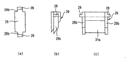
Figure 18 is the figure that the direction conversion road of expression Figure 11 forms parts, is that front elevation, (b) are that planimetric map, (c) are the A-A sectional drawings of (b) (a);
Figure 19 is the stereogram that the expression rolling element inserts an example of anchor clamps;
Figure 20 is used to illustrate that the rolling element that uses Figure 19 inserts anchor clamps and with pack into the explanatory drawing of assembling method of the situation in the slide block of rolling element and separation member;
Figure 21 is the stereogram of the linear guide apparatus of the 4th mode of execution of the present invention;
Figure 22 is the front elevation that is shown in the linear guide apparatus of Figure 21;
Figure 23 is the XXIII-XXIII sectional drawing of Figure 22;
Figure 24 is the figure that the expression rolling element inserts an example of anchor clamps;
Figure 25 is the figure of the jig main body of expression Figure 24, is that the planimetric map of jig main body, front elevation, (c) that (b) is jig main body are the profiles of jig main body (a);
Figure 26 is the figure of the lid of expression Figure 24, is that the planimetric map of lid, front elevation, (c) that (b) is lid are the profiles of lid (a);
Figure 27 is the stereogram of the linear guide apparatus of the 5th mode of execution of the present invention;
Figure 28 is the front elevation that is shown in the linear guide apparatus of Figure 27;
Figure 29 is the XXIX-XXIX sectional drawing of Figure 27;
Figure 30 is the figure that the expression rolling element inserts an example of anchor clamps;
Figure 31 is the figure of the jig main body of expression Figure 30, is that the planimetric map of jig main body, front elevation, (c) that (b) is jig main body are the profiles of jig main body (a);
Figure 32 is the figure of the lid of expression Figure 30, is that the planimetric map of lid, front elevation, (c) that (b) is lid are the profiles of lid (a);
Figure 33 is the stereogram of the linear guide apparatus of the 6th mode of execution of the present invention;
Figure 34 is the front elevation that is shown in the slider body of Figure 33;
Figure 35 is the front elevation that is shown in the end cap of Figure 33;
Figure 36 is the B-B sectional drawing of Figure 35;
Figure 37 is the profile of separation member;
Figure 38 is the figure of the cover of the dismantled and assembled through hole that is entrenched in end cap freely of expression;
Figure 39 is the stereogram that the rolling element that uses when being loaded into rolling element and separation member in the slide block of linear guide apparatus among Figure 33 inserts anchor clamps;
Figure 40 is the front elevation that is shown in the linear guide apparatus of Figure 33;
Figure 41 is used to illustrate the explanatory drawing that uses rolling element shown in Figure 39 to insert anchor clamps and rolling element and separation member are loaded into the method in the slide block;
Figure 42 is used to illustrate the explanatory drawing that uses rolling element shown in Figure 39 to insert anchor clamps and rolling element and separation member are loaded into the method in the slide block;
Figure 43 is used to illustrate the explanatory drawing that uses rolling element shown in Figure 39 to insert anchor clamps and rolling element and separation member are loaded into the method in the slide block;
Figure 44 is the figure of variation that is shown in the through hole of Figure 36;
Figure 45 is the figure of variation that is shown in the through hole of Figure 44;
Figure 46 is the figure of variation that is shown in the positioning part of Figure 36;
Figure 47 is the figure of structure of the cover of the expression through hole that is entrenched in Figure 46;
Figure 48 is the figure that is shown in the variation of Figure 36 through hole;
Figure 49 is the figure of cover of the through hole of the inaccessible Figure 48 of expression;
Figure 50 is the figure of major component of the linear guide apparatus of expression the 7th mode of execution of the present invention;
Figure 51 is the figure of cover of the through hole of the inaccessible Figure 50 of expression;
Figure 52 is the figure that through hole that expression is formed on end cap does not have the variation of the through hole under the situation of guiding groove;
Figure 53 is the figure that through hole that expression is formed on end cap does not have the variation of the through hole under the situation of guiding groove;
Figure 54 is the figure of expression with the embodiment under the situation of the oblique chamfer machining in bight of through hole;
Figure 55 is the figure of expression with the embodiment under the situation of the circular-arc chamfer machining in bight of through hole;
Figure 56 is the figure of the bond length of expression through hole than the embodiment under the big situation of rolling element diameter;
Figure 57 is the figure of the long edge lengths of expression through hole than the embodiment under the big situation of the size between the arm of separation member;
Figure 58 is the figure of the long edge lengths of the bond length of expression through hole and through hole bigger than the diameter of rolling element than the embodiment under the big situation of the axial length of rolling element;
Figure 59 is the figure that the expression rolling element forms the embodiment under the spherical situation;
Figure 60 is the figure that the expression rolling element forms the embodiment of the through hole under the spherical situation;
Figure 61 is the front elevation of cover that is entrenched in the through hole of Figure 60;
Figure 62 is the figure of structure that is shown in the cover of Figure 61;
Figure 63 is the stereogram of existing linear guide apparatus;
Figure 64 is the front elevation that is shown in the linear guide apparatus of Figure 63;
Figure 65 is the C-C sectional drawing of Figure 64;
Figure 66 is used to illustrate the explanatory drawing of method of rolling element and separation member of packing in the slide block that is shown in Figure 63.
Embodiment
Following with reference to Fig. 1~6 explanations, first mode of execution of the present invention, wherein, to using same-sign with the identical or suitable part shown in Figure 63~65, the detailed content of this part is omitted explanation.
Among Fig. 1, the linear guide apparatus of first mode of execution of the present invention has guide rail 2, slider body 15 and two end caps 16.On the end cap 16, as shown in Figure 2, the through hole 25 of be formed for will in rolling element returns road 20, packing into rolling element 18 and separation member 22 from the outside of slide block 14, to return road 20 relative with rolling element.These through hole 25 its sections vertical with the direction of packing into of rolling element 18 and separation member 22 form rectangle, are formed on the end cap 16 with the big opening area of opening area that returns road 20 than rolling element.
In such structure, if cover 26 is taken out from end cap 16, then rolling element returns road 20 and forms opened state by through hole 25, so as shown in Figure 3, can pack into the rolling element of slider body 15 of rolling element 18 and separation member 22 be returned in the road 20 from the through hole 25 of being located at end cap 16.Therefore, even do not use during the assembling of linear guide apparatus the interim axle 23 of Figure 65 rolling element 18 and separation member 22 easily can be seated in the slide block 14, so can improve the assembling performance of linear guide apparatus yet.In addition, do not need yet, confirm the position of packing into of rolling element 18 and separation member 22 by mirror as foregoing existing example.
And then, because in can packing rolling element 18 and separation member 22 into slide block 14 from the end cap side, so as shown in Figure 4, but the also automation of operation of packing into of rolling element 18 and separation member 22.
In addition, in the first above-mentioned mode of execution, by being used for that rolling element 18 and separation member 22 through holes 25 that rolling element returns in the road 20 of packing into are returned the road 20 relative end caps 16 of being located at rolling element, thereby in the time of in slide block 14 that rolling element 18 and separation member 22 are packed into, as shown in Figure 3, the curved section on rolling element direction conversion road 21 is big open mode.Thus, in the time of can preventing that last remaining rolling element 18 from packing between the separation member 22, the bight 22a (with reference to Fig. 5) of separation member 22 is by rolling element 18 damages.That is, when the loading port of rolling element and separation member was formed on the straight section on rolling element circulation road, as shown in Figure 6, when last remaining rolling element 18 was packed between the separation member 22, the bight 22a of separation member 22 may be damaged by rolling element 18.To this, in first mode of execution, when rolling element 18 and separation member 22 are packed in the slide block 14, the curved part on rolling element direction conversion road 21 is divided into big open mode, thus, and as shown in Figure 5, it is big that the interval of two adjacent separation members 22 becomes, so in the time of can preventing that last remaining rolling element 18 from packing between the separation member 22, the bight 22a of separation member 22 is damaged by rolling element 18.
In addition, even under the situation in the slit that dwindles rolling element row, when packing rolling element into last, situations such as rolling element 22 damages can not appear yet, so separation member 22 can have the function that prevents that rolling element from coming off.
In the first above-mentioned mode of execution, be used for rolling element 18 and separation member 22 rolling element of packing into is returned through hole 25 and rolling element in the road 20 to return road 20 relative and be formed on end cap 16, but shown in second mode of execution shown in Fig. 7 and 8, being used for packing rolling element 18 and separation member 22 into through hole 25 that rolling element returns in the road 20 also can to return the part on road 20 relative and be arranged on end cap 16 with rolling element.That is, through hole 25 forms and comprises the shape of a part that rolling element returns the section shape on road 20.
Below with reference to Fig. 9~20 explanations the 3rd mode of execution of the present invention.
Among Fig. 9, the linear guide apparatus of the 3rd mode of execution of the present invention has guide rail 12, slider body 15, end cap 16 and side seal portion 24.
Slide block side roll track body face 17 is relative with rail-sides rolling element plane of trajectory orbital 13 respectively, between rail-sides rolling element plane of trajectory orbital 13 and the slide block side roll track body face 17, as shown in figure 11, be formed for making the rolling element load rolling road 19 of rolling element 18 in the length direction rolling of guide rail 2.
In slider body 15, the rolling element that is used to make along with the linear relative movement of slide block 14 in rolling element load rolling road 19 rolling element 18 that rolls to return returns road 20 (with reference to Figure 11) and forms along the length direction of guide rail 12.This rolling element returns road 20 and so forms, that is, be located on the slider body 15 at the through hole 31 (with reference to Figure 10) that connects on the length direction of guide rail 2, and above-mentioned through hole 31 embeds resinous cylinder 32.
In slide block 15 constitutes each end cap 16 of slide block 14, form with rolling element load rolling road 19 and rolling element and return the rolling element direction conversion road 21 (with reference to Figure 11) that road 20 is communicated with.This rolling element direction conversion road 21 bends to roughly U font, and therefore, rolling element load rolling road 19 and rolling element return the rolling element 18 that rolls respectively in the road 20 and change at rolling element direction conversion road 21 travel directions.
Rolling element 18 forms cylindric, is installed in the separation member 22 (with reference to Figure 11) of 18 of each rolling elements, is the vibration that suppresses to be caused by the mutual impact of rotor and the rising of noise level, and is formed by the material softer than rolling element 18 materials (for example resin).
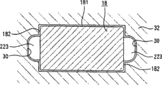
Rolling element 18 has the rolling surface cylindraceous 181 (with reference to Figure 12) that rolls on rail-sides rolling element plane of trajectory orbital 13 and slide block side roll track body face 17, the rolling element surface of contact 221,222 (with reference to Figure 13) of the concavity that joins with above-mentioned rolling surface 181 slips is set on the separation member 22.Separation member 22 shown in Figure 14 and 15, is made of the main part 224 that is positioned at 18 of two rolling elements and the arm 223 of pairing left and right of being located at the both sides of this main part 224.
Rolling element 18 and separation member 22 are kept by the retainer 29 (with reference to Figure 10) of 15 of guide rail 12 and slider bodies.
Rolling element 18 has circular end face 182 (with reference to Figure 12) in the two side ends of above-mentioned rolling surface 181, returns at the rolling element relative with these end faces 182 on the internal face on road 20 and rolling element direction conversion road 21 and forms the guiding groove 30 (with reference to Figure 12) that can engage with the arm 223 of separation member 22 with being free to slide.
Be provided on the end cap 16 pack into the rolling element of slider body 15 of rolling element 18 and separation member 22 is returned through hole 25 (with reference to Figure 16) in the road 20.It is relative and be formed on the end cap 16 that this through hole 25 and rolling element return road 20.In addition, through hole 25 is formed on the end cap 16 with the big opening area of opening area that returns road 20 than rolling element, by cover 26 (with reference to Figure 11) obturation that is arranged on the end cap 16.Be entrenched on the through hole 25 these cover 26 detachables, constitute the part on the rolling element direction conversion road 20 that forms in the end cap 16.
Through hole 25 has the step portion 27 (with reference to Figure 17) as the positioning part that cover 26 is positioned.This step portion 27 is formed in the end cap 16, and the engagement portion 28 (with reference to Figure 11) that engages with above-mentioned step portion 27 is set on the cover 26.
The rolling element that through hole 25 on being arranged on end cap 16 uses when being seated in rolling element 18 and separation member 22 in the slide block 14 inserts one of anchor clamps and is illustrated in Figure 19.Rolling element insertion anchor clamps 33 are combined into rectangular by four tabular bodys 34 and form.In addition, rolling element insertion anchor clamps 33 have end face 182 (with reference to Figure 12) the difference two opposite inner walls face 331 with rolling element 18, on these internal faces 331, the length direction that inserts anchor clamps 33 along rolling element is provided with the guiding groove 332 that can engage with the arm 223 of separation member 22 respectively with being free to slide.And then rolling element inserts anchor clamps 33 and forms the shape chimeric with through hole 25, and its front end forms the snap-latch surface 334 that engages with the step portion 27 of through hole 25.
In such rolling element inserts anchor clamps 33, load under the situation of rolling element 18 and separation member 22, the front end that inserts anchor clamps 33 with rolling inserts through hole 25 and inserts the snap-latch surface 334 of anchor clamps 33 and step portion 27 butts of through hole 25 until rolling element, afterwards rolling element 18 and separation member 22 are seated in the rolling element insertion anchor clamps 33, can prevent that then rolling element 18 and separation member 22 break away from from the front opening that rolling element inserts anchor clamps 33.
Have in the 3rd mode of execution of the present invention of this spline structure, to be used for rolling element 18 and separation member 22 through holes 25 that the rolling element of slider body 15 returns in the road 20 of packing into are arranged on end cap 16, thereby in linear guide apparatus when assembling, can be easily pack rolling element 18 and separation member 22 in the slide block 14 into, so can improve the assembling performance of linear guide apparatus.In addition, owing to use such rolling element shown in Figure 19 to insert anchor clamps 33 rolling element 18 and separation member 22 are packed in the slide block 14, so can prevent the overturning of separation member 22 in slide block 14.And then, by being used in rolling element 18 and separation member 22 through holes 25 that the rolling element of slider body 15 returns in the road 20 of packing into are returned road 20 relative being arranged on the end cap 16 with rolling element, and do not need big strength just rolling element 18 and separation member 22 can be packed in the slide block 14.
Below with reference to Figure 21~26 explanations the 4th mode of execution of the present invention.
Among Figure 21, the linear guide apparatus of the 4th mode of execution has guide rail 12, slider body 15 and end cap 16.
Slide block side roll track body face 17 is relative with rail-sides rolling element plane of trajectory orbital 13 respectively, between rail-sides rolling element plane of trajectory orbital 13 and the slide block side roll track body face, be formed for making rolling element 18 rolling element load rolling road 19 (with reference to Figure 23) in the length direction rolling of guide rail 2.
In slider body 15, the rolling element that is formed for making along with the linear relative movement of slide block 14 in rolling element load rolling road 19 rolling element 18 that rolls to return returns road 20 (with reference to Figure 23).This rolling element returns road 20 and is formed in the slider body 15 along the length direction of guide rail 2, in slide block 15 constitutes each end cap 16 of slide block 14, form with rolling element load rolling road 19 and rolling element and return the rolling element direction conversion road 21 (with reference to Figure 23) that road 20 is communicated with.This rolling element direction conversion road 21 bends to roughly U font, and therefore, rolling element load rolling road 19 and rolling element return the rolling element 18 that rolls respectively in the road 20 and change at rolling element direction conversion road 21 travel directions.
Rolling element 18 forms cylindric, and the separation member 22 (with reference to Figure 23) of 18 installations of each rolling element is the vibration that suppresses to be caused by the mutual impact of rotor and the rising of noise level, and is formed by the material softer than rolling element 18 materials (for example resin).
Rolling element 18 and separation member 22 are packed in the slide block 14 from being formed on through hole 25 (with reference to Figure 22 and 23) on the end cap 16.It is relative and be formed on the end cap 16 that this through hole 25 and rolling element return road 20.In addition, through hole 25 is formed on the end cap 16 with the big opening area of opening area that returns road 20 than rolling element.
Be provided with the cover 26 of inaccessible through hole 25 on this end cap 16 detachable.This cover 26 is chimeric with through hole 25, forms the part on the rolling element direction conversion road 21 that forms in the end cap 16.
The rolling element that through hole 25 on being arranged on end cap 16 uses when being seated in rolling element 18 and separation member 22 in the slide block 14 inserts one of anchor clamps and is illustrated in Figure 24~26.This rolling element inserts the facial lid 36 of going up that anchor clamps 33 have the jig main body 35 of rollably taking in rolling element 18 and separation member 22 and cover this jig main body 35.
Jig main body 35 as shown in figure 25, comprises main part 351, is formed on the top of this main part 351 and rollably takes in the slot part 352 of rolling element 18.
The slot part 352 of jig main body 35 has bottom 352a and side wall portion 352b, 352b, is formed for guiding the guide portion 352c of the arm 223 of separation member 22 on side wall portion 352b, the 352b.
On the other hand, lid 36 as shown in figure 26, has main body 361 and is formed on the slot part 362 that also rollably guides rolling element 18 on this main body 361.
The slot part 362 of lid 36 has top 362a and side wall portion 362b, 362b, and side wall portion 362b, 362b are last to be formed for guiding the guide portion 362c of the arm 223 of separation member 22 equally with jig main body 35.
In the outstanding positioning part 40 that is provided with of the front end of jig main body 35 and lid 36, this positioning part 40 rolling element is inserted anchor clamps 33 the relative end cap 16 of front end through hole 25 and be positioned at assigned position.
Using such rolling element to insert under the situation that anchor clamps 33 insert rolling element 18 and separation member 22 in the slide blocks 14, at first, rolling element 18 and separation member 22 are being arranged alternately in the slot part 352 of jig main body 35.Secondly, cover the upward facial of jig main body 35, rolling element is inserted the through hole 25 of anchor clamps 33 insertion end caps 16 and run into returning of end cap 16 to guide portion (return guide) 161 (with reference to Figure 24) until the front end of positioning part 40 by lid 36.And, the front end of positioning part 40 is connected to returning on guide portion 161 of end cap 16, then be accommodated in rolling element 18 and the separation members 22 that rolling element inserts in the anchor clamps 33 and release the place aheads by push part 37, thereby in rolling element 18 and separation member 22 pack slide block 14 into from the through hole 25 of end cap 16.In addition, after the end of job of packing into of rolling element 18 and separation member 22, through hole 25 is by cover 26 obturations.
According to such structure, in rolling element 18 and separation member 22 are directly packed slide block 14 into from the end cap side, so, can realize arranging the automation and the speed up of (permutation) operation.In addition, can be in advance so that rolling element 18 and separation member 22 are replaced aligned state with in its slide block 14 of packing into, and the assembling of linear guide apparatus does not need a large amount of time and operation, so can realize efficient activity, automation and the precise treatment of assembling operation.
Below with reference to Figure 27~32 explanations the 5th mode of execution of the present invention.
Among Figure 27, the linear guide apparatus of the 5th mode of execution has guide rail 12, slider body 15 and two end caps 16.
Slide block side roll track body face 17 is relative with rail-sides rolling element plane of trajectory orbital 13 respectively, between rail-sides rolling element plane of trajectory orbital 13 and the slide block side roll track body face 17, be formed for making rolling element 18 rolling element load rolling road 19 (with reference to Figure 29) in the length direction rolling of guide rail 2.
In slider body 15, the rolling element that is formed for making along with the linear relative movement of slide block 14 in rolling element load rolling road 19 rolling element 18 that rolls to return returns road 20 (with reference to Figure 29).This rolling element returns road 20 and so forms, that is, be located on the slider body 15 at the through hole 25 (with reference to Figure 34) that connects on the length direction of guide rail 2, and the above-mentioned hole 25 of passing through embeds resinous cylinder 32.
In slide block 15 constitutes each end cap 16 of slide block 14, form with rolling element load rolling road 19 and rolling element and return the rolling element direction conversion road 21 (with reference to Figure 29) that road 20 is communicated with.This rolling element direction conversion road 21 bends to roughly U font, and therefore, rolling element load rolling road 19 and rolling element return the rolling element 18 that rolls respectively in the road 20 and change at rolling element direction conversion road 21 travel directions.
Rolling element 18 forms cylindric, and the separation member 22 (with reference to Figure 29) of 18 installations of each rolling element is the vibration that suppresses to be caused by the mutual impact of rotor and the rising of noise level, and is formed by the material softer than rolling element 18 materials (for example resin).
On end cap 16, be provided for pack into the rolling element of slider body 15 of rolling element 18 and separation member 22 is returned through hole 25 (with reference to Figure 29) and rolling element in the road 20 to return road 20 relative.
Through hole 25 is formed on the end cap 16 with the big opening area of opening area that returns road 20 than rolling element, is provided with the cover 26 of inaccessible through hole 25 on this end cap 16 detachable.This cover 26 is chimeric with through hole 25, constitutes the part on the rolling element direction conversion road 21 that forms in the end cap 16.
The rolling element that through hole 25 on being arranged on end cap 16 uses when packing into rolling element 18 and separation member 22 in the slide block 14 inserts one of anchor clamps and is illustrated in Figure 30~32.This rolling element inserts the facial lid 36 of going up that anchor clamps 33 have the jig main body 35 of rollably taking in rolling element 18 and separation member 22 and cover this jig main body 35.
Jig main body 35 as shown in figure 31, comprises main part 351, is formed on the top of this main part 351 and rollably takes in the slot part 352 of rolling element 18.
The slot part 352 of jig main body 35 has bottom 352a and side wall portion 352b, 352b, is formed for guiding the guide portion 352c of the arm 223 of separation member 22 on side wall portion 352b, the 352b.
On the other hand, lid 36 shown in figure 32, has main body 361 and is formed on the slot part 362 that also rollably guides rolling element 18 on this main body 361.
The slot part 362 of lid 36 has top 362a and side wall portion 362b, 362b, is formed for guiding the guide portion 362c of the arm 223 of separation member 22 on side wall portion 362b, 362b equally with jig main body 35.
In the outstanding positioning part 40 that is provided with of the front end of jig main body 35 and lid 36, this positioning part 40 rolling element is inserted anchor clamps 33 the relative end cap 16 of front end through hole 25 and be positioned at assigned position.
Using such rolling element to insert under the situation that anchor clamps 33 insert rolling element 18 and separation member 22 in the slide blocks 14, at first, rolling element 18 and separation member 22 are being arranged alternately in the slot part 352 of jig main body 35.Secondly, cover the upward facial of jig main body 35, rolling element is inserted the through hole 25 that anchor clamps 33 insert end caps 16 by lid 36.And the rolling element 18 and the separation members 22 that are accommodated in the rolling element insertion anchor clamps 33 are released by releasing parts 37 direction of arrow in figure.
Release the rolling element row by releasing parts 37, then at first, the rolling element 18L of front returns road 20 and rolling element direction conversion road 21 and releases rolling element load rolling road 19 through rolling element, then, releases in rolling element load rolling road 19 with the separation member 22L of rolling element 18L adjacency.And then follow-up rolling element 18 and separation member 22 are also released in rolling element load rolling road 19.At this moment, separation member 22L is by the rolling element 18L of front guiding, simultaneously, by follow-up rolling element 18 and separation member 22 pushings, tilts in rolling element load rolling road 19 or rolls down so can prevent separation member 22.In addition, the positioning part 40 that forms on the jig main body 35 is owing to be positioned at load rolling road 19 sides, and rolling element 18 and separation member 22 directly are not seated on the direction conversion road 21, and the rolling element of directly packing into returns road 20.And then even rolling element 22L is introduced in the rolling element load rolling road 19, this rolling element 18L also can be subjected to positioning part 40 to stop that it advances, so do not contact with separation member 22 with follow-up rolling element 18, does not hinder the insertion of rolling element row.
After the separation member 22F of tail was pressed in the rolling element load rolling road 19 at last, rolling element inserted the front end of anchor clamps 33 and extracts out from through hole 25, by cover 26 inaccessible through holes 25, finishes to load the operation of rolling element 18 and separation member 22 in slide block 14.
Therefore, according to present embodiment, because in can rolling element 18 and separation member 22 being packed into slide block 14 from the through hole 25 of being located at end cap 16, so carry out operation that rolling element 18 and separation member 22 are loaded easily in slide block 14, can make the assembling operation process automation and the speed up of linear guide apparatus.
In addition, the separation member 22L of the rolling element 18L adjacency of front, by follow-up rolling element 18 and separation member 22 pushings, and by the rolling element 18L of front guiding, so packing into swimmingly, follow-up rolling element 18 and separation member 22 in the slide block 14, can make the assembling operation process automation and the speed up of linear guide apparatus.
And then, in the present embodiment, before rolling element 18 and separation member 22 are loaded in the slide block 14, can in advance rolling element 18 and separation member 22 be arranged in the rolling element insertion anchor clamps 33, so can carry out operation that rolling element 18 and separation member 22 are loaded rapidly in slide block 14, can make the assembling operation operation speed up of linear guide apparatus.
In addition, in the present embodiment, the rolling element 18 and the separation members 22 that are arranged in the rolling element insertion anchor clamps 33 insert release in the anchor clamps 33 by releasing parts 37 from rolling element, but also instrument such as available tweezers inserts rolling element 18 and separation member 22 in the anchor clamps 33 from rolling element and releases, also tool using and inserting in the anchor clamps 33 its release from rolling element by hand not.
In addition, also can opening portion be set, rolling element 18 and separation member 22 be inserted in the anchor clamps 33 from rolling element with bar-like member etc. from this opening portion and release in the opposite one side that rolling element inserts the front end of anchor clamps 33.
Below with reference to Figure 33~39 explanations the 6th mode of execution of the present invention.
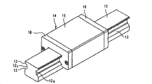
Among Figure 33, the linear guide apparatus of the 6th mode of execution has guide rail 12, slider body 15 and two end caps 16.
Slide block side roll track body face 17 is relative with rail-sides rolling element plane of trajectory orbital 13 respectively, between rail-sides rolling element plane of trajectory orbital 13 and the slide block side roll track body face 17, is formed for making the rolling element load rolling road of rolling element 18 in the length direction rolling of guide rail 2.
In slider body 15, the rolling element that is formed for making along with the linear relative movement of slide block 14 in rolling element load rolling road 19 rolling element 18 that rolls to return returns road 20 (with reference to Figure 41).This rolling element returns road 20 and is formed in the slider body 15 along the length direction of guide rail 2, constitute each end cap 16 of slide block 14 with slide block 15, in each end cap 16, form with rolling element load rolling road 19 and rolling element and return the rolling element direction conversion road 21 (with reference to Figure 41) that road 20 is communicated with.This rolling element direction conversion road 21 bends to roughly U font, and therefore, rolling element load rolling road 19 and rolling element return the rolling element 18 that rolls respectively in the road 20 and change at rolling element direction conversion road 21 travel directions.
Rolling element 18 forms cylindric, and the separation member 22 (with reference to Figure 41) of 18 installations of each rolling element is the vibration that suppresses to be caused by the mutual impact of rotor and the rising of noise level, and is formed by the material softer than rolling element 18 materials (for example resin).In addition, rolling element 18 has the rolling surface cylindraceous 181 (with reference to Figure 41) that rolls on rail-sides rolling element plane of trajectory orbital 13 and slide block side roll track body face 17, the circular-arc rolling element surface of contact 221,222 (with reference to Figure 37) that slides and join with above-mentioned rolling surface 181 is set on separation member 22, and the arm 223 of the axial pairing left and right that moves that suppresses rolling element 18 is set.
Rolling element returns road 20 and rolling element direction conversion road 21 its sections vertical with length direction and forms rectangles, and these rolling elements return the guiding groove 30 (with reference to Figure 34) that formation can engage with the arm 223 of separation member 22 with being free to slide on the internal face on road 20 and rolling element direction conversion road 21.
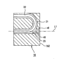
On end cap 16, be provided for pack into the rolling element of slider body 15 of rolling element 18 and separation member 22 is returned through hole 25 (with reference to Figure 35 and 36) in the road 20.This through hole 25 is formed on the end cap 16 coaxially with the elongation line L1 that the prolongation rolling element returns the center line on road 20.In addition, through hole 25 has respectively end face 182 (with reference to Figure 41) two opposite inner walls face 251 (with reference to the Figure 35) with rolling element 18, forms the guiding groove 45 that can engage with the arm 223 of separation member 22 on these internal faces 251 with being free to slide.And then through hole 25 is formed on the end cap 16 to return the roughly the same opening area of the opening area on road 20 with rolling element, is provided with the cover 26 (with reference to Figure 38 and 43) of inaccessible through hole 25 on this end cap 16 detachable.
This cover 26 is chimeric with through hole 25, constitutes the part on the rolling element direction conversion road 21 that forms in the end cap 16.
Through hole 25 is opened on the end face 162 (with reference to Figure 36) with the end cap 16 of slider body 15 opposite sides, forms on the end face 162 of this end cap 16 engage with front end that rolling element shown in Figure 39 inserts anchor clamps 33 and as the hole portion 48 of the positioning part of rolling element being inserted anchor clamps 33 are located and cover 26 being located.This hole portion 48 is with coaxial with through hole 25 and form rectangular than the size of through hole 25 big circles, and the engagement portion 28 (with reference to Figure 38) that engages with above-mentioned hole portion 48 is set on cover 26.
Illustrate that below with reference to Figure 39 the rolling element that uses in the present embodiment inserts anchor clamps 33.
This rolling element inserts anchor clamps 33, as shown in figure 39, is the tubular body of rectangle, and section is identical with the plane shape of step portion 27, and the inboard shape of section is identical with the section shape of through hole 25.Rolling element insertion anchor clamps 33 have end face difference two opposite inner walls face 331 (with reference to the Figure 39) with rolling element 18, and the length direction that these internal face 331 upper edge rolling elements insert anchor clamps 33 is provided with the guiding groove 332 that can engage with the arm 223 of separation member 22 respectively with being free to slide.
In addition, the rolling element length of inserting anchor clamps 33 is configured to insert the length of the such amount of the number of the rolling element 18 in the slide block 14.
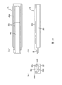
Below, with reference to the assembling method of Figure 40~43 explanation linear guide apparatus.
At first, fix the end cap 16 of a side by bolt 46 at an end of slider body 15 respectively, the other end fixedly opposite side end cap 16 and the assembling slide block 14.Secondly, slide block 14 is installed on the guide rail 12.At this moment, the through hole 25 of end cap 16 be can't help cover 26 obturations, as shown in figure 40, forms the state that the opening end of through hole 25 exposes.
Secondly, inserting anchor clamps 33 with rolling element shown in Figure 39 inserts rolling element 18 and separation member 22 in the slide block 14 from through hole 25.Particularly, at first, behind alternately pack in rolling element inserts anchor clamps 33 a plurality of rolling elements 18 and the separation member 22, length direction one end that rolling element is inserted anchor clamps 33 embeds the through hole 25 that is formed on end cap 16.Then, as shown in figure 41, insert the other end of anchor clamps 33 from rolling element and release a plurality of rolling elements 18 and separation member 22, thereby a plurality of rolling elements 18 and separation member 22 are returned road 20 from the rolling element that through hole 25 is loaded in the slide block 14 continuously.
Thus, alternately being loaded into rolling element from through hole 25 returns road 20 for rolling element 18 and separation member 22.And, being seated in rolling element 18 and the separation member 22 that rolling element returns road 20 and moving, rolling element 18 and separation member 22 are seated in the whole slide block 14.
Secondly, as shown in figure 42, from the through hole 25 of end cap 16 rolling element is inserted anchor clamps 33 and take out.And, as shown in figure 43, cover 26 is embedded through hole 25, by cover 26 inaccessible through holes 25.
Like this, linear guide apparatus according to present embodiment, can rolling element 18 and separation member 22 be loaded in the slide block 14 from the through hole of being located on the cover 16 25, can not use the interim axle 23 shown in Figure 66 and rolling element 18 and separation member 22 are loaded in the slide block 14, so can improve the assembling performance of linear guide apparatus.
In addition, the other end by inserting anchor clamps 33 from the rolling element that is assembled with a plurality of rolling elements 18 and separation member 22 is in advance firmly packed a plurality of rolling elements 18 and separation member 22 in the slide block 14 continuously, thereby can prevent to be loaded in the slide block 14 under the state that separation member 22 tilts.
In the 6th above-mentioned mode of execution, illustration return road 20 along rolling element elongation line L1 the situation of through hole 25 is set on end cap 16, but the centre line L 3 that also can make as shown in figure 44, through hole 25 and rolling element return the elongation line L1 on road 20 and tilt to intersect and through hole 25 is arranged on the end cap 16.In addition, as shown in figure 45, the elongation line L1 that the centre line L 3 that also can make through hole 25 and rolling element return road 20 intersects vertically and through hole 25 is arranged on the end cap 16.
In the 6th above-mentioned mode of execution, as the size formation rectangular of hole portion 48 to enclose than through hole 25 big of the positioning part that cover 26 is positioned, still, the shape of hole portion 48 also can be the shape shown in Figure 46 or 48.In this case, the shape of the engagement portion 28 that is provided with on the cover 26 shape shown in Figure 47 or 49 preferably.
In the above-described 6th embodiment, be arranged on the end face 162 of end cap 16 as hole portion 48, but also can replace hole portion 48 and form slot part 49 (with reference to Figure 50) at the inner face that is formed at the through hole 25 on the end cap 16 with the positioning part of cover 26 location.In this case, the shape of the engagement portion 28 that is provided with on the cover 26 is preferably formed as the shape shown in Figure 51.
In the above-described 6th embodiment, the guiding groove 45 of the arm 223 of guiding separation member 22 is arranged on the internal face 251 of through hole 25, but shown in Figure 52 (a), if the length W2 on the long limit of through hole 25 is not and the axial length W1 of rolling element coincide but and the size W2 of 223 of the arms of separation member 22 identical, then can be not guiding groove 45 be set at the internal face 251 of through hole 25 yet.
In the mode of execution shown in Figure 52 (a), the vertical section of the direction of packing into rolling element 18 and separation member 22 of through hole 25 forms rectangle, but neither form rectangle, but the also shape shape shown in Figure 52 (b)~Figure 52 (e) for example of the section shape of through hole 25.In addition, through hole 25 be under the situation of rectangle with rolling element 18 section vertical with the direction of packing into of separation member 22, be preferably formed as the chamfered section 50 shown in Figure 53 or Figure 54 at least one of four bights of through hole 25.
In addition, through hole 25 has under the situation of guiding groove 45, and shown in Figure 55, the bight chamfer machining of guiding groove 45 becomes circular-arc, and preferably at least one chamfered section 51 is arranged on the through hole 25.
In the mode of execution shown in Figure 35, the bond length of through hole 25 and the diameter of rolling element are roughly the same, but shown in Figure 56, the bond length W4 of through hole 25 also can be local or longer than the diameter W3 of rolling element on the whole.
In the mode of execution shown in Figure 52, size is roughly the same between the long edge lengths of through hole 25 and the arm of separation member, but shown in Figure 57, and the long edge lengths W5 of the through hole 25 also size W2 between the arm of comparable separation member is long.In addition, shown in Figure 58, also can be that the bond length W4 of through hole 25 is local or longer than rolling element diameter W3 on the whole, and the long edge lengths W5 of through hole 25 be longer than the axial length W1 of rolling element.
In mode of execution shown in Figure 41, as the separation member that is loaded between each rolling element, adopt the structure of arm 223 with pairing left and right, but shown in Figure 59, the structure that also can adopt each separation member 22 to link by binding parts 60 with flexual band shape.
In addition, in each above-mentioned mode of execution, illustration rolling element form structure cylindraceous, but rolling element forms under the spherical situation, preferably the vertical section of the filling direction with rolling element and separation member of through hole 25 forms the shape shown in Figure 60 (a)~(g), and the shape of cover 26 forms the shape shown in Figure 61 and 62.
Claims (21)
1. linear guide apparatus, it is provided with: guide rail; Slider body, it has with length direction along above-mentioned guide rail and is formed on the relative rolling element plane of trajectory orbital of rolling element plane of trajectory orbital on the above-mentioned guide rail; End cap, its be provided with the two rolling element plane of trajectory orbital that are formed on above-mentioned guide rail and slider body between rolling element load rolling road be communicated with and run through the rolling element that is arranged in the above-mentioned slider body and return the rolling element direction conversion road that the road is communicated with length direction along above-mentioned guide rail; A plurality of rolling elements, it is followed the linear relative movement of the slide block that is made of above-mentioned slider body and above-mentioned end cap and returns at above-mentioned rolling element load rolling road, rolling element and to roll in road and the rolling element direction conversion road; A plurality of separation members, it is located in above-mentioned a plurality of rolling element between adjacent two rolling elements, it is characterized in that,
Above-mentioned end cap has and is used for above-mentioned rolling element and the above-mentioned separation member above-mentioned rolling element of packing into from the outside of above-mentioned slide block is returned through hole in the road.
2. linear guide apparatus as claimed in claim 1 is characterized in that above-mentioned end cap has the cover of inaccessible above-mentioned through hole.
3. the linear guide apparatus shown in claim 2 is characterized in that, above-mentioned cover and above-mentioned through hole are chimeric and form the part on above-mentioned rolling element direction conversion road.
4. as each described linear guide apparatus of claim 1~3, it is characterized in that above-mentioned rolling element is a roller.
5. as each described linear guide apparatus of claim 1~3, it is characterized in that above-mentioned separation member has the rolling element surface of contact of the concavity that contacts with above-mentioned rolling element.
6. as each described linear guide apparatus of claim 1~3, it is characterized in that above-mentioned separation member comprises the main part that is positioned between above-mentioned rolling element and is configured in the arm of pairing left and right of the both sides of this main part.
7. linear guide apparatus as claimed in claim 6 is characterized in that, above-mentioned through hole has the guiding groove that can engage with the arm of above-mentioned separation member with being free to slide.
8. linear guide apparatus as claimed in claim 6 is characterized in that, above-mentioned rolling element returns the road and above-mentioned rolling element direction conversion road has the guiding groove that can engage with the arm of above-mentioned separation member with being free to slide.
9. as each described linear guide apparatus of claim 1~3, it is characterized in that above-mentioned separation member connects to row by the binding parts with flexual band shape.
10. as each described linear guide apparatus of claim 1~3, it is characterized in that it is relative and be formed on the above-mentioned end cap that above-mentioned through hole and above-mentioned rolling element return the road.
11., it is characterized in that above-mentioned through hole is formed on the above-mentioned end cap coaxially with the elongation line that the above-mentioned rolling element of prolongation returns the center line on road as each described linear guide apparatus of claim 1~3.
12., it is characterized in that above-mentioned through hole is formed on the above-mentioned end cap with the big opening area of opening area that returns the road than above-mentioned rolling element as each described linear guide apparatus of claim 1~3.
13., it is characterized in that above-mentioned through hole is formed on the above-mentioned end cap to return the roughly the same opening area of the opening area on road with above-mentioned rolling element as each described linear guide apparatus of claim 1~3.
14. as each described linear guide apparatus of claim 1~3, it is characterized in that, above-mentioned through hole with prolong elongation line that above-mentioned rolling element returns the center line on road and intersect and be formed on the above-mentioned end cap.
15., it is characterized in that above-mentioned through hole forms and comprises the shape of a part that above-mentioned rolling element returns the section shape on road as each described linear guide apparatus of claim 1~3.
16. linear guide apparatus as claimed in claim 2 is characterized in that, above-mentioned end cap has the positioning part that above-mentioned cover is positioned.
17. linear guide apparatus as claimed in claim 16 is characterized in that, above-mentioned cover has the engagement portion that engages with above-mentioned positioning part.
18. linear guide apparatus as claimed in claim 6, it is characterized in that, above-mentioned rolling element and above-mentioned separation member with have with the side of above-mentioned rolling element or above-mentioned arm respectively the rolling element of two opposite inner walls face insert in anchor clamps pack above-mentioned slide block into from above-mentioned through hole.
19. linear guide apparatus as claimed in claim 18 is characterized in that, above-mentioned rolling element inserts anchor clamps and forms and the chimeric shape of above-mentioned through hole.
20. linear guide apparatus as claimed in claim 19 is characterized in that, the front end that above-mentioned end cap has with above-mentioned rolling element inserts anchor clamps engage the positioning part that above-mentioned rolling element insertion anchor clamps is positioned and above-mentioned cover is positioned.
21., it is characterized in that above-mentioned rolling element is a spheroid as each described linear guide apparatus of claim 1~3.
Applications Claiming Priority (4)
| Application Number | Priority Date | Filing Date | Title |
|---|---|---|---|
| JP407767/2003 | 2003-12-05 | ||
| JP2003407767A JP4561087B2 (en) | 2003-12-05 | 2003-12-05 | Linear guide device and assembly method thereof |
| JP196948/2004 | 2004-07-02 | ||
| JP248507/2004 | 2004-08-27 |
Publications (2)
| Publication Number | Publication Date |
|---|---|
| CN1886601A CN1886601A (en) | 2006-12-27 |
| CN100443752C true CN100443752C (en) | 2008-12-17 |
Family
ID=34729715
Family Applications (1)
| Application Number | Title | Priority Date | Filing Date |
|---|---|---|---|
| CNB2004800355022A Active CN100443752C (en) | 2003-12-05 | 2004-12-06 | Linear guide device |
Country Status (2)
| Country | Link |
|---|---|
| JP (1) | JP4561087B2 (en) |
| CN (1) | CN100443752C (en) |
Families Citing this family (7)
| Publication number | Priority date | Publication date | Assignee | Title |
|---|---|---|---|---|
| EP1770289A2 (en) * | 2005-09-29 | 2007-04-04 | NSK Ltd. | Linear rolling element bearing and belt-type cage to accommodate the rolling elements of the linear bearing |
| CN102294840A (en) * | 2011-08-12 | 2011-12-28 | 成都科盛石油科技有限公司 | Sliding platform of pressure machine |
| JP5720635B2 (en) * | 2011-08-23 | 2015-05-20 | 日本精工株式会社 | Guide device |
| JP6115027B2 (en) * | 2012-05-24 | 2017-04-19 | 日本精工株式会社 | Linear guide assembly apparatus and assembly method |
| CN102748387B (en) * | 2012-07-29 | 2015-06-17 | 江苏鸿业重工有限公司 | Linear guide rail auxiliary |
| CN103192112A (en) * | 2013-03-18 | 2013-07-10 | 常州宝菱重工机械有限公司 | Tooling for processing multiple holes in workpiece circumference |
| TWI668378B (en) * | 2018-04-23 | 2019-08-11 | 直得科技股份有限公司 | Miniature linear slide and its slide |
Citations (2)
| Publication number | Priority date | Publication date | Assignee | Title |
|---|---|---|---|---|
| JPS60139912A (en) * | 1983-12-28 | 1985-07-24 | Tsubakimoto Seikou:Kk | Roller type bearing for linear motion |
| JPH02283913A (en) * | 1989-03-31 | 1990-11-21 | Deutsche Star Gmbh | Direct acting ball bearing having ball filling recessed part |
Family Cites Families (3)
| Publication number | Priority date | Publication date | Assignee | Title |
|---|---|---|---|---|
| JPH04283032A (en) * | 1991-03-06 | 1992-10-08 | Mitsubishi Pencil Co Ltd | Assembling part of ball bearing for linear sliding movement |
| JP3426733B2 (en) * | 1994-10-14 | 2003-07-14 | Thk株式会社 | Linear guide device |
| EP1193422B1 (en) * | 2000-09-29 | 2004-01-21 | THK Co., Ltd. | Screw assembly having deflector and method of manufacturing same |
-
2003
- 2003-12-05 JP JP2003407767A patent/JP4561087B2/en not_active Expired - Lifetime
-
2004
- 2004-12-06 CN CNB2004800355022A patent/CN100443752C/en active Active
Patent Citations (2)
| Publication number | Priority date | Publication date | Assignee | Title |
|---|---|---|---|---|
| JPS60139912A (en) * | 1983-12-28 | 1985-07-24 | Tsubakimoto Seikou:Kk | Roller type bearing for linear motion |
| JPH02283913A (en) * | 1989-03-31 | 1990-11-21 | Deutsche Star Gmbh | Direct acting ball bearing having ball filling recessed part |
Also Published As
| Publication number | Publication date |
|---|---|
| JP2005164008A (en) | 2005-06-23 |
| CN1886601A (en) | 2006-12-27 |
| JP4561087B2 (en) | 2010-10-13 |
Similar Documents
| Publication | Publication Date | Title |
|---|---|---|
| EP0318980B1 (en) | Linear motion ball bearing | |
| CN100443752C (en) | Linear guide device | |
| JPH034021A (en) | Linear movement bearing | |
| US6874939B2 (en) | Circulation member, motion guide device provided with circulation member and ball screw provided with circulation member | |
| US4648726A (en) | Linear guide device | |
| EP1304492A1 (en) | Linear motion guide device | |
| ES2377799T3 (en) | POSITIONING DEVICE WITH BEARING MECHANISM. | |
| CN103097752B (en) | Linear motion device | |
| JPH109264A (en) | Slide guide device and its rolling element chain with end | |
| EP0164540B1 (en) | Bearing for linear motion | |
| CN104081069A (en) | Linear guide device | |
| KR20130094354A (en) | Motion guide device and attachment for motion guide device | |
| CA2038660C (en) | Linear motion bearing | |
| CN102713318A (en) | Linear motion guide device | |
| US7341378B2 (en) | Linear motion guide unit | |
| CN1161930A (en) | Conveyer chain with sealing-plug-type hinge-pin-keeping device | |
| JP4537588B2 (en) | Linear motion guidance unit | |
| CN103732930B (en) | Guiding device | |
| US8888367B2 (en) | Linear motion guide unit | |
| JPS6233140Y2 (en) | ||
| EP1801434A1 (en) | Movement guiding device | |
| CN105121874A (en) | Rolling guide device | |
| WO1997040279A1 (en) | Slot bearing | |
| JP2012140996A (en) | End cap, oil passage unit, and linear guide device equipped with end cap | |
| EP3279116A1 (en) | Conveyor chain |
Legal Events
| Date | Code | Title | Description |
|---|---|---|---|
| C06 | Publication | ||
| PB01 | Publication | ||
| C10 | Entry into substantive examination | ||
| SE01 | Entry into force of request for substantive examination | ||
| C14 | Grant of patent or utility model | ||
| GR01 | Patent grant |