CN100435575C - Image processing apparatus and control method - Google Patents
Image processing apparatus and control method Download PDFInfo
- Publication number
- CN100435575C CN100435575C CNB2005100075329A CN200510007532A CN100435575C CN 100435575 C CN100435575 C CN 100435575C CN B2005100075329 A CNB2005100075329 A CN B2005100075329A CN 200510007532 A CN200510007532 A CN 200510007532A CN 100435575 C CN100435575 C CN 100435575C
- Authority
- CN
- China
- Prior art keywords
- mentioned
- image
- date
- time information
- synthesized
- Prior art date
- Legal status (The legal status is an assumption and is not a legal conclusion. Google has not performed a legal analysis and makes no representation as to the accuracy of the status listed.)
- Expired - Fee Related
Links
Images


Classifications
-
- G—PHYSICS
- G06—COMPUTING; CALCULATING OR COUNTING
- G06T—IMAGE DATA PROCESSING OR GENERATION, IN GENERAL
- G06T11/00—2D [Two Dimensional] image generation
- G06T11/60—Editing figures and text; Combining figures or text
-
- G—PHYSICS
- G06—COMPUTING; CALCULATING OR COUNTING
- G06F—ELECTRIC DIGITAL DATA PROCESSING
- G06F3/00—Input arrangements for transferring data to be processed into a form capable of being handled by the computer; Output arrangements for transferring data from processing unit to output unit, e.g. interface arrangements
- G06F3/12—Digital output to print unit, e.g. line printer, chain printer
- G06F3/1201—Dedicated interfaces to print systems
- G06F3/1202—Dedicated interfaces to print systems specifically adapted to achieve a particular effect
- G06F3/1203—Improving or facilitating administration, e.g. print management
- G06F3/1208—Improving or facilitating administration, e.g. print management resulting in improved quality of the output result, e.g. print layout, colours, workflows, print preview
-
- G—PHYSICS
- G06—COMPUTING; CALCULATING OR COUNTING
- G06F—ELECTRIC DIGITAL DATA PROCESSING
- G06F3/00—Input arrangements for transferring data to be processed into a form capable of being handled by the computer; Output arrangements for transferring data from processing unit to output unit, e.g. interface arrangements
- G06F3/12—Digital output to print unit, e.g. line printer, chain printer
- G06F3/1201—Dedicated interfaces to print systems
- G06F3/1202—Dedicated interfaces to print systems specifically adapted to achieve a particular effect
- G06F3/1211—Improving printing performance
- G06F3/1212—Improving printing performance achieving reduced delay between job submission and print start
- G06F3/1213—Improving printing performance achieving reduced delay between job submission and print start at an intermediate node or at the final node
-
- G—PHYSICS
- G06—COMPUTING; CALCULATING OR COUNTING
- G06F—ELECTRIC DIGITAL DATA PROCESSING
- G06F3/00—Input arrangements for transferring data to be processed into a form capable of being handled by the computer; Output arrangements for transferring data from processing unit to output unit, e.g. interface arrangements
- G06F3/12—Digital output to print unit, e.g. line printer, chain printer
- G06F3/1201—Dedicated interfaces to print systems
- G06F3/1202—Dedicated interfaces to print systems specifically adapted to achieve a particular effect
- G06F3/1218—Reducing or saving of used resources, e.g. avoiding waste of consumables or improving usage of hardware resources
- G06F3/122—Reducing or saving of used resources, e.g. avoiding waste of consumables or improving usage of hardware resources with regard to computing resources, e.g. memory, CPU
-
- G—PHYSICS
- G06—COMPUTING; CALCULATING OR COUNTING
- G06F—ELECTRIC DIGITAL DATA PROCESSING
- G06F3/00—Input arrangements for transferring data to be processed into a form capable of being handled by the computer; Output arrangements for transferring data from processing unit to output unit, e.g. interface arrangements
- G06F3/12—Digital output to print unit, e.g. line printer, chain printer
- G06F3/1201—Dedicated interfaces to print systems
- G06F3/1223—Dedicated interfaces to print systems specifically adapted to use a particular technique
- G06F3/1237—Print job management
- G06F3/1253—Configuration of print job parameters, e.g. using UI at the client
- G06F3/1254—Automatic configuration, e.g. by driver
-
- G—PHYSICS
- G06—COMPUTING; CALCULATING OR COUNTING
- G06F—ELECTRIC DIGITAL DATA PROCESSING
- G06F3/00—Input arrangements for transferring data to be processed into a form capable of being handled by the computer; Output arrangements for transferring data from processing unit to output unit, e.g. interface arrangements
- G06F3/12—Digital output to print unit, e.g. line printer, chain printer
- G06F3/1201—Dedicated interfaces to print systems
- G06F3/1278—Dedicated interfaces to print systems specifically adapted to adopt a particular infrastructure
- G06F3/128—Direct printing, e.g. sending document file, using memory stick, printing from a camera
-
- H—ELECTRICITY
- H04—ELECTRIC COMMUNICATION TECHNIQUE
- H04N—PICTORIAL COMMUNICATION, e.g. TELEVISION
- H04N1/00—Scanning, transmission or reproduction of documents or the like, e.g. facsimile transmission; Details thereof
- H04N1/00127—Connection or combination of a still picture apparatus with another apparatus, e.g. for storage, processing or transmission of still picture signals or of information associated with a still picture
- H04N1/00278—Connection or combination of a still picture apparatus with another apparatus, e.g. for storage, processing or transmission of still picture signals or of information associated with a still picture with a printing apparatus, e.g. a laser beam printer
-
- H—ELECTRICITY
- H04—ELECTRIC COMMUNICATION TECHNIQUE
- H04N—PICTORIAL COMMUNICATION, e.g. TELEVISION
- H04N1/00—Scanning, transmission or reproduction of documents or the like, e.g. facsimile transmission; Details thereof
- H04N1/23—Reproducing arrangements
- H04N1/2307—Circuits or arrangements for the control thereof, e.g. using a programmed control device, according to a measured quantity
- H04N1/233—Circuits or arrangements for the control thereof, e.g. using a programmed control device, according to a measured quantity according to characteristics of the data to be reproduced, e.g. number of lines
-
- H—ELECTRICITY
- H04—ELECTRIC COMMUNICATION TECHNIQUE
- H04N—PICTORIAL COMMUNICATION, e.g. TELEVISION
- H04N1/00—Scanning, transmission or reproduction of documents or the like, e.g. facsimile transmission; Details thereof
- H04N1/23—Reproducing arrangements
- H04N1/2307—Circuits or arrangements for the control thereof, e.g. using a programmed control device, according to a measured quantity
- H04N1/2376—Inhibiting or interrupting a particular operation or device
-
- H—ELECTRICITY
- H04—ELECTRIC COMMUNICATION TECHNIQUE
- H04N—PICTORIAL COMMUNICATION, e.g. TELEVISION
- H04N1/00—Scanning, transmission or reproduction of documents or the like, e.g. facsimile transmission; Details thereof
- H04N1/32—Circuits or arrangements for control or supervision between transmitter and receiver or between image input and image output device, e.g. between a still-image camera and its memory or between a still-image camera and a printer device
- H04N1/32101—Display, printing, storage or transmission of additional information, e.g. ID code, date and time or title
- H04N1/32128—Display, printing, storage or transmission of additional information, e.g. ID code, date and time or title attached to the image data, e.g. file header, transmitted message header, information on the same page or in the same computer file as the image
-
- H—ELECTRICITY
- H04—ELECTRIC COMMUNICATION TECHNIQUE
- H04N—PICTORIAL COMMUNICATION, e.g. TELEVISION
- H04N2101/00—Still video cameras
-
- H—ELECTRICITY
- H04—ELECTRIC COMMUNICATION TECHNIQUE
- H04N—PICTORIAL COMMUNICATION, e.g. TELEVISION
- H04N2201/00—Indexing scheme relating to scanning, transmission or reproduction of documents or the like, and to details thereof
- H04N2201/0077—Types of the still picture apparatus
- H04N2201/0084—Digital still camera
-
- H—ELECTRICITY
- H04—ELECTRIC COMMUNICATION TECHNIQUE
- H04N—PICTORIAL COMMUNICATION, e.g. TELEVISION
- H04N2201/00—Indexing scheme relating to scanning, transmission or reproduction of documents or the like, and to details thereof
- H04N2201/32—Circuits or arrangements for control or supervision between transmitter and receiver or between image input and image output device, e.g. between a still-image camera and its memory or between a still-image camera and a printer device
- H04N2201/3201—Display, printing, storage or transmission of additional information, e.g. ID code, date and time or title
- H04N2201/3212—Display, printing, storage or transmission of additional information, e.g. ID code, date and time or title of data relating to a job, e.g. communication, capture or filing of an image
- H04N2201/3214—Display, printing, storage or transmission of additional information, e.g. ID code, date and time or title of data relating to a job, e.g. communication, capture or filing of an image of a date
-
- H—ELECTRICITY
- H04—ELECTRIC COMMUNICATION TECHNIQUE
- H04N—PICTORIAL COMMUNICATION, e.g. TELEVISION
- H04N2201/00—Indexing scheme relating to scanning, transmission or reproduction of documents or the like, and to details thereof
- H04N2201/32—Circuits or arrangements for control or supervision between transmitter and receiver or between image input and image output device, e.g. between a still-image camera and its memory or between a still-image camera and a printer device
- H04N2201/3201—Display, printing, storage or transmission of additional information, e.g. ID code, date and time or title
- H04N2201/3212—Display, printing, storage or transmission of additional information, e.g. ID code, date and time or title of data relating to a job, e.g. communication, capture or filing of an image
- H04N2201/3215—Display, printing, storage or transmission of additional information, e.g. ID code, date and time or title of data relating to a job, e.g. communication, capture or filing of an image of a time or duration
-
- H—ELECTRICITY
- H04—ELECTRIC COMMUNICATION TECHNIQUE
- H04N—PICTORIAL COMMUNICATION, e.g. TELEVISION
- H04N2201/00—Indexing scheme relating to scanning, transmission or reproduction of documents or the like, and to details thereof
- H04N2201/32—Circuits or arrangements for control or supervision between transmitter and receiver or between image input and image output device, e.g. between a still-image camera and its memory or between a still-image camera and a printer device
- H04N2201/3201—Display, printing, storage or transmission of additional information, e.g. ID code, date and time or title
- H04N2201/3261—Display, printing, storage or transmission of additional information, e.g. ID code, date and time or title of multimedia information, e.g. a sound signal
- H04N2201/3266—Display, printing, storage or transmission of additional information, e.g. ID code, date and time or title of multimedia information, e.g. a sound signal of text or character information, e.g. text accompanying an image
-
- H—ELECTRICITY
- H04—ELECTRIC COMMUNICATION TECHNIQUE
- H04N—PICTORIAL COMMUNICATION, e.g. TELEVISION
- H04N2201/00—Indexing scheme relating to scanning, transmission or reproduction of documents or the like, and to details thereof
- H04N2201/32—Circuits or arrangements for control or supervision between transmitter and receiver or between image input and image output device, e.g. between a still-image camera and its memory or between a still-image camera and a printer device
- H04N2201/3201—Display, printing, storage or transmission of additional information, e.g. ID code, date and time or title
- H04N2201/3271—Printing or stamping
-
- H—ELECTRICITY
- H04—ELECTRIC COMMUNICATION TECHNIQUE
- H04N—PICTORIAL COMMUNICATION, e.g. TELEVISION
- H04N2201/00—Indexing scheme relating to scanning, transmission or reproduction of documents or the like, and to details thereof
- H04N2201/32—Circuits or arrangements for control or supervision between transmitter and receiver or between image input and image output device, e.g. between a still-image camera and its memory or between a still-image camera and a printer device
- H04N2201/3201—Display, printing, storage or transmission of additional information, e.g. ID code, date and time or title
- H04N2201/3273—Display
Abstract
An image processing apparatus which is connected to a printer apparatus and controls the printer apparatus to print a shot image, includes an image sensing unit for shooting an image, a setting reception unit for receiving settings as to whether or not date information of shooting is to be added to the image shot by the image sensing unit, an addition unit for adding the date information to the image shot by the image sensing unit on the basis of the received settings, an identifier generation unit for generating an identifier, which is used to identify whether or not the date information is added to the shot image and to limit a printing condition of the printer apparatus, on the basis of the received settings, and appending the identifier to a header of the shot image, and a transmission unit for transmitting the image having the header appended with the identifier to the printer apparatus.
Description
Technical field
The present invention relates to a kind of image processing apparatus of the dual printing of date that prevents from when print image, will be added on the date on the image and in printing equipment, add.
Background technology
In the past, with the photographic equipment of digital camera, Digital Video etc. with telecommunication cable or the wireless system that is connected with printing equipment or constitutes integratedly in, can be not by process computer etc. image information messaging device and the image information that photographic equipment is captured is printed.
Print in the such photographic equipment of captured image information can connecting printing equipment, can select and carry out that paper setting, date printed are set, number is set such print setting by the image that photographic equipment carry out printing.In addition, can in photographic equipment, elect the date print setting as unlatching (ON), thus the shooting date in printing equipment on the additional storage medium.
In addition, at photographic equipment itself, also can implement shooting date and time are added in the image as through image information, and be recorded on the recording medium.
; to be connected with printing equipment as above-mentioned example in the past with this digital camera image captured, that added the date when printing; because shooting date adds to the image in camera one side as image information from beginning; so; when setting by date printed when carrying out the printing of shooting date, make an addition to the date in the image and the additional date will be by dual printing in printing equipment at digital camera itself with printing equipment.
That is, the objective of the invention is to, prevent that date and time information is by dual printing when printing captured image.
Summary of the invention
The present invention who addresses the above problem is connected with printing equipment, and the above-mentioned printing equipment of may command is printed the image processing apparatus of captured image, and possess: camera head is used for photographic images; Set receiving device, the date and time information of having accepted whether will carry out to take is synthesized to the setting by the captured image of above-mentioned camera head; Synthesizer, the setting based on above-mentioned setting receiving device is accepted is synthesized to above-mentioned date and time information by the captured image of above-mentioned camera head; The identifying information generating apparatus, when date information is synthesized to above-mentioned captured image, based on the above-mentioned setting of accepting, generate the identifying information of the print conditions be used to limit above-mentioned printing equipment, the identifying information that is generated is appended in the title of above-mentioned captured image; And conveyer, will have the image of the title that has added above-mentioned identifying information, transmit to above-mentioned printing equipment.
The present invention who is used for further addressing the above problem is the image processing apparatus of printable captured image, and possess: camera head is used for photographic images; Set receiving device, the date and time information of having accepted whether will carry out to take is synthesized to the setting by the captured image of above-mentioned camera head; Synthesizer, the setting based on above-mentioned setting receiving device is accepted is synthesized to above-mentioned date and time information by the captured image of above-mentioned camera head; The identifying information generating apparatus when date information is synthesized on the above-mentioned captured image, generates the identifying information that is used to limit print conditions based on the above-mentioned setting accepted, the identifying information that is generated is appended in the title of above-mentioned captured image; And printing equipment, print image.
The present invention who is used for further solving above-mentioned problem be can print image printing equipment, possess: judgment means, judge whether the date and time information of the shooting of having carried out above-mentioned image is synthesized to above-mentioned image; The print conditions setting device when being judged as above-mentioned date and time information when being synthesized to above-mentioned image in above-mentioned judgment means, is set print conditions, makes synthetic to above-mentioned image that suppresses the above-mentioned date and time information in the above-mentioned printing equipment; And printing equipment, print based on the above-mentioned print conditions that sets.
Other features and advantages of the present invention will become in the following explanation of carrying out with reference to the accompanying drawings clearly, and in institute's drawings attached, same or analogous part adopts same-sign.
Description of drawings
Be contained in this specification and constitute its a part of accompanying drawing and be used to describe embodiments of the present invention, and explain principle of the present invention with specification.
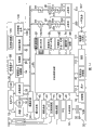
Figure 1A is the block diagram of an example of the structure of the expression image processing apparatus corresponding with embodiments of the present invention.
Figure 1B is the block diagram of an example of the structure of the expression printing equipment corresponding with embodiments of the present invention.
Fig. 2 is the starting in the image processing apparatus 100 corresponding with embodiments of the present invention and takes the flow chart of an example of action.
Fig. 3 is the starting in the image processing apparatus 100 corresponding with embodiments of the present invention and takes the flow chart of an example of action.
Fig. 4 is the flow chart of an example of range finding in the image processing apparatus 100 corresponding with embodiments of the present invention and photometry program.
Fig. 5 is the flow chart of an example of the photographing program in the image processing apparatus 100 corresponding with embodiments of the present invention.
Fig. 6 is the flow chart of an example of the logging program in the image processing apparatus 100 corresponding with embodiments of the present invention.
Fig. 7 A adds the figure of an example of information on the expression date corresponding with embodiments of the present invention.
Fig. 7 B is the figure of an example of the expression coordinate position that add date and time information in view data corresponding with embodiments of the present invention.
The flow chart of one example of the action when Fig. 8 is printing in the image processing apparatus 100 corresponding with embodiments of the present invention.
Fig. 9 is the flow chart of an example of the initial setting program in the image processing apparatus 100 corresponding with embodiments of the present invention.
Figure 10 is a flow chart of the date in the image processing apparatus 100 corresponding with embodiments of the present invention printing an example of determining program.
Figure 11 is an example of the print setting picture in the image processing apparatus 100 corresponding with embodiments of the present invention.
Figure 12 is used to illustrate the figure that the side cut of the image corresponding with embodiments of the present invention is handled
Embodiment
Describe the preferred embodiments of the present invention below with reference to the accompanying drawings in detail.
Figure 1A is the block diagram of the structure of expression an embodiment of the invention.In Figure 1A, the 100th, image processing apparatus.The 10th, capture lens, the 12nd, possess the shutter of aperture function, the 14th, convert optical imagery the capturing element of the signal of telecommunication to, the 16th, the analog signal conversion of capturing element 14 is become the A/D converter of digital signal.
The 18th, clock signal and control signal are supplied to the timing generating circuit of capturing element 14, A/D converter 16, D/A converter 26, control by storage control circuit 22 and system, control circuit 50.
The 20th, image processing circuit is to handling and color conversion processing from the data of A/D converter 16 or from the pixel interpolating that the data of storage control circuit 22 are scheduled to.And then graphic processing circuit 20 also can add the date to image by the synthetic processing of carrying out the date image.
In addition, in image processing circuit 20, the calculation process that is to use captured view data to be scheduled to, according to the operation result that obtains, 50 pairs of exposure control circuits 40 of system, control circuit, range finding control circuit 42 are controlled, and carry out AF (the auto focus: automatic focus) processing, AE (auto exposure: automatic exposure) processing, AWB (auto white balance: Automatic white balance) processing, EF (flash pre emission: flash of light preflashing) handle of TTL (through the lens: pass through camera lens) mode.
The 22nd, storage control circuit, control A/D converter 16, timing generating circuit 18, image processing circuit 20, image display-memory 24, D/A converter 26, memory 30, compression/expansion circuit 32.
The data of A/D converter 16 are via image processing circuit 20, storage control circuit 22, and perhaps the data of A/D converter 16 write image display-memory 24 or memory 30 directly via storage control circuit 22.
The 24th, the image display-memory, the 26th, D/A converter, the 28th, by the image displaying part that TFT LCD etc. constitutes, the view data that writes the demonstration usefulness of image display-memory 24 is shown by image displaying part 28 via D/A converter.In addition, if use image displaying part 28 to show captured view data one by one, just can realize the function of electronic viewfinder.
The 30th, be used to store the rest image of shooting and the memory of dynamic image, for the rest image of storing predetermined number and the dynamic image of the scheduled time and possess enough memory spaces.Thus, when taking the sequence photography of many rest images and panoramic shooting continuously, can carry out high speed and jumbo image writes to memory 30.In addition, even memory 30 also can use as the operating area of circuit system 50.
The 32nd, the compression/expansion circuit according to adapting to the isobaric reducing and expansion exhibition of discrete cosine transform (ADCT) view data reads in the image that is stored in memory 30 and compresses or extension process, with the writing data into memory 30 that is through with and handles.
The 40th, control possesses the exposure control circuit of shutter 12 of aperture function, by cooperating with flash of light 48, thereby also has the flash of light dimming function.The 42nd, the range finding control circuit of the focusing of control capture lens 10, the 44th, the varifocal control circuit of the varifocal of control capture lens 10, the 46th, the control baffle plate is the baffle controls circuit of the action of protective circuit 102.
The 48th, glisten, also have light projector function, the flash of light dimming function of AF fill-in light.Exposure control circuit 40, range finding control circuit 42 use the TTL mode to control, according to the operation result that utilizes 20 pairs of shot image data of image processing circuit to carry out computing, 50 pairs of exposure control circuits 40 of system, control circuit, range finding control circuit 42 are controlled.
The 50th, the system, control circuit of control image processing apparatus 100 integral body, the 52nd, the memory of the constant of the action usefulness of storage system control circuit 50, variable, program etc.The 54th, according to the program implementation in system, control circuit 50, use character, image, sound etc., the display part of the liquid crystal indicator of display action state and message etc., loud speaker etc., near the position of seeing easily the operating portion of image processing apparatus 100 is provided with a place or many places, for example is made of combinations such as LCD, LED, pronunciation components.In addition, display part 54, its part of functions is arranged in the optical finder 104.
In the displaying contents of display part 54, content as being presented at LCD etc. has: individual/take continuously and show, self timing shows, compression ratio shows, the recording pixel digital display shows, the record number shows, remaining photographic number shows, shutter speed shows, f-number shows, exposure correction shows, flash of light shows, blood-shot eye illness is eliminated and is shown, low coverage (macro) is taken and is shown, buzzer is set and is shown, clock shows with residual capacity of battery, residual capacity of battery shows, mistake shows, utilize the information of long number to show, recording medium 200 shows with 210 be connected/released state, communication I/F action shows, date demonstration etc.In addition, in the displaying contents of display part 54, as content displayed in optical finder 104, have: focusing shows, vibratory alarm shows, demonstration, shutter speed demonstration, f-number demonstration, exposure correction demonstration etc. are charged in flash of light.
The 56th, the nonvolatile memory of electric erasable/record for example uses EPROM etc.60,62,64,66,68 and 70 is the operating portions that are used for the exercises indication of input system control circuit 50, is made of one or more combinations of switch, dial, touch panel, the pointer that utilizes visual detection, voice recognition device etc.
Carry out the specific description of these operating portions here.The 60th, the mode dial switch can be set, with each functional modes such as Switching power disconnection, automatic shooting pattern, screening-mode, pan-shot pattern, replay mode, many picture playbacks/elimination pattern, PC connection modes.
The 62nd, shutter release SW1 does not open in having the operation way of illustrated shift knob, and indication AF (automatic focus) handles, AE (automatic exposure) handles, AWB (Automatic white balance) handles, EF (flash of light preflashing) handles.
The 64th, shutter release SW2, after the operation that does not have illustrated shift knob, become unlatching, indicate the action of a series of processing to begin, these a series of processing, that is: the signal that will read from capturing element is via A/D converter 16, storage control circuit 22, the exposure-processed of view data write memory 30; Used the development treatment and the date of the computing in image processing circuit 20 and storage control circuit 22 to add processing; Read view data from memory 30, compress, the recording processing of view data writing recording medium 200 or 210 at compression/expansion circuit 32.
The 66th, image shows on/off switch, can set the On/Off of image displaying part 28.Function thus when using optical finder 104 to photograph, by by the electric current supply to the image displaying part that is made of TTL LCD etc., can be sought the saving of electric power.
The 68th, the date is added on/off switch, adds the function on date in the time of can setting photography in shot image data.Here, switch 68 adds the setting on date to view data when " unlatching ", when " closing ", view data is not added the setting on date.
The 70th, the operating portion by various buttons, touch panel etc. constitute has: menu button, button, low coverage button, many picture playbacks are set add page or leaf (new page) button, flash of light and set button, the single bat/continuously bats/self-timer switching push button, menu and move+(just) button, menu moves-(bear) button, reproduced picture move+(just) button, reproduced picture move-(bearing) button, shooting image quality selector button, exposure correction button, date setting button etc.
The 80th, power control circuit, constitute by battery detection circuit, DC-DC transducer, the switching circuit etc. that switches the section of energising, carry out the having or not of installation of battery, the kind of battery, the detection of residual capacity of battery, indication according to testing result and system, control circuit 50, control DC-DC transducer is supplied with required voltage during needs to each unit that comprises recording medium.
82 and 84 is connectors, the 86th, and the power circuit that constitutes by secondary cell, AC adapters etc. such as primary cells such as alkaline battery, lithium battery and NiCd battery, NiMH battery, Li batteries.
90 and 94 is the interfaces that are connected with the interface of storage card and recording mediums such as hard disk, and 92 and 96 is the connectors that are connected with recording mediums such as hard disks with storage card.
And, in the present embodiment, interface and the connector that recording medium is installed described as the parts that 2 systems have.Certainly, the interface and the connector of installation recording medium also can be to possess structure one or more, arbitrary number.In addition, also can be to possess the interface of combination different size and the structure of connector.As interface and connector, also can use element to constitute according to specifications such as pcmcia card and CF (Compact Flash (registered trade mark)) cards.
Further, when using element according to specifications such as pcmcia card, CF (Compact Flash (registered trade mark)) cards to constitute interface 90 and 94, connector 92 and 96, by connecting the various communication cards such as communication card of LAN card, nextport modem card NextPort, USB card, IEEE1394 card, P1284 card, SCSI card, PHS etc., can and other computer and peripheral equipment such as printer between, transmitted image data and be attached to the management information of view data.
The 98th, clock by internal electric source (not diagram) continuous action, is recorded in the shooting date acquisition of image header etc. when being used to take.The 102nd, the i.e. protection of baffle plate portion.Described baffle plate comprises by covering and the shoot part of the lens 10 of image processing apparatus 100 prevents the dirt and the damage of shoot part.
The 104th, optical finder can not use the electronic viewfinder function of image displaying part 28, and only use optical finder to photograph.In addition, in optical finder, the partial function of display part 54 for example is provided with focusing demonstration, vibratory alarm demonstration, flash of light charging demonstration, shutter speed demonstration, f-number demonstration, exposure correction demonstration etc.
The 110th, telecommunication circuit, have various communication functions such as RS232 and USB, IEEE1394, P1284, SCSI, modulator-demodulator, LAN, radio communication, image processing apparatus 100 and printing equipment 600 are connected with private cable, utilize telecommunication circuit 110 to communicate, also can operating operation portion 70 come print image.
The 112nd, the connector that utilizes telecommunication circuit 110 to wait other equipment to be connected image processing apparatus 100 and printing equipment 600 perhaps, is antenna under the situation of radio communication.The 120th, the print data generative circuit when connecting image processing apparatus 100 and printing equipment 600 and print, generates the print data that sends to printing equipment 600.The print data that is generated is sent to printing equipment 600 by telecommunication circuit 110 and prints.
The 200th, the recording medium of storage card, hard disk etc.Recording medium 200 possesses: the recording portion 202 that is made of semiconductor memory, disk etc., the interface 204 that is connected with image processing apparatus 100, and the connector 206 that is connected with image processing apparatus 100.
The 210th, the recording medium of storage card, hard disk etc.Recording medium 210 possesses: the recording portion 212 that is made of semiconductor memory, disk etc., the interface 214 that is connected with image processing apparatus 100, and the connector 216 that is connected with image processing apparatus 100.
The printing equipment 600 corresponding with present embodiment shown in Figure 1B, has: CPU601, ROM602, RAM603, press key input device 604, display unit 605, information acquisition device 607, printing equipment 608 and external connection device 609.
In said structure, in CPU601, carry out the various programs be stored in ROM602, as required, in RAM603, write, the processing of visit data.
ROM602 is writeable nonvolatile memory, and storage is used to control program, the program that is used to handle and the data of above-mentioned each device.RAM603 writes or visits needed data along with the program implementation that is stored in RAM602.In press key input device 604, in printing equipment 600, be used to impel the execution indication input of the execution of various functions.Indicate based on this and to carry out processing.
In display unit 605, the demonstration that is stored in the video data of RAM603 is handled.In the affirmation of carrying out function is handled, except the demonstration of the function name that becomes the function of confirming object with carry out showing the demonstration of the Print Preview in handling, also show needed information at Print Preview.Information acquisition device 606 be used to read be stored in the information acquisition medium information (for example, with Compact Flash (registered trade mark) and move media is the storage medium of representative) device, can obtain in captured view data such as image processing apparatus 100 from this information acquisition medium.This information acquisition device 606 can be built in print processing device, also can connect by wired or wireless.
With reference to Fig. 2~Fig. 6, the unlatching of the image processing apparatus corresponding with present embodiment 100 is described and takes action.Fig. 2 and Fig. 3 represent the unlatching of the image processing apparatus corresponding with present embodiment 100 and the flow chart of photographing program.
At first, utilize battery swap to wait energized, thereby system, control circuit 50 show initialization such as mark and control variables (S101) to be initially set closed condition (S102) with the image of image displaying part 28.
The desired location of system, control circuit 50 judgment model dials 60; if being set at power supply, mode dial 60 disconnects (S103); just the demonstration with each display part changes to done state; close the baffle plate of protection portion 102; the protection shoot part; to comprise the parameters needed of mark and control variables and set point, setting mode record in nonvolatile memory; pass through power control circuit; disconnect (S105) after the predetermined end process of unwanted power supply etc. of image processing apparatus 100 each unit that comprise image displaying part 28, turn back to S103.
If mode dial 60 is set at screening-mode (being " screening-mode " in S103), just enter S106.If mode dial 60 is set at other patterns (being " other patterns " in S103), system, control circuit 50 is just carried out the processing (S104) corresponding with selecteed pattern, if be through with processing, just turns back to S103.
System, control circuit 50, judge the residual capacity of the power supply 86 that constitutes by battery etc. and action situation in the action of image processing apparatus 100, whether have problems (S106) by power control circuit, if problem is arranged, the warning of just using display part to utilize image and sound to be scheduled to shows back (S108), turns back to S103.
If the operate condition of recording medium 200 or 210 no problem (S107) just enters S109.
Because do not set the date (S109), just can not add the date, write mark (S112) so just remove.If set the date (S109), system, control circuit 50 is just adjusted the date and is added the set condition (S110) of on/off switch 68, add opening if be set at the date, just set the date and add mark (S111), add closed condition if be set at the date, just remove and write mark (S112).And the date is added the state storage of mark in the internal storage or memory 52 of system, control circuit 50.
At this, what is called writes mark, be meant in order whether date and time information to be synthesized to the image of shooting in the photographing process that is identified in S129, and in the recording processing of S134, whether the information relevant with the date and time information that is synthesized to image appended to the title division of image and the identifying information that uses.
Then, system, control circuit 50 is adjusted the set condition (S113) that image shows on/off switch 66, show unlatching if be set at image, just set image show tags (S114), and with the image display setting of image displaying part 28 is opening (S115), and then be set at perspective demonstration (through display) state (S116) that shows captured view data one by one, enter S119.
In the perspective show state, via capturing element 12, A/D converter 16, image processing circuit 20, storage control circuit 22, to be written to the data of image display-memory 24 one by one via storage control circuit 22, D/A converter 26, show one by one by image displaying part 28, realize electronic viewfinder function thus.
If image shows that on/off switch 66 is set at image and shows and close (S113), just remove image show tags (S117), and be closed condition (S118) the image display setting of image displaying part 28, enter S119.
Image shows when closing, and does not use the electronic viewfinder function of image displaying part 28, uses optical finder 104 to take.At this moment, can reduce the power consumption of the big image displaying part of power consumption 28, D/A converter 26 etc.And the state storage of image show tags is at the internal storage or the memory 52 of system, control circuit 50.
Switch SW 1 (S119) does not just turn back to S103 if do not trip.If pressed shutter release SW1 (S119), system, control circuit 50 is just judged the internal storage of system, control circuit 50 or the image show tags state (S120) of memory 52 of being stored in, if set the image show tags, just the show state of image displaying part 28 is set at and freezes show state (S121), enter S122.
In freezing show state (S121), forbid view data rewriting via the image display-memory 24 of capturing element 12, A/D converter 16, image processing circuit 20, storage control circuit 22, with the view data that writes at last via storage control circuit 22, D/A converter 26, show that by image displaying part 28 image that will freeze thus is presented on the electronic viewfinder.
If removed image show tags (S120), just entered S122.System, control circuit 50 processing of finding range is synthesized to subject with the focus of capture lens 10, carries out photometry and handles, and determines f-number and aperture time (S122).In photometry is handled, if desired, the setting of also glistening.The detailed content of this range finding and photometry treatment S 122 will use Fig. 4 to be described below.
Range finding and photometry treatment S 122 if be through with, system, control circuit 50 is judged the state (S123) of the image show tags of the internal storage that is stored in system, control circuit 50 or memory 52, if set the image show tags, just the show state with image displaying part 28 is set at perspective show state (S124), enters into S125.And, be the operate condition identical with the perspective show state of S116 at the perspective show state of S124.
The switch SW 2 (S125) if do not trip, and also removed shutter release SW1 (S126), just turn back to S103.If pressed shutter release SW2 (S125), system, control circuit 50 is judged the internal storage of system, control circuit 50 or the image show tags state (S127) of memory 52 of being stored in, if set the image show tags, just the show state with image displaying part 28 is set at constant color show state (S128), enters S142.
In the constant color show state, replacement is via capturing element 12, A/D converter 16, image processing circuit 20, storage control circuit 22 and be written to the captured image data of image display-memory 24, with the view data of constant color of transposing via storage control circuit 22, D/A converter 26, show that by image displaying part 28 image with constant color is presented on the electronic viewfinder thus.
If removed image show tags (S127), just entered S142.System, control circuit 50 obtains the present date from clock 98, is stored in the internal storage or the memory 52 (S142) of system, control circuit 50.Here, the date that is stored in the internal storage of system, control circuit 50 or memory 52 as the shooting date of image and image by record in the lump.
The photographing process (S129) that system, control circuit 50 enforcements are made up of exposure-processed and development treatment, this exposure-processed is via capturing element 12, A/D converter 16, image processing circuit 20, storage control circuit 22, perhaps from A/D converter directly via storage control circuit 22, shot image data is written to memory 30; This development treatment is used storage control circuit 22 and is used image processing data 20 as required, reads the view data that is written to memory 30 and carries out various processing.Also carry out the interpolation on date as required at this.The detailed content of this photographing process S129 will be described below with Fig. 5.
System, control circuit 50 is judged the state (S130) of the image show tags of the internal storage that is stored in system, control circuit 50 or memory 52, if set the image show tags, just carries out fast browsing and shows (S133).
If removed image show tags (S130), system, control circuit 50 is just judged the state (S131) of the fast browsing mark of the internal storage that is stored in system, control circuit 50 or memory 52, if set the fast browsing mark, just the image display setting with image displaying part 28 is opening (S132), carries out the fast browsing mark and shows (S133).If the image show tags is eliminated (S130), the fast browsing mark also has been eliminated (S131), image displaying part 28 keeps closed condition with regard to former state, enters S134.
System, control circuit 50 is read the captured image data that is written to memory 30, use storage control circuit 22 and use image processing circuit 20 to carry out various image processing as required, after using compression/expansion circuit 32 to carry out the image Compression corresponding in addition, carry out the recording processing that writes (S134) of carrying out view data to recording medium 200 or 210 with the pattern of setting.The details of this recording processing S134 will be described below with Fig. 6.
When recording processing S134 finishes, if shutter release SW2 is the state of pressing (S135), system, control circuit 50 is just judged the internal storage of system, control circuit 50 or the continuous shot mark state (S136) of memory 52 of being stored in, if set continuous shot mark, in order to carry out sequence photography, just turn back to S139, photograph next time.
If do not set continuous shot mark (S136),, be disengaged (S135) up to shutter release SW2 with regard to carrying out present processing repeatedly.
When recording processing S134 finishes, shutter release SW2 is the state of removing, perhaps, if pin shutter release SW2 always, after the affirmation of photographic images is carried out in the demonstration of continuation fast browsing, if remove the state (S135) of shutter release SW2, passed through (S137) after the shortest predetermined browsing time, just enter S138.
And this minimum browsing time can be a fixed value, can be set arbitrarily by the user, can also be set arbitrarily by the user in predetermined scope or select, and also can set with arbitrary method.
System, control circuit 50, if set image show tags (S138), just the show state with image displaying part 28 is set at perspective show state (S139), enters S141.
If shutter release SW1 is the state of pressing (S141), system, control circuit 50 turns back to S125, prepares photography next time.Shutter release SW1 is if the state of removing (S141), and system, control circuit 50 just finishes a series of shooting action, turns back to S103.
Fig. 4 is illustrated in the detailed flow chart that range finding among the S122 of Fig. 3 and photometry are handled.System, control circuit 50 is read charge signal from capturing element 14, via A/D converter 16, captured image data is read into image processing circuit 20 (S201) one by one.Use this view data of reading in one by one, the predetermined computing that the AE (automatic focus) that image processing circuit 20 is used for TTL (passing through camera lens) mode handles, EF (flash of light preflashing) handles.
The various processing here, need from the full figure prime number of taking the pairing specific part spot sample of needs, be used for computing.Thus, in the various processing of AE, the EF of TTL mode, AWB, AF, can carry out best computing by the different patterns such as each pattern of central emphasis pattern, average mode, evaluation model.
Use the operation result of image processing circuit 20, system, control circuit 50 is judged as suitably (S202) up to exposure (AE), just uses exposure control circuit 40 to carry out AE control (S203).
The determination data that use obtains in AE control, system, control circuit 50 need to judge whether flash of light (S204), and flash of light just is provided with the flash of light mark if desired, to 48 charge (S205) that glisten.
If exposure (AE) is judged as suitably (S202), just determination data and/or setup parameter are stored in the internal storage or the memory 52 of system, control circuit 50.Use the operation result of image processing circuit 20 and the determination data that is obtained in AE control, system, control circuit 50, up to judging that white balance (AWB) is suitable (S206), carries out AWB control (S207) with regard to the parameter of using image processing circuit 20 to regulate color treatments.
If judging white balance (AWB) be suitable (S206), determination data and/or setup parameter are stored in the internal storage or the memory 52 of system, control circuit 50.Use is at the determination data that AE controls and AWB is obtained, and system, control circuit 50 up to judging that range finding (AF) is focusing (S208), carries out AF control (S209) with regard to use range finding control circuit 42.
Be focusing (S208) if judge range finding (AF), determination data and/or setup parameter are stored in the internal storage or the memory 52 of system, control circuit 50, finish range finding and photometry handling procedure S122.
Fig. 5 is illustrated in the detailed flow chart of photographing process of the S129 of Fig. 3.System, control circuit 50, the photometric data according to internal storage that is stored in system, control circuit 50 or memory 52 utilizes exposure control circuit 40, opens the capturing element 10 (S301, S302) that exposes of the shutter 12 with aperture function by f-number.
Need to judge whether flash of light 48 (S303) by the flash of light mark, under the situation of needs, make flash light emission (304).System, control circuit 50 is according to photometric data, wait for the end exposure (S305) of capturing element 14, closed shutter 12 (S306), read charge signal from capturing element 14, via A/D converter 16, image processing circuit 20, storage control circuit 22, perhaps from A/D converter 16 directly via storage control circuit 22, with the writing data into memory 30 (S307) of photographic images.
According to the screening-mode that sets, carry out picture if desired and handle (S308), system, control circuit 50 uses storage control circuit 22 and uses image processing circuit 20 as required, read the view data that is written to memory 30, carry out vertical add operation in turn and handle (S309), color treatments (S310).
System, control circuit 50 judges that the date of the internal storage that is stored in system, control circuit 50 or memory 52 adds the state (S311) of mark, is eliminated (in S311 for closing) if the date is added mark, just with view data write memory 30.
Add mark (being unlatching) if set the date at S311, just in S142, use storage control circuit 22, image processing circuit 20, be synthesized in the view data being stored in the internal storage of system, control circuit 50 or the shooting date of memory 52, carry out the date and add processing (S312), after the processing, the view data write memory 30 on date will have been added.
System, control circuit 50 is read view data from memory 30, via storage control circuit 22, display image data is sent to image display-memory (S313).If finish a series of processing, just finish photographing process program S129.
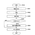
Fig. 6 is illustrated in the detailed flow chart of the recording processing among the S314 of Fig. 3.System, control circuit 50, use storage control circuit 22 and use image processing circuit 20 as required, read the view data that is written to memory 30, carry out pixel rate in length and breadth with capturing element by the pixel prosization processing of 1: 1 interpolation after (S401), the view data of handling is written to memory 30 with being through with.
And, read the view data that is written to memory 30, carry out the image Compression corresponding (S402) by compression/expansion circuit 32 with the setting pattern.System, control circuit 50 will be stored in the internal storage of system, control circuit 50 in S142 or the shooting date of memory 52 appends to (S406) on the image header.System, control circuit 50 judgements are stored in the internal storage of system, control circuit 50 or the date of memory 52 is added the state (S403) of mark, add mark if removed the date, just enter S405.
Add mark (being " unlatchings ") if set the date at S403, the title division of image additional be synthesized to image in the relevant information (date interpolation information) of date and time information (S404).The detailed content that appends to the date interpolation information of this image header will use Fig. 7 to be described below.Via interface 90 or 94, connector 92 or 96, the view data of compression is written to the recording medium 200 or 210 (S405) of storage card, Compact Flash (registered trade mark) card etc. at last.If be through with to the writing of recording medium, with regard to end record handling procedure S134.
The detailed expression of Fig. 7 A appends to the date interpolation information of the title of the image that the target date adds in the S404 of Fig. 6.Date interpolation information is to be used to discern the information of whether adding on the synthetic date of image, has: the information (positional information) of the target date position on the date on the image of adding such information and expression target date when adding on image whether.As whether adding such information, has date interpolation mark 301 in the image target date.Date adds mark 301 and gets these 2 values of true or false.If true, be illustrated in target date interpolation on the image, if false, be illustrated in image and do not have the target date to add, the content of coordinate information 302~305 does not just have meaning.
The information of the position on the date on the image when adding as the expression target date has following 4.Upper left x coordinate 302 of date is illustrated in the x coordinate on the image in the upper left corner of date Adding Area 306, and upper left y coordinate 303 of date is illustrated in the y coordinate on the image in the upper left corner of date Adding Area 306.Date bottom right x coordinate 304 is illustrated in the x coordinate on the image in the lower right corner of date Adding Area 306, and date bottom right y coordinate 305 is illustrated in the y coordinate on the image in the lower right corner of date Adding Area 306.
One of each coordinate position of expression for example shown in Fig. 7 B in view data.Here, the xy coordinate system is set as x axle, 309 directions 308 directions with 307 as initial point as the y axle.
With reference to Fig. 8~Figure 12, the action the when print processing of the image processing apparatus corresponding with present embodiment 100 is described.Image processing apparatus 100 directly is connected with printing equipment 600 via connector, communicates by utilizing telecommunication circuit 110 and printing equipment 600, can be by the image of printing equipment 600 print records in recording medium 200 and 210.
Fig. 8 be expression when connecting the image processing apparatus 100 of present embodiment and printing equipment 600 print images, with a routine corresponding flow chart in the processing of image processing apparatus 100 sides.Image processing apparatus 100 is connected with printing equipment 600 by using special-purpose cable, and printing model is transferred in communicating by letter of beginning and printing equipment 600.Under printing model, the image that is recorded in recording medium 200 and 210 can be presented at image displaying part 28, print the image in showing.
At first, based on the operation of the predetermined button of user's operating portion 70, on one side in turn displayed record at the image of recording medium 200 and 210, the selection (S501) of the image of acceptance printing on one side.
Under the state that has shown the image of printing, judge whether to accept print setting and begin operation (S502), when having accepted print setting and begin to move (is "Yes" at S502), print initial setting (S503), the print setting picture of Figure 11 is presented at image displaying part 28 (S504).
Use Fig. 9 that the details of printing initial setting (S503) is described here.In printing initial setting (S503), at first, default setting during as printing, read out in the set point of printing last time when printing the last time that is kept at when finishing in the nonvolatile memory 56, set the print setting (S601) of print conditions such as picture setting, paper setting, border setting.
Below, with reference to the interpolation of the date in the title of the image that shows information, judge whether synthetic date and time information (S602) in image.Here, when the interpolation of the date in date interpolation information sign 301 is " vacation ", because in not target date interpolation of image, so even handle date and time information according to the setting of printing equipment 600 sides, date and time information can dually not write yet.Therefore, as predetermined set value, the set point (S603) when printing the last time that is kept in the nonvolatile memory 56 is set on former state ground, finishes to print initial setting (S503).
On the other hand, adding sign 301 when the date be true time, because target date interpolation in image, so if the processing of synthesizing date and time information in printing equipment 600 sides, then date and time information will dually write.Therefore, be kept at the setting when printing last time in the nonvolatile memory 56 no matter be in " unlatchings ", " closing " which, all the day settings printed of this are set to " unlatchings " (S604), end printing initial setting (S503).
Like this, according to the present invention, when reference record when carrying out printing adds information on the date of image header, judged when the target date adds in image, be " unlatching " by the date print setting of establishing in printing equipment 600 sides as print conditions, be suppressed at the synthetic processing of the date and time information of printing equipment 600, can prevent that dual printing from writing the date of image and the date of adding at printing equipment 600.
When printing initial setting (S503) end, print setting picture shown in Figure 11 is presented at image displaying part (S504).Under this show state, judge whether to print to set and change (S505).Particularly, judge whether to have accepted the selection that form button 401 on the print setting picture of Figure 11 and number are set box 402 by operating portion 70.The result of this judgement, for example, when being judged as the selection that has received style button 401 (is "Yes" at S505), except picture shown in Figure 11, the change picture is set in the picture setting, paper setting, border setting etc. that also show other pictures, sets change (S506) by the operation acceptance of operating portion 70.In addition, when having selected number to set box 402 by operating portion 70 (is "Yes" at S505), the change (S506) of accepting to print number.If the print setting of S506 finishes, then enter S507.On the other hand, do not accept by operating portion 70 carry out to the selection of button 401 and button 402 action the time, just transfer to S507.
At S507, judge whether to carry out the side cut of image.The so-called side cut is used to set the processing of print area exactly.Usually, though, when only thinking the part zone of print image, can this zone be set at print area by cutting edge in print image integral body.Particularly, by operating portion 70, judged whether to select the side cut button 403 on the print setting picture of Figure 11.When having selected side cut button 403 (is "Yes" at S507), showing cuts edge sets picture, overlapping demonstration side cut frame 501 on the image of selecting as shown in Figure 12.Moving and big or small change of this side cut frame 501 can be accepted by operating portion 70, sets print area (S508).Here the print area of She Dinging is determined the upper left x coordinate 502 of side cut frame 501, upper left y coordinate 503, bottom right x coordinate 504, bottom right y coordinate 505 to view data.
On the other hand, when non-selected side cut button 403, transfer to S511, judge whether end setup.
After the setting at the S508 print area finished, the date interpolation information with reference in the title of the image that shows at image displaying part 28 judged whether synthetic date and time information (S509) in image information.Because if it is false that the date in the date interpolation information is added sign 301, then not target date interpolation on image, so, enter S511.
On the other hand, be true if the date is added sign 301, then add in the image target date.At this moment, add part,, reset the date (S501) so carry out whether being necessary to carry out the judgement that the date prints in printing equipment 600 sides because might eliminate the date by side cut.
Use Figure 10 that the details of date printing judgement (S501) is described.In print judging on the date, be attached to date in the image header according to expression and add the information of the date position on the image of information and the positional information of side cut frame, carry out in print area the date and add the judgement of whether finishing.
Particularly, at first relatively the cut edge upper left x coordinate 502 of frame 501 and the upper left x coordinate 302 (S701) of date Adding Area 306.If the upper left x coordinate of side cut frame 501 502 is more upper left x coordinate 302 big (is "No" at S701) than the date, then regard in print area not the target date as and add, enter S706.
If the upper left x coordinate of side cut frame 501 502 is more upper left x coordinate 302 little (is "Yes" at S701) than the date, then proceed the to cut edge comparison (S702) of upper left y coordinate 503 and upper left y coordinate 303 of date of frame 501, if the upper left y coordinate of side cut frame 501 503 is more upper left y coordinate 303 big (is "No" at S702) than the date, then regard not target date interpolation in print area as, enter S706.
If the upper left y coordinate of side cut frame 501 503 is more upper left y coordinate 303 little (is "Yes" at S702) than the date, then proceed the to cut edge comparison (S703) of bottom right x coordinate 504 and date bottom right x coordinate 304 of frame 501, if the bottom right x coordinate 504 of side cut frame 501 is than date bottom right x coordinate 304 little (is "No" at S703), then regard not target date interpolation in print area as, enter S706.
If the bottom right x coordinate 504 of side cut frame 501 is than date bottom right x coordinate 304 big (is "Yes" at S703), then proceed the to cut edge comparison (S704) of bottom right y coordinate 505 and date bottom right y coordinate 305 of frame 501, if the bottom right y coordinate 505 of side cut frame 501 is than date bottom right y coordinate 305 little (is "No" at S704), then regard not target date interpolation in print area as, enter S706.
If the bottom right y coordinate 505 of side cut frame 501 is than date bottom right y coordinate 305 big (is "Yes" at S704), then regarding in print area the date as adds and finishes, make at S604 be set at " cutting " day settings also for " cutting " (S705), the Close Date print to be judged (S510).
On the other hand, when the target date does not add in the print area that is judged as after having carried out cutting edge, according to the day settings that are set at " cutting " at S604, reset and be kept at nonvolatile memory 56, promptly, set point when print predefined last time (misspecification value) (S706), the Close Date print to be judged (S510).
Like this, according to the present invention, by carrying out the date interpolation information of cutting edge and being recorded in image header when printing when reference, when adding in the print area target date, make the date print setting be " cutting ", even in the side cut image, also be suppressed at date and time information synthetic of printing equipment 600, prevent on one side and will write the date of image and the dual printing of date that adds at printing equipment 600, when having write the date and time information of image by the deletion of cutting edge, day settings are turned back to the misspecification value on one side, can print at the synthetic date and time information of printing equipment 600 1 sides as required.Therefore, even when cutting edge frame, on one side also can prevent the dual printing on date, Yi Bian really additional date and time information.
If whole print settings is finished, judge whether end setup (S511).If heavily print setting (being " unlatching ") at S511, turn back to S505, accept to set change.
Then, judge whether to print at S512.By operating portion 70, judge whether to select the print button 405 on the print setting picture of Figure 11, when print button 405 is selected (is " execution " at S512), generates and be sent to the print data (S513) of using the printing equipment 600 that dedicated program is connected with image processing apparatus 100.
On the one hand, by operating portion 70, when cancel button on the print setting picture of Figure 11 404 is selected (is " cancellation " at S12), just turn back to S501, the acceptance pattern picture is selected.
When the generation in the print data of S315 finishes, the print data that generates is sent to printing equipment 600 (S514).This print data, as the operation that comprises as the print setting content of the print conditions of accepting, transmits to printing equipment 600 in image processing apparatus 100 except the view data of print object.Having received by printing equipment 600 sides of the operation that transmits from image processing apparatus 100, print, image processing apparatus 100 turns back to S501, and the acceptance pattern picture is selected.
In the above-described embodiment, image processing apparatus 100 directly is connected via plug 112 with printing equipment 600, by communication, the image that is recorded in recording medium 200 and 210 is printed from printing equipment 600 by telecommunication circuit 110.Structure of the present invention is not limited to image processing apparatus 100 and printing equipment 600 as individual design, also can constitute printing equipments 600 in that image processing apparatus 100 is whole, and system, control circuit 50 is also controlled printing equipment.
At this moment, in flow chart shown in Figure 8, print data in S514 transmits to handle replaces print processing, and the print processing corresponding with print setting content that sets in step before this and day settings is implemented.Therefore, when day settings are " unlatching ", do not carry out the writing of date and time information of printing equipment 600 sides, according to predetermined (for example last time) setting content, whether control carries out the interpolation of date and time information when " mistake ".
Further, make it have the such formation of printing function, also can realize to prevent and to add the date of image and by the printing equipment 600 of the additional dual printing of date of printing function by not making image processing apparatus 100 have shoot function.
At this moment, in printing equipment 600 1 sides, the image for being obtained by information acquisition device 606 can carry out processing as shown in Figure 8.Promptly, for adding the image of information on the additional date of title, the content of adding information based on the date judges whether at the synthetic date and time information of image, judging when image synthesizes date and time information, be suppressed at date and time information synthetic of printing equipment 600 sides, judging when image does not synthesize date and time information,, determine whether to carry out the interpolation processing of date and time information according to the misspecification of printing equipment 600.
According to above-mentioned the present invention, can when printing the image of taking, prevent that date and time information is by dual printing.
Because under the condition that does not break away from the spirit and scope of the present invention, can obtain the bigger many execution modes of notable difference of the present invention, so, be appreciated that to the invention is not restricted to these specific execution modes, unless in accompanying Claim, limited.
Claims (28)
1. an image processing apparatus is connected with printing equipment, and the above-mentioned printing equipment of may command is printed captured image, comprising:
Camera head is used for photographic images;
Set receiving device, the date and time information of having accepted whether will carry out to take is synthesized to the setting by the captured image of above-mentioned camera head;
Synthesizer, the setting based on above-mentioned setting receiving device is accepted is synthesized to above-mentioned date and time information by the captured image of above-mentioned camera head;
The identifying information generating apparatus, when date information has been synthesized to above-mentioned captured image, based on the above-mentioned setting of accepting, generate the identifying information of the print conditions be used to limit above-mentioned printing equipment, the identifying information that is generated is appended in the title of above-mentioned captured image; And
Conveyer will have the image of the title that has added above-mentioned identifying information, transmit to above-mentioned printing equipment.
2. image processing apparatus according to claim 1 is characterized in that:
In above-mentioned identifying information, be included in the positional information of synthetic above-mentioned date and time information in the above-mentioned image.
3. image processing apparatus according to claim 1 and 2 is characterized in that, also comprises:
The 1st judgment means based on above-mentioned identifying information, judges whether to have synthesized above-mentioned date and time information on above-mentioned image; And
The print conditions setting device when being judged as above-mentioned date and time information when being synthesized to above-mentioned image in above-mentioned the 1st judgment means, is set print conditions, makes synthetic to above-mentioned image that suppresses the above-mentioned date and time information in the above-mentioned printing equipment;
Above-mentioned conveyer transmits above-mentioned image and the above-mentioned print conditions that sets.
4. image processing apparatus according to claim 1 and 2 also comprises:
The 1st judgment means based on above-mentioned identifying information, judges whether to have synthesized above-mentioned date and time information on above-mentioned image; And
The print conditions setting device when being judged as above-mentioned date and time information when not being synthesized to above-mentioned image in above-mentioned the 1st judgment means, is synthesized to above-mentioned date and time information the predetermined print conditions of above-mentioned image setting about whether in above-mentioned printing equipment;
Above-mentioned conveyer transmits above-mentioned image and the above-mentioned print conditions that sets.
5. image processing apparatus according to claim 2 is characterized in that, also comprises:
The print area setting device is accepted the setting of the print area of above-mentioned image; With
The 2nd judgment means based on above-mentioned print area that sets and above-mentioned positional information, judges whether above-mentioned date and time information is present in the above-mentioned print area that sets;
When being judged as above-mentioned date and time information when being present in the above-mentioned print area that sets in above-mentioned the 2nd judgment means, above-mentioned print conditions setting device is set print conditions, makes synthetic to above-mentioned image that suppresses the above-mentioned date and time information in the above-mentioned printing equipment.
6. image processing apparatus according to claim 2 is characterized in that, also comprises:
The print area setting device is accepted the setting of the print area of above-mentioned image; With
The 2nd judgment means based on above-mentioned print area that sets and above-mentioned positional information, judges whether above-mentioned date and time information is present in the above-mentioned print area that sets;
When in the 2nd above-mentioned judgment means, being judged as above-mentioned date and time information when not being present in the above-mentioned print area that sets, whether above-mentioned print conditions setting device about carrying out the predefined print conditions of synthetic setting to above-mentioned image of the above-mentioned date and time information in the above-mentioned printing equipment.
7. the image processing apparatus of a printable captured image comprises:
Camera head is used for photographic images;
Set receiving device, the date and time information of having accepted whether will carry out to take is synthesized to the setting by the captured image of above-mentioned camera head;
Synthesizer, the setting based on above-mentioned setting receiving device is accepted is synthesized to above-mentioned date and time information by the captured image of above-mentioned camera head;
The identifying information generating apparatus when date information has been synthesized on the above-mentioned captured image, generates the identifying information that is used to limit print conditions based on the above-mentioned setting accepted, the identifying information that is generated is appended in the title of above-mentioned captured image; And
Printing equipment, print image.
8. image processing apparatus according to claim 7 is characterized in that:
In above-mentioned identifying information, be included in the positional information of synthetic above-mentioned date and time information in the above-mentioned image.
9. according to claim 7 or 8 described image processing apparatus, it is characterized in that:
Above-mentioned printing equipment also has
The 1st judgment means based on above-mentioned identifying information, judges whether to have synthesized above-mentioned date and time information on above-mentioned image;
When in above-mentioned the 1st judgment means, being judged as above-mentioned date and time information when being synthesized to above-mentioned image, in the printing of above-mentioned image, suppress synthetic to above-mentioned image of above-mentioned date and time information.
10. according to claim 7 or 8 described image processing apparatus, it is characterized in that:
Above-mentioned printing equipment also has
The 1st judgment means based on above-mentioned identifying information, judges whether to have synthesized above-mentioned date and time information on above-mentioned image;
When in above-mentioned the 1st judgment means, being judged as above-mentioned date and time information when not being synthesized to above-mentioned image,, carry out the printing of above-mentioned image according to predetermined print conditions about whether above-mentioned date and time information being synthesized to above-mentioned image.
11. image processing apparatus according to claim 8 is characterized in that, also comprises:
The print area setting device is accepted the setting of the print area of above-mentioned image; With
The 2nd judgment means based on above-mentioned print area that sets and above-mentioned positional information, judges whether above-mentioned date and time information is present in the above-mentioned print area that sets;
Above-mentioned printing equipment when being judged as that above-mentioned date and time information is present in the above-mentioned print area that sets in above-mentioned the 2nd judgment means, in the printing of above-mentioned image, suppresses synthetic to above-mentioned image of above-mentioned date and time information.
12. image processing apparatus according to claim 8 is characterized in that, also comprises:
The print area setting device is accepted the setting of the print area of above-mentioned image; With
The 2nd judgment means based on above-mentioned print area that sets and above-mentioned positional information, judges whether above-mentioned date and time information is present in the above-mentioned print area that sets;
Above-mentioned printing equipment, when being judged as that above-mentioned date and time information is not present in the above-mentioned print area that sets in the 2nd judgment means, about whether carrying out synthetic to above-mentioned image of above-mentioned date and time information, carry out the printing of above-mentioned image according to predefined print conditions.
13. the printing equipment of a printable image comprises:
Judgment means judges whether the date and time information of the shooting of having carried out above-mentioned image is synthesized to above-mentioned image;
The print conditions setting device when being judged as above-mentioned date and time information when being synthesized to above-mentioned image in above-mentioned judgment means, is set print conditions, makes synthetic to above-mentioned image that suppresses the above-mentioned date and time information in the above-mentioned printing equipment; And
Printing equipment prints based on the above-mentioned print conditions that sets.
14. printing equipment according to claim 13 is characterized in that:
In the title of above-mentioned image, add and be used to discern the identifying information that whether on above-mentioned image, has synthesized date and time information;
Above-mentioned judgment means is carried out above-mentioned judgement based on above-mentioned identifying information.
15. one kind is connected with printing equipment, the above-mentioned printing equipment of may command is printed the image processing apparatus control method of captured image, comprising:
Take step, be used for photographic images;
Step is accepted in setting, and the date and time information of having accepted whether will carry out to take is synthesized to the setting by the captured image of above-mentioned shooting step;
Synthesis step is accepted the setting that step is accepted based on above-mentioned setting, and above-mentioned date and time information is synthesized to by the captured image of above-mentioned shooting step;
Identifying information generates step, when date information has been synthesized to above-mentioned captured image, based on the above-mentioned setting of accepting, generate the identifying information of the print conditions be used to limit above-mentioned printing equipment, the identifying information that is generated is appended in the title of above-mentioned captured image; And
Transfer step will have the image of the title that has added above-mentioned identifying information, transmit to above-mentioned printing equipment.
16. image processing apparatus control method according to claim 15 is characterized in that:
In above-mentioned identifying information, be included in the positional information of synthetic above-mentioned date and time information in the above-mentioned image.
17. according to claim 15 or 16 described image processing apparatus control method, it is characterized in that, also comprise:
The 1st determining step based on above-mentioned identifying information, judges whether to have synthesized above-mentioned date and time information on above-mentioned image; And
Print conditions is set step, when being judged as above-mentioned date and time information when being synthesized to above-mentioned image in above-mentioned the 1st determining step, sets print conditions, makes synthetic to above-mentioned image that suppresses the above-mentioned date and time information in the above-mentioned printing equipment;
In above-mentioned transfer step, transmit above-mentioned image and the above-mentioned print conditions that sets.
18., also comprise according to claim 15 or 16 described image processing apparatus control method:
The 1st determining step based on above-mentioned identifying information, judges whether to have synthesized above-mentioned date and time information on above-mentioned image; And
Set step at print conditions, when in above-mentioned the 1st determining step, being judged as above-mentioned date and time information when not being synthesized to above-mentioned image, in above-mentioned printing equipment, above-mentioned date and time information is synthesized to the predetermined print conditions of above-mentioned image setting about whether;
Above-mentioned transfer step transmits above-mentioned image and the above-mentioned print conditions that sets.
19. image processing apparatus control method according to claim 16 is characterized in that, also comprises:
Print area is set step, accepts the setting of the print area of above-mentioned image; With
The 2nd determining step based on above-mentioned print area that sets and above-mentioned positional information, judges whether above-mentioned date and time information is present in the above-mentioned print area that sets;
When being judged as above-mentioned date and time information when being present in the above-mentioned print area that sets in above-mentioned the 2nd determining step, above-mentioned print conditions is set step and is set print conditions, makes synthetic to above-mentioned image that suppresses the above-mentioned date and time information in the above-mentioned printing equipment.
20. image processing apparatus control method according to claim 16 is characterized in that, also comprises:
Print area is set step, accepts the setting of the print area of above-mentioned image; With
The 2nd determining step based on above-mentioned print area that sets and above-mentioned positional information, judges whether above-mentioned date and time information is present in the above-mentioned print area that sets;
When in the 2nd above-mentioned determining step, being judged as above-mentioned date and time information when not being present in the above-mentioned print area that sets, above-mentioned print conditions is set step, about whether carry out in the above-mentioned printing equipment above-mentioned date and time information to the predetermined print conditions of the synthetic setting of above-mentioned image.
21. the image processing apparatus control method of a printable captured image comprises:
Take step, be used for photographic images;
Step is accepted in setting, and the date and time information of having accepted whether will carry out to take is synthesized to the setting by the captured image of above-mentioned shooting step;
Synthesis step is accepted the setting that step is accepted based on above-mentioned setting, and above-mentioned date and time information is synthesized to by the captured image of above-mentioned shooting step;
Identifying information generates step, when date information has been synthesized on the above-mentioned captured image, generates the identifying information that is used to limit print conditions based on the above-mentioned setting of accepting, and the identifying information that is generated is appended in the title of above-mentioned captured image; And
Printing step is printed the image with the title that has added above-mentioned identifying information.
22. image processing apparatus control method according to claim 21 is characterized in that:
In above-mentioned identifying information, be included in the positional information of synthetic above-mentioned date and time information in the above-mentioned image.
23., it is characterized in that according to claim 21 or 22 described image processing apparatus control method:
Above-mentioned printing step also has
The 1st determining step based on above-mentioned identifying information, judges whether to have synthesized above-mentioned date and time information on above-mentioned image;
When in above-mentioned the 1st determining step, being judged as above-mentioned date and time information when being synthesized to above-mentioned image, in the printing of above-mentioned image, suppress synthetic to above-mentioned image of above-mentioned date and time information.
24., it is characterized in that according to claim 21 or 22 described image processing apparatus control method:
Above-mentioned printing step also has
The 1st determining step based on above-mentioned identifying information, judges whether to have synthesized above-mentioned date and time information on above-mentioned image;
When in above-mentioned the 1st determining step, being judged as above-mentioned date and time information when not being synthesized to above-mentioned image,, carry out the printing of above-mentioned image according to predetermined print conditions about whether above-mentioned date and time information being synthesized to above-mentioned image.
25. image processing apparatus control method according to claim 22 is characterized in that, also comprises:
Print area is set step, accepts the setting of the print area of above-mentioned image; With
The 2nd determining step based on above-mentioned print area that sets and above-mentioned positional information, judges whether above-mentioned date and time information is present in the above-mentioned print area that sets;
In above-mentioned printing step, when being judged as that above-mentioned date and time information is present in the above-mentioned print area that sets in above-mentioned the 2nd determining step, in the printing of above-mentioned image, suppress synthetic to above-mentioned image of above-mentioned date and time information.
26. image processing apparatus control method according to claim 22 is characterized in that, also comprises:
Print area is set step, accepts the setting of the print area of above-mentioned image; And
The 2nd determining step based on above-mentioned print area that sets and above-mentioned positional information, judges whether above-mentioned date and time information is present in the above-mentioned print area that sets;
In above-mentioned printing step, when being judged as that above-mentioned date and time information is not present in the above-mentioned print area that sets in the 2nd determining step, about whether carrying out synthetic to above-mentioned image of above-mentioned date and time information, carry out the printing of above-mentioned image according to predefined print conditions.
27. the control method of the printing equipment of a printable image comprises:
Determining step judges whether the date and time information of the shooting of having carried out above-mentioned image is synthesized to above-mentioned image;
Print conditions is set step, when being judged as above-mentioned date and time information when being synthesized to above-mentioned image in above-mentioned determining step, sets print conditions, makes synthetic to above-mentioned image that suppresses the above-mentioned date and time information in the above-mentioned printing equipment; And
Printing step prints based on the above-mentioned print conditions that sets.
28. the control method of printing equipment according to claim 27 is characterized in that:
In the title of above-mentioned image, add and be used to discern the identifying information that whether on above-mentioned image, has synthesized date and time information;
In above-mentioned determining step, carry out above-mentioned judgement based on above-mentioned identifying information.
Applications Claiming Priority (2)
| Application Number | Priority Date | Filing Date | Title |
|---|---|---|---|
| JP2004031400A JP2005223758A (en) | 2004-02-06 | 2004-02-06 | Image processing apparatus, control method thereof, computer program, and recording medium |
| JP031400/2004 | 2004-02-06 |
Publications (2)
| Publication Number | Publication Date |
|---|---|
| CN1652595A CN1652595A (en) | 2005-08-10 |
| CN100435575C true CN100435575C (en) | 2008-11-19 |
Family
ID=34824170
Family Applications (1)
| Application Number | Title | Priority Date | Filing Date |
|---|---|---|---|
| CNB2005100075329A Expired - Fee Related CN100435575C (en) | 2004-02-06 | 2005-02-05 | Image processing apparatus and control method |
Country Status (3)
| Country | Link |
|---|---|
| US (1) | US7710467B2 (en) |
| JP (1) | JP2005223758A (en) |
| CN (1) | CN100435575C (en) |
Families Citing this family (13)
| Publication number | Priority date | Publication date | Assignee | Title |
|---|---|---|---|---|
| KR20060082188A (en) * | 2005-01-11 | 2006-07-18 | 삼성테크윈 주식회사 | Method of controlling digital image processing apparatus for accurate printing, and digital image processing apparatus adopting the method |
| JP2006261727A (en) * | 2005-03-15 | 2006-09-28 | Seiko Epson Corp | Information display device |
| JP2006256275A (en) * | 2005-03-18 | 2006-09-28 | Canon Inc | Apparatus and image forming apparatus |
| JP4546299B2 (en) * | 2005-03-18 | 2010-09-15 | キヤノン株式会社 | Image forming apparatus |
| JP2006270868A (en) * | 2005-03-25 | 2006-10-05 | Olympus Imaging Corp | Imaging apparatus and image recording method |
| JP4315161B2 (en) * | 2006-02-16 | 2009-08-19 | 村田機械株式会社 | Image reader with time authentication request function |
| JP4746473B2 (en) * | 2006-04-27 | 2011-08-10 | 辰巳電子工業株式会社 | Automatic photo creation device, automatic photo creation method, and photo service system using the automatic photo creation device |
| US9131140B2 (en) | 2007-08-10 | 2015-09-08 | Canon Kabushiki Kaisha | Image pickup apparatus and image pickup method |
| JP5014241B2 (en) * | 2007-08-10 | 2012-08-29 | キヤノン株式会社 | Imaging apparatus and control method thereof |
| JP4593651B2 (en) * | 2008-05-30 | 2010-12-08 | キヤノンItソリューションズ株式会社 | Information processing apparatus, information processing system, information processing apparatus control method, and program |
| JP4591552B2 (en) * | 2008-06-10 | 2010-12-01 | コニカミノルタビジネステクノロジーズ株式会社 | Image forming apparatus, image forming method, and image forming program |
| JP2019205111A (en) * | 2018-05-25 | 2019-11-28 | セイコーエプソン株式会社 | Image processing apparatus, robot, and robot system |
| CN113574854B (en) * | 2019-03-15 | 2023-06-06 | 富士胶片株式会社 | Digital video camera with printer and system for digital video camera with printer |
Citations (4)
| Publication number | Priority date | Publication date | Assignee | Title |
|---|---|---|---|---|
| JPH11133522A (en) * | 1997-10-28 | 1999-05-21 | Noritsu Koki Co Ltd | Photographic processing device |
| EP1186429A2 (en) * | 2000-09-12 | 2002-03-13 | Canon Kabushiki Kaisha | Media pack, printer, and camera with printer |
| JP2003057739A (en) * | 2001-08-10 | 2003-02-26 | Noritsu Koki Co Ltd | Automatic photographing device |
| US20030112344A1 (en) * | 2001-12-19 | 2003-06-19 | Fuji Photo Film Co., Ltd. | Digital still camera |
Family Cites Families (21)
| Publication number | Priority date | Publication date | Assignee | Title |
|---|---|---|---|---|
| US6351321B1 (en) * | 1995-02-14 | 2002-02-26 | Eastman Kodak Company | Data scanning and conversion system for photographic image reproduction |
| US5847836A (en) * | 1995-08-29 | 1998-12-08 | Canon Kabushiki Kaisha | Printer-built-in image-sensing apparatus and using strobe-light means electric-consumption control method thereof |
| JPH09133976A (en) * | 1995-11-08 | 1997-05-20 | Konica Corp | Photographic film having information recording layer and camera loaded with the film |
| US5633678A (en) * | 1995-12-20 | 1997-05-27 | Eastman Kodak Company | Electronic still camera for capturing and categorizing images |
| JP3832089B2 (en) | 1997-05-26 | 2006-10-11 | セイコーエプソン株式会社 | Digital camera and printing system |
| JPH1188742A (en) * | 1997-09-09 | 1999-03-30 | Olympus Optical Co Ltd | Electronic camera |
| JP4101910B2 (en) * | 1997-09-09 | 2008-06-18 | オリンパス株式会社 | Electronic camera |
| US6275260B1 (en) * | 1997-09-17 | 2001-08-14 | Flashpoint Technology, Inc. | Positioning stamps in images captured with an image capture unit |
| US6535298B2 (en) * | 1998-10-15 | 2003-03-18 | Hewlett-Packard Company | Storing and retrieving digital camera images via a user-completed proof sheet |
| US6956671B2 (en) * | 1998-10-15 | 2005-10-18 | Hewlett-Packard Development Company, L.P. | Specifying image file processing operations via device controls and a user-completed proof sheet |
| JP2000190579A (en) | 1998-12-28 | 2000-07-11 | Canon Inc | Photoprinter |
| US6512856B1 (en) * | 1999-07-27 | 2003-01-28 | Hewlett-Packard Company | System and method for information stamping a digitized image |
| JP2001103269A (en) * | 1999-09-28 | 2001-04-13 | Olympus Optical Co Ltd | Printer and electronic camera apparatus |
| JP4009926B2 (en) * | 2000-06-30 | 2007-11-21 | 富士フイルム株式会社 | Image output method and apparatus |
| EP1213604B1 (en) * | 2000-12-08 | 2008-01-23 | Konica Corporation | Photographic processing and printing method |
| JP2002314931A (en) * | 2001-04-10 | 2002-10-25 | Olympus Optical Co Ltd | Electronic camera |
| JP4460798B2 (en) * | 2001-06-07 | 2010-05-12 | オリンパス株式会社 | Image processing apparatus, image processing method, and electronic camera |
| JP3884942B2 (en) * | 2001-10-31 | 2007-02-21 | キヤノン株式会社 | IMAGING DEVICE, SYSTEM HAVING IMAGING DEVICE AND RECORDING DEVICE AND CONTROL METHOD THEREOF |
| JP2003246119A (en) | 2002-02-22 | 2003-09-02 | Canon Inc | Image recorder and its controlling method |
| US7014374B2 (en) * | 2002-09-25 | 2006-03-21 | Seiko Epson Corporation | Printing apparatus and printing method for performing pre-communication with an external device |
| JP4292820B2 (en) * | 2003-02-14 | 2009-07-08 | 株式会社ニコン | Electronic camera |
-
2004
- 2004-02-06 JP JP2004031400A patent/JP2005223758A/en active Pending
-
2005
- 2005-01-28 US US11/044,256 patent/US7710467B2/en not_active Expired - Fee Related
- 2005-02-05 CN CNB2005100075329A patent/CN100435575C/en not_active Expired - Fee Related
Patent Citations (5)
| Publication number | Priority date | Publication date | Assignee | Title |
|---|---|---|---|---|
| JPH11133522A (en) * | 1997-10-28 | 1999-05-21 | Noritsu Koki Co Ltd | Photographic processing device |
| EP1186429A2 (en) * | 2000-09-12 | 2002-03-13 | Canon Kabushiki Kaisha | Media pack, printer, and camera with printer |
| CN1347807A (en) * | 2000-09-12 | 2002-05-08 | 佳能株式会社 | Medium box, printer and camera attached with printer |
| JP2003057739A (en) * | 2001-08-10 | 2003-02-26 | Noritsu Koki Co Ltd | Automatic photographing device |
| US20030112344A1 (en) * | 2001-12-19 | 2003-06-19 | Fuji Photo Film Co., Ltd. | Digital still camera |
Also Published As
| Publication number | Publication date |
|---|---|
| JP2005223758A (en) | 2005-08-18 |
| US20050174597A1 (en) | 2005-08-11 |
| US7710467B2 (en) | 2010-05-04 |
| CN1652595A (en) | 2005-08-10 |
Similar Documents
| Publication | Publication Date | Title |
|---|---|---|
| CN100435575C (en) | Image processing apparatus and control method | |
| CN101364029B (en) | Image capturing apparatus and control method therefor | |
| CN100418357C (en) | Image processing apparatus, image processing method | |
| CN100531320C (en) | Image processing apparatus, method thereof, and image sensing apparatus | |
| CN101115113B (en) | Photographing apparatus and photographing method | |
| CN101631195B (en) | Image pickup device and control method thereof | |
| CN101904163B (en) | Image processing apparatus, method of controlling the same, and storage medium | |
| CN100414975C (en) | Imaging apparatus and control method therefor | |
| CN103957356A (en) | Electronic device, and image obtaining method of electronic device | |
| CN101150661B (en) | Image processing apparatus, image capture apparatus and control method therefor | |
| CN101494715B (en) | Image editing apparatus, image editing method | |
| CN102375323A (en) | Imaging system and image capturing apparatus | |
| CN1322347C (en) | Image pickup apparatus, control method thereof, control program thereof and storage medium | |
| JP2002064740A (en) | Electronic camera and remote control system for external device | |
| CN100473113C (en) | Image managing system | |
| JP2005150836A (en) | Photographing apparatus | |
| CN100529949C (en) | Photographic device | |
| CN100531305C (en) | Display changeover control in image sensing apparatus | |
| CN101252644B (en) | Image capturing device | |
| EP1628463A1 (en) | Electronic card for a digital camera | |
| CN100498929C (en) | Image display apparatus and image display method | |
| CN100413348C (en) | Image processing method and apparatus | |
| CN100362422C (en) | Image photographic device, image photographic method, program and recording medium | |
| CN100417192C (en) | Image sensing apparatus and control method therefor | |
| CN100593945C (en) | Image pickup apparatus, method of controlling the image pickup apparatus |
Legal Events
| Date | Code | Title | Description |
|---|---|---|---|
| C06 | Publication | ||
| PB01 | Publication | ||
| C10 | Entry into substantive examination | ||
| SE01 | Entry into force of request for substantive examination | ||
| C14 | Grant of patent or utility model | ||
| GR01 | Patent grant | ||
| CF01 | Termination of patent right due to non-payment of annual fee |
Granted publication date: 20081119 Termination date: 20210205 |
|
| CF01 | Termination of patent right due to non-payment of annual fee |