CN100435219C - Recording apparatus and recording method - Google Patents
Recording apparatus and recording method Download PDFInfo
- Publication number
- CN100435219C CN100435219C CNB2006100923144A CN200610092314A CN100435219C CN 100435219 C CN100435219 C CN 100435219C CN B2006100923144 A CNB2006100923144 A CN B2006100923144A CN 200610092314 A CN200610092314 A CN 200610092314A CN 100435219 C CN100435219 C CN 100435219C
- Authority
- CN
- China
- Prior art keywords
- recording
- data
- user data
- record
- recording layer
- Prior art date
- Legal status (The legal status is an assumption and is not a legal conclusion. Google has not performed a legal analysis and makes no representation as to the accuracy of the status listed.)
- Expired - Fee Related
Links
Images


Classifications
-
- G—PHYSICS
- G11—INFORMATION STORAGE
- G11B—INFORMATION STORAGE BASED ON RELATIVE MOVEMENT BETWEEN RECORD CARRIER AND TRANSDUCER
- G11B7/00—Recording or reproducing by optical means, e.g. recording using a thermal beam of optical radiation by modifying optical properties or the physical structure, reproducing using an optical beam at lower power by sensing optical properties; Record carriers therefor
- G11B7/007—Arrangement of the information on the record carrier, e.g. form of tracks, actual track shape, e.g. wobbled, or cross-section, e.g. v-shaped; Sequential information structures, e.g. sectoring or header formats within a track
- G11B7/00736—Auxiliary data, e.g. lead-in, lead-out, Power Calibration Area [PCA], Burst Cutting Area [BCA], control information
-
- G—PHYSICS
- G11—INFORMATION STORAGE
- G11B—INFORMATION STORAGE BASED ON RELATIVE MOVEMENT BETWEEN RECORD CARRIER AND TRANSDUCER
- G11B20/00—Signal processing not specific to the method of recording or reproducing; Circuits therefor
- G11B20/10—Digital recording or reproducing
-
- G—PHYSICS
- G11—INFORMATION STORAGE
- G11B—INFORMATION STORAGE BASED ON RELATIVE MOVEMENT BETWEEN RECORD CARRIER AND TRANSDUCER
- G11B20/00—Signal processing not specific to the method of recording or reproducing; Circuits therefor
- G11B20/10—Digital recording or reproducing
- G11B20/12—Formatting, e.g. arrangement of data block or words on the record carriers
- G11B20/1217—Formatting, e.g. arrangement of data block or words on the record carriers on discs
-
- G—PHYSICS
- G11—INFORMATION STORAGE
- G11B—INFORMATION STORAGE BASED ON RELATIVE MOVEMENT BETWEEN RECORD CARRIER AND TRANSDUCER
- G11B7/00—Recording or reproducing by optical means, e.g. recording using a thermal beam of optical radiation by modifying optical properties or the physical structure, reproducing using an optical beam at lower power by sensing optical properties; Record carriers therefor
- G11B7/004—Recording, reproducing or erasing methods; Read, write or erase circuits therefor
- G11B7/0045—Recording
-
- G—PHYSICS
- G11—INFORMATION STORAGE
- G11B—INFORMATION STORAGE BASED ON RELATIVE MOVEMENT BETWEEN RECORD CARRIER AND TRANSDUCER
- G11B7/00—Recording or reproducing by optical means, e.g. recording using a thermal beam of optical radiation by modifying optical properties or the physical structure, reproducing using an optical beam at lower power by sensing optical properties; Record carriers therefor
- G11B7/24—Record carriers characterised by shape, structure or physical properties, or by the selection of the material
- G11B7/2403—Layers; Shape, structure or physical properties thereof
- G11B7/24035—Recording layers
- G11B7/24038—Multiple laminated recording layers
-
- G—PHYSICS
- G11—INFORMATION STORAGE
- G11B—INFORMATION STORAGE BASED ON RELATIVE MOVEMENT BETWEEN RECORD CARRIER AND TRANSDUCER
- G11B20/00—Signal processing not specific to the method of recording or reproducing; Circuits therefor
- G11B20/10—Digital recording or reproducing
- G11B20/12—Formatting, e.g. arrangement of data block or words on the record carriers
- G11B20/1217—Formatting, e.g. arrangement of data block or words on the record carriers on discs
- G11B2020/1218—Formatting, e.g. arrangement of data block or words on the record carriers on discs wherein the formatting concerns a specific area of the disc
- G11B2020/1228—Formatting, e.g. arrangement of data block or words on the record carriers on discs wherein the formatting concerns a specific area of the disc middle zone or outer guard area of a multilayer disc
-
- G—PHYSICS
- G11—INFORMATION STORAGE
- G11B—INFORMATION STORAGE BASED ON RELATIVE MOVEMENT BETWEEN RECORD CARRIER AND TRANSDUCER
- G11B20/00—Signal processing not specific to the method of recording or reproducing; Circuits therefor
- G11B20/10—Digital recording or reproducing
- G11B20/12—Formatting, e.g. arrangement of data block or words on the record carriers
- G11B20/1217—Formatting, e.g. arrangement of data block or words on the record carriers on discs
- G11B2020/1218—Formatting, e.g. arrangement of data block or words on the record carriers on discs wherein the formatting concerns a specific area of the disc
- G11B2020/1231—Formatting, e.g. arrangement of data block or words on the record carriers on discs wherein the formatting concerns a specific area of the disc lead-out area
-
- G—PHYSICS
- G11—INFORMATION STORAGE
- G11B—INFORMATION STORAGE BASED ON RELATIVE MOVEMENT BETWEEN RECORD CARRIER AND TRANSDUCER
- G11B20/00—Signal processing not specific to the method of recording or reproducing; Circuits therefor
- G11B20/10—Digital recording or reproducing
- G11B20/12—Formatting, e.g. arrangement of data block or words on the record carriers
- G11B2020/1264—Formatting, e.g. arrangement of data block or words on the record carriers wherein the formatting concerns a specific kind of data
- G11B2020/1288—Formatting by padding empty spaces with dummy data, e.g. writing zeroes or random data when de-icing optical discs
-
- G—PHYSICS
- G11—INFORMATION STORAGE
- G11B—INFORMATION STORAGE BASED ON RELATIVE MOVEMENT BETWEEN RECORD CARRIER AND TRANSDUCER
- G11B20/00—Signal processing not specific to the method of recording or reproducing; Circuits therefor
- G11B20/10—Digital recording or reproducing
- G11B20/12—Formatting, e.g. arrangement of data block or words on the record carriers
- G11B2020/1291—Formatting, e.g. arrangement of data block or words on the record carriers wherein the formatting serves a specific purpose
- G11B2020/1294—Increase of the access speed
- G11B2020/1297—Increase of the access speed wherein the focus is on the write access speed
-
- G—PHYSICS
- G11—INFORMATION STORAGE
- G11B—INFORMATION STORAGE BASED ON RELATIVE MOVEMENT BETWEEN RECORD CARRIER AND TRANSDUCER
- G11B2220/00—Record carriers by type
- G11B2220/20—Disc-shaped record carriers
- G11B2220/21—Disc-shaped record carriers characterised in that the disc is of read-only, rewritable, or recordable type
- G11B2220/215—Recordable discs
- G11B2220/216—Rewritable discs
-
- G—PHYSICS
- G11—INFORMATION STORAGE
- G11B—INFORMATION STORAGE BASED ON RELATIVE MOVEMENT BETWEEN RECORD CARRIER AND TRANSDUCER
- G11B2220/00—Record carriers by type
- G11B2220/20—Disc-shaped record carriers
- G11B2220/21—Disc-shaped record carriers characterised in that the disc is of read-only, rewritable, or recordable type
- G11B2220/215—Recordable discs
- G11B2220/218—Write-once discs
-
- G—PHYSICS
- G11—INFORMATION STORAGE
- G11B—INFORMATION STORAGE BASED ON RELATIVE MOVEMENT BETWEEN RECORD CARRIER AND TRANSDUCER
- G11B2220/00—Record carriers by type
- G11B2220/20—Disc-shaped record carriers
- G11B2220/23—Disc-shaped record carriers characterised in that the disc has a specific layer structure
- G11B2220/235—Multilayer discs, i.e. multiple recording layers accessed from the same side
-
- G—PHYSICS
- G11—INFORMATION STORAGE
- G11B—INFORMATION STORAGE BASED ON RELATIVE MOVEMENT BETWEEN RECORD CARRIER AND TRANSDUCER
- G11B2220/00—Record carriers by type
- G11B2220/20—Disc-shaped record carriers
- G11B2220/25—Disc-shaped record carriers characterised in that the disc is based on a specific recording technology
- G11B2220/2537—Optical discs
- G11B2220/2562—DVDs [digital versatile discs]; Digital video discs; MMCDs; HDCDs
- G11B2220/257—DVDs belonging to the plus family, i.e. +R, +RW, +VR
-
- G—PHYSICS
- G11—INFORMATION STORAGE
- G11B—INFORMATION STORAGE BASED ON RELATIVE MOVEMENT BETWEEN RECORD CARRIER AND TRANSDUCER
- G11B7/00—Recording or reproducing by optical means, e.g. recording using a thermal beam of optical radiation by modifying optical properties or the physical structure, reproducing using an optical beam at lower power by sensing optical properties; Record carriers therefor
- G11B7/004—Recording, reproducing or erasing methods; Read, write or erase circuits therefor
- G11B7/0045—Recording
- G11B7/00454—Recording involving phase-change effects
Abstract
A recording apparatus performs recording on an optical disc recording medium which has a plurality of recording layers and is capable of having data rewritten thereon. The recording apparatus includes recording means for performing data recording on each recording layer of the recording medium and recording controlling means for controlling the recording means so that, among the plurality of recording layers, recording of dummy data is performed preferentially starting from a recording layer intended for the final user data recording operation.
Description
(to the cross reference of related application)
The present invention comprises and the relevant theme of submitting in Jap.P. office on June 1st, 2005 of Japanese patent application JP2005-161429, quotes its full content as a reference at this.
Technical field
The present invention relates to be used for to have a plurality of recording layers and the pen recorder of executive logging on the optical disc recording medium of overwriting data thereon.The invention still further relates to the recording method that is used for pen recorder.
Background technology
Optical disc recording medium is a light recording information and from the known example of the optical recording media of its information reproduction thereon.
As the example of this recording medium, DVD (digital multi-purpose disk) is widely used.The type of the DVD that exists comprises: it on a reproduction pattern DVD-ROM of the form tracer signal of the pit that protrudes and boss combination, wherein only allow an executive logging and be DVD-RW or the DVD+RW that recording layer uses the DVD-R of dyestuff changing film or DVD+R and wherein allows overwriting data as recording layer use phase-change film thus.
In above DVD, more late than the DVD-RW that is the rewritable media type equally as the development time of the DVD+RW of rewritable media type.Therefore, compare with DVD-RW, DVD+RW has bigger user-operable.
For example, for DVD+RW, use can be shortened the configuration of disk formatting required time.
Rewritable disk such as the DVD+RW dish is configured to stand so-called format processing can be used in the reproduction pattern device.In this format was handled, the non-recorded part that is used for the data field of user data was full of the pseudo-data such as whole 0 data.
For the dish of some types, handle on whole dish, carrying out this format be used to guarantee with the compatibility of transcriber before the user data.On the contrary, the DVD+RW dish is configured to make can not have beginning user data record under the situation of disk formatting, and this can shorten the setup time of record.In this case, the disk formatting that is used for non-recorded part is configured to not carry out at driver and writes or carry out automatically during read operation (idle condition).Therefore, format is handled and is carried out on the backstage, can shorten period of reservation of number thus and improve operability.Above-mentioned this format technology is called as the backstage format.
For the DVD+RW dish, the format of whole dish is not to carry out immediately after dish loads.Therefore may have such a case, that is, only the dish that writes down the part of its data field with user data was not asked before the format of whole dish is finished.
When the formative indicator of this part by At time of eject, terminally in the zone that is recording user data add temporary derivation.This operation guarantees the compatibility with a reproduction pattern device.
Thus, the user data that provides leading-out zone to guarantee record in the data field reproduces in a reproduction pattern device.Because this leading-out zone is temporary, therefore, when dish is reloaded, by wiping leading-out zone, can restart the record of user data.
With reference to Fig. 9, Figure 10 A this backstage format for DVD+RW dish execution relevant with adding temporary derivation with Figure 10 B explanation.
Each figure in these accompanying drawings illustrates the regional structure of dish.As shown in the figure, Lead-In Area is positioned on the internal diameter of dish, is the data field that is used for the user data record that is positioned at the outside diameter of Lead-In Area then.
Referring now to Fig. 9, the example that has been recorded by data file among the figure illustrates the situation of dish.When this data file is recorded in dish when going up, data file probably with as shown in Figure 9 in the data field form of the user data block of interruption logging (UD) be recorded.Particularly under the situation that UDF (multi-purpose disk form) is used to coil, recording operation is implemented in such a way, that is, and and at the internal side diameter in the data field of adjacent Lead-In Area, as user data block UD 1 log file management information.In this operation, the data file of real data needn't be recorded in the zone with the region adjacent of log file management information.Therefore, being recorded in the user data block UD 1 on the internal diameter in data field and be recorded as probably as the user data UD 2 of real data has at interval betwixt.
Be interrupted in the situation of record in this data block, the data field comprises non-recorded part, and does not have leading-out zone.This make this dish not with a reproduction pattern device compatibility.
With reference to Figure 10 A, above-mentioned backstage format technology is described.In backstage format is handled, the order that is recorded according to user data, internal side diameter is carried out the record of pseudo-data successively the unit of booking situation piece BF to outside diameter from the data field.
Now, shown in Figure 10 A, suppose successively from the piece BF 1 that is positioned at the internal side diameter in data field and implement the backstages format to piece BF 5.Then, to carry out the record of data file with the similar mode of the situation shown in Fig. 9, in Fig. 9, user data block UD 1 and user data block UD 2 are recorded in the data field.
Because backstage format is implemented, therefore, this produces the situation shown in Figure 10 B, and wherein pseudo-data block is recorded in the zone between user data block UD 1 and the UD 2.In this case, when following when dish proposed with the request of a reproduction pattern device compatibility proposition dish ejection request, the outer diameter zone after user data block UD 2 is terminal promptly is provided with temporary derivation on the terminal position in user record zone in the data field.This operation helps coiling quick ejection.
Can find that from the above description the format of execution backstage can be eliminated or reduce when coiling and be write down pseudo-section data by At time of eject.Therefore this shortening is used to coil the period of reservation of number of ejection.
At present, introduced the type of the DVD+RW dish that one deck recording layer is only arranged.But, similar with medium such as other type of DVD-ROM dish and DVD-R or DVD+R dish, exploitation multilayer DVD+RW dish is attempted.
The open No.1999-167725 of Japanese unexamined patent discloses the technology that is used to provide the DVD-ROM dish with a plurality of recording layers.In the open No.1999-134799 of Japanese unexamined patent, discussed and on the CD-RW recording medium, carried out the formative technology in backstage.
Summary of the invention
Now, suppose multilayer DVD+RW dish is provided.Then, by use Figure 11 and Figure 12, the running program that explanation can be carried out when above-mentioned known backstage format technology being applied to multilayer DVD+RW dish.
Figure 11 illustrates the plot structure of the dish with a plurality of recording layers.In this manual, the explanation dish has the situation that two recording layers and so-called backlight path are used to coil.More specifically, for first recording layer (layer 0) that is arranged near a side of the object lens of pen recorder, from the internal side diameter to the outside diameter, carry out the record of user data successively.On the contrary, for being positioned at second recording layer away from a side of object lens (layer 1), from outside diameter to the internal side diameter executive logging.
When known backstage format technology is used for this dual layer discs, according to the order of user data record, the unit of piece BF, implement the record of pseudo-data successively from the internal side diameter of first recording layer shown in Figure 11.
Now, similar with the situation shown in Figure 10 A, suppose successively and to implement the backstage format from piece BF 1 to piece BF5, and user data piece UD 1 and user data block UD 2 then.
Final situation in the data field of coiling shown in Figure 12 A.Particularly, similar with the situation shown in Figure 10 B, the zone between user data block UD 1 and the user data block UD 2 is formatted.Therefore, when the request that dish proposed with a reproduction pattern device compatibility, do not need further first recording layer to be formatd.
Respond this request, the outside diameter in the layer to layer transition part adds interim mesozone as the protected location.
But because the dish in this example has a plurality of recording layers, therefore, for the dish compatibility with a reproduction pattern device is provided, it is unsafty that this interim mesozone is provided simply.In order to realize compatibility, in the zone of radial distance than the terminal near data field of the user data piece UD in first recording layer, any data all must be recorded in each recording layer.
More specifically, in this case, promise to eject request, in Figure 12 A, be illustrated as F new, be positioned at radial distance than the terminal near locational zone that is recorded in the user data block UD2 on first recording layer, pseudo-data also must be recorded on second recording layer.
Therefore, for the multilayer disc of carrying out pseudo-data recording from the internal side diameter of first recording layer successively, can use known backstage format technology.But, from above-mentioned example as can be seen, on the recording layer of the final entry operation that is intended for use to carry out user data, carry out in this case pseudo-data recording at the end of record segment.
In other words, when known backstage format technology was applied to multilayer disc, the format that is intended for use the recording layer of end user data recording operation was configured to be implemented at the end of record segment.Because be the format manipulation that the recording layer that is intended for use the user data final entry is carried out, this is the required time of increase dish ejection therefore.
In above-mentioned example, the situation that the backlight path is used to coil has been described.But, under the situation of using the directional light path, wherein in each recording layer along identical direction record data, similar problem appears in the known backstage format that meets user data record order in execution when handling.
In view of the foregoing, the present invention is proposed.The pen recorder that therefore, need have following configuration.
According to an aspect of the present invention, a kind of pen recorder is provided, be used for having a plurality of recording layers and executive logging on the optical disc recording medium of overwriting data thereon, this pen recorder comprises: recording-member, this recording-member are used for carrying out data recording on each recording layer of described recording medium; With the record controls parts, these record controls parts are used to control described recording-member, make in described a plurality of recording layers, preferentially begin to carry out the record of pseudo-data from the recording layer that is intended for use the end user data recording operation, wherein, described record controls parts are controlled described recording-member, make preferentially to begin to the record that is intended for use to carry out pseudo-data that described zone is arranged in the recording layer that is used for the end user data recording operation in the zone of preceding recording operation from the regional order that is intended for use the end user data recording operation.
According to a further aspect in the invention, a kind of recording method that is used for pen recorder is provided, described pen recorder is used for having a plurality of recording layers and executive logging on the optical disc recording medium of overwriting data thereon, wherein, in described a plurality of recording layers, preferentially begin to carry out the record of pseudo-data from the recording layer that is intended for use the end user data recording operation, wherein, preferentially begin to the record that is intended for use to carry out in the zone of preceding recording operation pseudo-data from the regional order that is intended for use the end user data recording operation, described zone is arranged in the recording layer that is used for the end user data recording operation.
In pen recorder, as mentioned above, preferentially begin to carry out the record of pseudo-data from the recording layer that is intended for use the end user data recording operation according to the embodiment of the invention.Therefore,, compare, can in the recording layer that is intended for use the final entry operation, obtain bigger format district with known backstage format technology when request optical disc recording medium At time of eject.
Owing to preferentially carry out the record of pseudo-data, therefore, can reduce to be wanted formatted data field by At time of eject when optical disc recording medium according to the pen recorder of the embodiment of the invention from the recording layer that is intended for use the end user data recording operation.
Therefore, according to the present invention, can shorten and eject the required format time of optical disc recording medium with a plurality of layers.
Description of drawings
Fig. 1 is the sectional drawing that illustrates according to the section structure of the optical disc recording medium of the embodiment of the invention;
Fig. 2 illustrates the plot structure according to the optical disc recording medium of the embodiment of the invention;
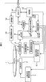
Fig. 3 is the block diagram that illustrates according to the internal configurations of the optical disc apparatus of the embodiment of the invention;
Fig. 4 illustrates the operation of carrying out when known backstage format technology is applied to multilayer disc;
Fig. 5 illustrates the operation of carrying out equally when known backstage format technology is applied to multilayer disc;
Fig. 6 illustrates the operation of carrying out when the backstage format technology of using according to the embodiment of the invention;
Fig. 7 illustrates the operation of carrying out equally when the backstage format technology of using according to the embodiment of the invention;
Fig. 8 illustrates the modification of the embodiment of the invention;
Fig. 9 illustrates user data and is recorded in state on the dish;
Figure 10 illustrates known backstage format technology;
Figure 11 illustrates the operation of carrying out when known backstage format technology is applied to multilayer disc;
Figure 12 illustrates the operation of carrying out equally when known backstage format technology is applied to multilayer disc.
Embodiment
Below, the preferred embodiments of the present invention are described.
Fig. 1 illustrates as the section structure according to the dish 1 of the optical disc recording medium of present embodiment.
For the simplification of following explanation, suppose that dish 1 is provided with two recording layers, that is, and first recording layer (layer 0) and second recording layer (layer 1).
In the present embodiment, two recording layers are formed by phase change recording film.Dish 1 has therebetween the structure with stacked two layers in less relatively interval.
As shown in Figure 1, first recording layer is set at the side near the object lens 3a of optical take-up apparatus 3 in the following disk drive device, and second recording layer is set at the opposite side away from object lens 3a.
In the recording operation of on this dual layer discs, carrying out, converge to by object lens 3a on the arbitrary layer the recording layer from optical take-up apparatus 3 emitted laser, and signal is recorded on the recording layer of convergent laser.
With reference to Fig. 2, the plot structure of dish 1 shown in the figure.
In this case, for dish 1, use backlight path system.
R1 from figure and R2 as can be seen, in this backlight path system, from the internal side diameter of first recording layer to the external diameter of first recording layer, record data successively of the internal side diameter from the outside diameter of second recording layer to second recording layer then.
In this recording processing, in first recording layer of beginning data recording, form Lead-In Area, data field and mesozone with the order from the internal side diameter to the outside diameter.In second recording layer, form mesozone, data field and leading-out zone with the order from the outside diameter to the internal side diameter.
In Lead-In Area, the record such as media type information and management information, the dish 1 on the necessary various types of information of recoding/reproduction.In the data field, user data.
On the radial distance zone far away, add the mesozone than layer to layer transition part.This mesozone is that backlight path system is necessary; this be because; reproduction pattern device reading and recording is at the pit of panel surface; therefore and in the zone that pit is not set, can not carry out servo operation reading of data stably; and it is essential for example writing down zone pseudo-data, that be used to protect.
Equally, leading-out zone also has defencive function, for example the pseudo-data of record in this district.
Fig. 3 is the block diagram that the internal configurations of disk drive device is shown, and this disk drive device is used for executive logging on dish 1 as the pen recorder according to present embodiment.
Disk drive device in the present embodiment is configured to carry out and is called the formative format processing in backstage, and this disk drive device is used as and is the pen recorder of dish 1 compatibility of DVD+RW dish.
This backstage format is a kind of like this format technology,, automatically performs the record of pseudo-data on the data field of dish 1 that is, is not carrying out any the writing or read operation to coiling 1 simultaneously in disk drive device, i.e. idle condition.This pseudo-data recording is that feasible dish 1 can be played necessary in a reproduction pattern device.
In addition, in the format of this backstage, derive (mesozone) and be added to the end in the zone of user data.Formatd fully when not being performed when its mid-game 1 even this makes, coil and also can in a reproduction pattern device, be played with a so-called endization of reproduction pattern device compatibility.
These operations above-mentioned are known, therefore ignore its explanation.
Being configured to according to the disk drive device of present embodiment can not only be on the dish 1 that is the DVD+RW dish, and can be on such as the DVD dish of other type of DVD-ROM, DVD-R, DVD+R and DVD-RW dish so-called many drive units of executive logging and/or reproduction.
Return Fig. 3, dish 1 or other DVD dish are placed on the rotating disk (not shown), and are driven by Spindle Motor 2 in the process of recoding/reproduction operation, to rotate with constant linear velocity (CLV) or constant angular velocity (CAV).The form that optical take-up apparatus 3 reads with the pit that extrudes, dyestuff variation pit or phase transformation pit is recorded in the data of coiling on 1.
Optical take-up apparatus 3 comprises laser diode, the photoelectric detector that is used for detection of reflected light that is used as lasing light emitter, object lens, optical system and two axis mechanisms that are used as laser output.Optical system by object lens with laser radiation to the recording surface of dish, and will be directed to photoelectric detector from the light of dish recording surface reflection.Diaxon mechanisms grip object lens make object lens to move along tracking direction and focus direction.
By slide drive 4, overall optical pick device 3 can move along disc radial.
Detect and be converted into the electric signal corresponding from the optical information of dish reflection by photoelectric detector with the amount that receives light.Electrical signal converted is supplied to RF amplifier 8.
In reproduction signal processor 9, the reproducing signal RF that is provided by RF amplifier 8 stands to produce, be used for the decoding processing of EFM plus signal (eight to 16 modulation signals) and the processing of correction processing such as binarization, pll clock.
Being buffered in data among the DRAM 11 is read, transmits and be output as the reproduction output of disk drive device.
Adding to separate and be in harmonious proportion in the information that the error correction operation obtains by the RF signal being carried out EFM, the information that reproduction signal processor 9 is extracted such as subcode information, atip information, LPP information, ADIP information, and with the information providing controller 12 of extraction.
In backstage format, controller 12 is configured to carry out the record of pseudo-data in the unit of booking situation piece BF, and each in these unit is as the smallest record unit.In this case, the smallest record unit that is used for pseudo-data recording can be ECC (error correction code) piece (16 sector).
According to predetermined recording order execution pseudo-data recording in this case.Especially, controller 12 is configured to meet the information that is stored among the ROM that for example wherein comprises, and the indication of this information is used to coil the record order of 1 pseudo-data, suitably implements pseudo-data recording with predetermined order thus.
Thus, the reproduction data that are stored among the DRAM 11 are output and are sent to main process equipment via host interface 13.
The read/write command, record data and other signal that send from main process equipment are buffered in the DRAM 11 or via host interface 13 and are fed into controller 12.
This from main process equipment write order and the supply of record data make the data that are recorded on the dish 1 be performed.
In data recording, the record data that 14 pairs of modulators are buffered among the DRAM 11 are carried out necessary processing.This processing comprises that error correction code is added and EFM adds modulation.
Then, the record data of modulation are supplied to Laser Modulation circuit 15.According to record data, the semiconductor laser that Laser Modulation circuit 15 drives in the optical take-up apparatus 3 is so that the output laser corresponding with record data writes data in the dish 1 thus.
In the process of recording operation, controller 12 carry out control make optical take-up apparatus 3 with the recording power level with laser radiation to the posting field of dish 1.
When dish 1 was to use the dyestuff changing film as the Write-once disc of recording layer, the irradiation of the laser on the recording power level changed dyestuff, and this causes the formation of pit.
When coiling 1 is when having the rewritable disk of phase change recording layers, and the temperature rising that is caused by laser changes the crystal structure of recording layer, thereby causes the formation of phase transformation pit.Therefore, according to the existence of pit/do not exist and the length of pit writes down various types of data.When shining again with laser when having formed pit regional, the crystal state that changes in data recording process recovers its virgin state.Therefore, pit disappearance and obliterated data thus.
Particularly, servo controller 10 produces focus drive signal and follows the tracks of drive signal according to focus error signal FE and tracking error signal TE, and the drive signal that produces is supplied with focusing/tracking driving circuit 6.Focusing/tracking driving circuit 6 drives the focusing coil and the tracking coil of two axis mechanisms in the optical take-up apparatus 3.Thus, form follow-up servo loop and focus servo loop by optical take-up apparatus 3, RF amplifier 8, servo controller 10, focusing/tracking driving circuit 6 and two axis mechanisms.
In order to connect focus servo, must at first carry out the focused search operation.Focused search operation purpose is, can obtain the position of the S shape curve of focus error signal FE when the detection focus servo is turned off when forcing mobile object lens.Scope as well known to those skilled in the art, that the linear segment representative of the S shape curve of focus error signal can enter object lens position focal position by closed focus servo loop.Therefore, by detected focus position scope when forcing mobile object lens, and, carry out the focused search operation by connecting focus servo based on the timing that detects.This focus servo operation can make laser spots keep focus state.
Under the situation of present embodiment, dish 1 can have the double-decker that is made of first recording layer (layer 0) and second recording layer (layer 1) as mentioned above.
What can be considered is that when executive logging on first recording layer/reproduction was operated, laser must focus on first recording layer.Similarly, when executive logging on second recording layer/reproduction was operated, laser must focus on second recording layer.
This focal position of carrying out between first recording layer and second recording layer by the focus jump operation is offset.
When laser is focused on the layer, by closing focus servo forcing mobile object lens, and connect focus servo by the point (promptly at the point of observing S shape curve) of the position in the focal position scope that arrives another layer at object lens, carry out the focus jump operation.
And servo controller 10 is supplied with Spindle Motor driving circuit 7 to the main shaft drives signal that produces according to spindle error signals SPE.Response main shaft drives signal, Spindle Motor driving circuit 7 is supplied with Spindle Motor 2, the rotation of drive shaft motor 2 thus to for example three-phase driving signal.Main shaft kick/brake control signal that servo controller 10 response slave controllers 12 are supplied with also produces the main shaft drives signal, makes thus that Spindle Motor driving circuit 7 is carried out beginning such as Spindle Motors 2, stopped, acceleration and deceleration operation.
And servo controller 10 produces the slippage errors signal as the low-frequency component acquisition of tracking error signal TE, and also generation slip drive signals such as control signal are carried out in the access of supplying with according to slave controller 12.Servo controller 10 is supplied with slip driving circuit 5 with the signal that produces then.Slip driving circuit 5 response slip drive slide drives 4.Slide drive 4 has by for example sled motor, transmission gear and is used for mechanism's (not shown) that the main shaft of clamping optical take-up apparatus 3 constitutes.Response slip drive signal, slip driving circuit 5 drives slide drive 4, slides to carry out the essential of optical take-up apparatus 3.
In the present embodiment, disk drive device being shown is and situation such as the irrelevant external driver device of the main process equipment (signal conditioning package) of personal computer.But disk drive device can be included in the built-in disk drive device in this signal conditioning package.
In addition, in this case, disk drive device is configured to only compatible with the DVD dish.But disk drive device also can be configured to for the optical disc recording medium work such as other type of CD (compact-disc).
Be used for the current available backstage format that the DVD+RW dish of a recording layer is only arranged, the record of pseudo-data is configured to be performed successively from internal side diameter according to the record order of user data.
Therefore, can propose, this known backstage format technology can be applied to the dish 1 of the embodiment of the invention, and this dish 1 is the DVD+RW dish with a plurality of recording layers.
Fig. 4 illustrates as the situation of known technology since the internal side diameter of first recording layer and carry out the formative situation in backstage successively on dish 1.
Similar with above-mentioned Fig. 2, by its plot structure dish 1 is shown.
Under situation shown in Figure 4, only user data piece UD 1 on the innermost zone of the data field of first recording layer then, in the idle condition that drives, carries out the backstage format on piece BF 1, BF 2 and BF 3.
Under this condition shown in Figure 4, suppose the record of another user data block of indication UD 2, so, in other words record UD2. supposes with user data block UD 2 to rewrite formative districts, the executed backstage (situation of piece BF1~BF3) in the big district of the ratio BF 1~BF3 that follows user data block UD 1 closely.
And, suppose such a case, that is, behind the record of finishing user data block UD 2, shown in Fig. 5 A, follow dish is proposed the proposition dish ejection request with the request of a reproduction pattern device compatibility.
Respond this request, shown in Fig. 5 B, on the terminal position of the user data block UD2 that the radial distance ratio writes down zone far away, add temporary mesozone.More specifically, in this case, be discontinuous on some positions in the track that is recorded in first recording layer of user data.Write down discontinuous position as the layer to layer transition position, and on the radial distance position far away, follow the mesozone closely thus, shown in Fig. 5 B than terminal position.The functional similarity of the function of the temporary mesozone of it this and known mesozone.
With this understanding, also in terminal position (that is, the terminal position of user data block UD 2) the near position of radial distance than the user data block of record, carry out the record (format) of pseudo-data on second recording layer, this is illustrated as F in Fig. 5 B new.
Thus, on second recording layer, radial distance is terminal near regional more formatted than the zone of the piece of user data in first recording layer.Even this interpolation with temporary mesozone makes that dish 1 also can be played when its mid-game 1 is not performed by complete formative so-called endization in a reproduction pattern device.
As mentioned above, for dish 1,, must on second recording layer, carry out the record (format) of pseudo-data whenever when the only a part of record stage with the user data recorded data zone requires reproduction compatibility with a plurality of recording layers.
Therefore, when by the record order according to user data known backstage format technology being applied to this multilayer disc, the format of second recording layer is configured to carry out at the end of record segment.This causes the poor efficiency in format zone, backstage to use.
In view of the foregoing, in the present embodiment, the recording layer that the backstage format is configured to preferentially to operate from the final entry that is intended for use user data begins to carry out.
Particularly, in this recording layer that is intended for use the end user data recording operation, carry out the backstage format with the order opposite with the order of carrying out the user data record.In this case, backstage format is from the piece BF of the internal side diameter of the data field that is positioned at second recording layer, and advances to outside diameter successively.
Therefore, to format with the antipodal order execution of the order of user data backstage in this case.
Fig. 6 is illustrated in the record user data block UD similar with the user data block UD 1 among Fig. 41 back and carries out situation according to the backstage format processing of present embodiment.Among Fig. 6, Fig. 7 A and Fig. 7 B each all illustrates the plot structure of dish 1.
Similar with the situation shown in Fig. 4, suppose and on three piece BF 1, BF 2 and BF 3, carry out the backstage format, then, the record user data block UD 2 similar to the user data block UD 2 shown in Fig. 5 A causes the situation shown in Fig. 7 A thus on first recording layer.
In this case, can find from Fig. 7 A that formative zone, executed backstage is not rewritten by user data, format zone, backstage advantageously is retained in the data field.
Therefore, must only carry out the format manipulation that adds together with the mesozone on the new zone of F in be shown littler than the situation shown in Fig. 5 B, add this mesozone is to observe to follow the request of reproduction compatibility and proposition dish ejection request is necessary.
Therefore, preferentially carry out the backstage format from the recording layer that is used for the end user data recording operation.This makes format zone, backstage to be used effectively, and this can shorten the format manipulation time necessary that is used to coil ejection.
In addition, shown in above example, the backstage format is performed with the order opposite with the order of user data.This reduces the possibility that format zone, backstage is rewritten by user data, guarantees to shorten the format manipulation time necessary that is used to coil ejection thus.
Handle for the format of this backstage, as mentioned above, controller 12 is configured to based on the record order information of storage wherein, and identification will be by the order of the formative BF in backstage.Therefore, the information in the controller 12 in this case of being stored in makes it possible to achieve the above-mentioned backstage format according to present embodiment with the record order of the mode indicator dog BF opposite with the information of the record order of indication user data block UD.
More than, be that the example of dual layer discs explains the situation by coiling 1.But,, also can shorten the format time that is used to coil ejection similarly by preferentially carrying out the backstage format from the recording layer that is intended for use the end user data recording operation even when dish 1 has three or more recording layers.
And, in the present embodiment,, explained with the order opposite and carried out the formative situation in backstage with the order of user data as preferentially carrying out the formative example in backstage from the recording layer that is intended for use the end user data recording operation.Therefore, carry out backstage format this example from the internal side diameter of second recording layer successively.Therefore, for the dish that uses the backlight path, when the recording layer that is intended for use the end user data recording operation is even level, carries out the backstage format from internal side diameter successively and make and shorten the format time that is used to coil ejection with the determinacy that improves.
On the other hand, when the recording layer that is intended for use end user data record is odd-level, carry out the user data record of on odd-level, carrying out with the direction identical with the user data record of on first recording layer, carrying out.Therefore, can be successively carry out the backstage format, make to guarantee to shorten the format time that is used to coil ejection from outside diameter.
Formative another example in backstage as preferentially beginning to carry out from the recording layer that is intended for use the end user data record can also use the alter mode shown in Fig. 8.
Particularly, as shown in Figure 8, in the unit of piece, carry out backstage format: the piece BF 1 of the internal side diameter of the second recording layer data field with following order; The piece BF 2 of the internal side diameter of first recording layer; The piece BF 3 of contiguous block BF 1 in second recording layer; The piece BF 4 of contiguous block BF 2 in first recording layer; The piece BF 5 of contiguous block BF 3 in second recording layer; The piece BF 6 of contiguous block BF 4 in first recording layer; Or the like.
As mentioned above, in the present example, on second recording layer and first recording layer, alternately carry out the backstage format, represent preferentially to begin to carry out the backstage format from the recording layer that is intended for use the end user data record with above-mentioned situation is similar.Therefore, this feasible and above-mentioned known backstage format is compared and can more effectively be utilized format zone, backstage.Therefore, can advantageously shorten the format time that is used to coil ejection.
In addition, when the quantity N of recording layer is two or more for a long time, in this alter mode, can carry out backstage format with each piece of the internal side diameter of each recording layer of inferior ordered pair from N recording layer to first recording layer and handle.Then, for each recording layer in each piece of formatted vicinity, can carry out the backstage format similarly successively from N recording layer to first recording layer and handle.
In the present embodiment, the situation of coiling 1 use backlight path has been described.But, use each recording layer to have under the situation of directional light path of identical recordings direction at dish 1, also can be similarly preferentially begin to carry out the backstage format, make the disk formatting time that is used to coil ejection to be shortened from the recording layer that is intended for use the end user data recording operation.
Owing to be intended for use also identical with first recording layer of user data record order of the recording layer of end user data recording operation in this case, therefore, not from internal side diameter but carry out the backstage format successively from the outside diameter of the recording layer that is intended for use the end user data recording operation.This also makes and can shorten the format time that is used to coil ejection with the determinacy that improves.
Though present embodiment has been described, can in the way you want the present invention be used for other medium, as long as their overwriting data and satisfied formative specifications in backstage that is used for thereon such as DVD-RW dish and CD-RW dish in conjunction with DVD+RW dish.
It will be appreciated by those skilled in the art that and to propose various modifications, combination, recombinant and change according to designing requirement and other factors, as long as they are in the scope of appending claims or its equivalent.
Claims (2)
1. pen recorder is used for having a plurality of recording layers and executive logging on the optical disc recording medium of overwriting data thereon, and this pen recorder comprises:
Recording-member, this recording-member are used for carrying out data recording on each recording layer of described recording medium; With
The record controls parts, these record controls parts are used to control described recording-member, make in described a plurality of recording layers, preferentially begin to carry out the record of pseudo-data from the recording layer that is intended for use the end user data recording operation,
Wherein, described record controls parts are controlled described recording-member, make preferentially to begin to the record that is intended for use to carry out pseudo-data that described zone is arranged in the recording layer that is used for the end user data recording operation in the zone of preceding recording operation from the regional order that is intended for use the end user data recording operation.
2. recording method that is used for pen recorder, described pen recorder are used for having a plurality of recording layers and executive logging on the optical disc recording medium of overwriting data thereon,
Wherein, in described a plurality of recording layers, preferentially begin to carry out the record of pseudo-data from the recording layer that is intended for use the end user data recording operation,
Wherein, preferentially begin to the record that is intended for use to carry out in the zone of preceding recording operation pseudo-data from the regional order that is intended for use the end user data recording operation, described zone is arranged in the recording layer that is used for the end user data recording operation.
Applications Claiming Priority (3)
| Application Number | Priority Date | Filing Date | Title |
|---|---|---|---|
| JP2005161429A JP4837945B2 (en) | 2005-06-01 | 2005-06-01 | Recording device |
| JP2005-161429 | 2005-06-01 | ||
| JP2005161429 | 2005-06-01 |
Publications (2)
| Publication Number | Publication Date |
|---|---|
| CN1873789A CN1873789A (en) | 2006-12-06 |
| CN100435219C true CN100435219C (en) | 2008-11-19 |
Family
ID=37484228
Family Applications (1)
| Application Number | Title | Priority Date | Filing Date |
|---|---|---|---|
| CNB2006100923144A Expired - Fee Related CN100435219C (en) | 2005-06-01 | 2006-06-01 | Recording apparatus and recording method |
Country Status (5)
| Country | Link |
|---|---|
| US (1) | US8213284B2 (en) |
| JP (1) | JP4837945B2 (en) |
| KR (1) | KR20060125585A (en) |
| CN (1) | CN100435219C (en) |
| TW (1) | TW200643935A (en) |
Families Citing this family (3)
| Publication number | Priority date | Publication date | Assignee | Title |
|---|---|---|---|---|
| MY151948A (en) * | 2005-12-06 | 2014-07-31 | Koninkl Philips Electronics Nv | De-icing of multi-layer storage media |
| JPWO2007072862A1 (en) * | 2005-12-22 | 2009-06-04 | パイオニア株式会社 | Information recording apparatus and method, and computer program |
| JP2007299447A (en) * | 2006-04-28 | 2007-11-15 | Teac Corp | Optical disk device, data recording method, and multi-layer optical disk medium |
Citations (3)
| Publication number | Priority date | Publication date | Assignee | Title |
|---|---|---|---|---|
| JP2004288362A (en) * | 2004-04-26 | 2004-10-14 | Ricoh Co Ltd | Information recording method, information recorder, information recording program, and storage medium |
| JP2004342181A (en) * | 2003-05-14 | 2004-12-02 | Ricoh Co Ltd | Information recording method, information recording device, and program for recording information, and storage medium |
| JP2005093032A (en) * | 2003-09-19 | 2005-04-07 | Ricoh Co Ltd | Information recording method, information recording device, program for recording information, and storage medium |
Family Cites Families (6)
| Publication number | Priority date | Publication date | Assignee | Title |
|---|---|---|---|---|
| JP2002117627A (en) * | 2000-10-05 | 2002-04-19 | Sony Corp | Data recorder and method for recording data ! magnetic disk unit |
| JP2005018919A (en) * | 2003-06-26 | 2005-01-20 | Sony Corp | Recording medium, recording/reproducing apparatus, and recording/reproducing method |
| JP2005025821A (en) * | 2003-06-30 | 2005-01-27 | Sony Corp | Recording medium, recording and reproducing apparatus, recording and reproducing method |
| US7164640B2 (en) * | 2005-03-01 | 2007-01-16 | Ricoh Company, Ltd. | Information storage method that assures compatibility of writable medium with read only medium |
| US8081549B2 (en) * | 2005-03-14 | 2011-12-20 | Ricoh Company, Ltd. | Information recording and reproducing apparatus and a method of controlling an information recording and reproducing apparatus |
| JP2006294101A (en) * | 2005-04-07 | 2006-10-26 | Ricoh Co Ltd | Information recording/reproducing device |
-
2005
- 2005-06-01 JP JP2005161429A patent/JP4837945B2/en not_active Expired - Fee Related
-
2006
- 2006-05-17 US US11/434,883 patent/US8213284B2/en not_active Expired - Fee Related
- 2006-05-19 TW TW095117767A patent/TW200643935A/en not_active IP Right Cessation
- 2006-06-01 KR KR1020060049383A patent/KR20060125585A/en not_active Application Discontinuation
- 2006-06-01 CN CNB2006100923144A patent/CN100435219C/en not_active Expired - Fee Related
Patent Citations (3)
| Publication number | Priority date | Publication date | Assignee | Title |
|---|---|---|---|---|
| JP2004342181A (en) * | 2003-05-14 | 2004-12-02 | Ricoh Co Ltd | Information recording method, information recording device, and program for recording information, and storage medium |
| JP2005093032A (en) * | 2003-09-19 | 2005-04-07 | Ricoh Co Ltd | Information recording method, information recording device, program for recording information, and storage medium |
| JP2004288362A (en) * | 2004-04-26 | 2004-10-14 | Ricoh Co Ltd | Information recording method, information recorder, information recording program, and storage medium |
Also Published As
| Publication number | Publication date |
|---|---|
| JP4837945B2 (en) | 2011-12-14 |
| TW200643935A (en) | 2006-12-16 |
| JP2006338770A (en) | 2006-12-14 |
| TWI371751B (en) | 2012-09-01 |
| US20060274626A1 (en) | 2006-12-07 |
| US8213284B2 (en) | 2012-07-03 |
| CN1873789A (en) | 2006-12-06 |
| KR20060125585A (en) | 2006-12-06 |
Similar Documents
| Publication | Publication Date | Title |
|---|---|---|
| US7940636B2 (en) | Recording medium, recording apparatus and recording method | |
| US7082089B2 (en) | Data recording apparatus, data recording method, and optical recording medium including pseudo-erasing features | |
| CN1327437C (en) | Storage medium, recording/reproducing apparatus, and recording/reproducing method | |
| US7227831B2 (en) | Recording medium, recording and reproduction apparatus, and recording and reproduction method | |
| JP2003030844A (en) | Optical disk information recorder and optical disk | |
| US7539114B2 (en) | Recording apparatus and recording method | |
| CN100435219C (en) | Recording apparatus and recording method | |
| KR20050003343A (en) | Information storage medium, method and apparatus for recording and/or reproducing pointing information | |
| US20070047398A1 (en) | Recording apparatus and recording method | |
| JP4488316B2 (en) | Information recording medium, information recording apparatus and method, and computer program | |
| WO2006003978A1 (en) | Information recording medium, information recording device, and computer program | |
| US7440376B2 (en) | Operation condition setting system | |
| JP4877409B2 (en) | Recording apparatus and recording method | |
| JP4345475B2 (en) | Disc playback apparatus and method | |
| JP2006338771A (en) | Recording apparatus, recording method, and optical disk recording medium | |
| JPWO2006107033A1 (en) | Information recording apparatus and method, computer program for recording control, and information recording medium | |
| JP2005322309A (en) | Recording device and method | |
| JPWO2007094452A1 (en) | Information recording medium, information recording apparatus and method, and computer program for recording control | |
| JP2005196880A (en) | Data reproducing apparatus and data reproducing method | |
| KR20090083578A (en) | Method and apparatus for recording data on disc | |
| JP2008234764A (en) | Information recording device and recording medium |
Legal Events
| Date | Code | Title | Description |
|---|---|---|---|
| C06 | Publication | ||
| PB01 | Publication | ||
| C10 | Entry into substantive examination | ||
| SE01 | Entry into force of request for substantive examination | ||
| C14 | Grant of patent or utility model | ||
| GR01 | Patent grant | ||
| C17 | Cessation of patent right | ||
| CF01 | Termination of patent right due to non-payment of annual fee |
Granted publication date: 20081119 Termination date: 20130601 |