CN100433539C - Motor control apparatus and electric appliance using the same - Google Patents
Motor control apparatus and electric appliance using the same Download PDFInfo
- Publication number
- CN100433539C CN100433539C CNB2005100650072A CN200510065007A CN100433539C CN 100433539 C CN100433539 C CN 100433539C CN B2005100650072 A CNB2005100650072 A CN B2005100650072A CN 200510065007 A CN200510065007 A CN 200510065007A CN 100433539 C CN100433539 C CN 100433539C
- Authority
- CN
- China
- Prior art keywords
- load current
- value
- motor
- sine function
- total value
- Prior art date
- Legal status (The legal status is an assumption and is not a legal conclusion. Google has not performed a legal analysis and makes no representation as to the accuracy of the status listed.)
- Expired - Fee Related
Links
Images


Classifications
-
- H—ELECTRICITY
- H02—GENERATION; CONVERSION OR DISTRIBUTION OF ELECTRIC POWER
- H02P—CONTROL OR REGULATION OF ELECTRIC MOTORS, ELECTRIC GENERATORS OR DYNAMO-ELECTRIC CONVERTERS; CONTROLLING TRANSFORMERS, REACTORS OR CHOKE COILS
- H02P1/00—Arrangements for starting electric motors or dynamo-electric converters
-
- H—ELECTRICITY
- H02—GENERATION; CONVERSION OR DISTRIBUTION OF ELECTRIC POWER
- H02P—CONTROL OR REGULATION OF ELECTRIC MOTORS, ELECTRIC GENERATORS OR DYNAMO-ELECTRIC CONVERTERS; CONTROLLING TRANSFORMERS, REACTORS OR CHOKE COILS
- H02P25/00—Arrangements or methods for the control of AC motors characterised by the kind of AC motor or by structural details
- H02P25/02—Arrangements or methods for the control of AC motors characterised by the kind of AC motor or by structural details characterised by the kind of motor
- H02P25/10—Commutator motors, e.g. repulsion motors
- H02P25/14—Universal motors
Abstract
A microprocessor of the motor control apparatus acquires a zero-cross detection signal from a zero-cross detection section and a load current from a current detection section at a prescribed sampling period. The processor obtains a load current instant value every sampling period and a corresponding sine-functional value from a sine-functional value table to calculate a compensation value for the load current instant value. The processor also calculates a load current compensation total value by adding the compensation value by the predetermined number of times of sampling and compares the load current compensation total value with a load current reference value to obtain a difference therebetween. In response to the difference, an instruction value for delay time that determines the output timing of a trigger signal to a switching element is changed so that power consumption of the motor falls within a prescribed range.
Description
Technical field
Usually the present invention relates to a kind of motor control apparatus, specifically, relate to the apparatus operating and electrical equipment of the driving motor of a kind of control AC (interchange) with this motor control apparatus.
Background technology
In the driving motor of AC, the control of its power is generally implemented based on the load current value of the motor of flowing through.Yet, because the inductive of the winding of motor may produce phase difference between voltage and current.In addition, the impedance of winding also changes in motor respectively.The load current of motor separately is identical even flow through, and still can observe because the variation of the power consumption in motor that phase difference mentioned above causes.Therefore, even the identical voltage that will stipulate is applied to the variation that still needs the governor motor power consumption on each motor.
The method of this power consumption of generally taking of adjusting is to detect electric current and voltage and based on the variation in electric current that is detected and the voltage-regulation power consumption by known method.According to this method, because the detection of electric current and voltage is inevitably, so circuit structure is complicated.
Summary of the invention
Therefore, an object of the present invention is,,, still can reduce the variation of the power consumption of motor effectively by using the motor control circuit structure of simplifying even during the impedance variation of the winding in motor.
For realizing above-mentioned purpose, provide a kind of motor control apparatus of controlling the operation of AC driving type motor to comprise:
Switch element by start trigger signal;
Be configured to detect the zero passage detection part of the zero crossing that is applied to the AC supply voltage on the motor;
Be configured to detect the current detecting part of load current of motor of flowing through; With
With zero passage detection part and the partly related control section of current detecting, it is configured to triggering signal is flowed to switch element, and this control section comprises,
By first device that divides the load current that detects to obtain the load current instantaneous value by current detecting part in predetermined sampling period sampling,
The functional value output device of the predetermined sampling period output sine function of responsive load electric current,
Total value calculation apparatus, based on obtaining the offset of load current instantaneous value from the load current instantaneous value of first device with from the sine function of functional value output device, with the number of times computational load current compensation total value by this offset sampling that adds up and
Regularly determine device, obtain a difference by load current compensation total value and load current reference value are compared, this difference is determined to the output timing of the triggering signal of switch element so that the power consumption of motor drops in the predetermined scope to respond.
Description of drawings
In conjunction with the accompanying drawings, by hereinafter knowing and these and other objects of the present invention easier to understand and advantage to the detailed description of current preferred examples embodiment of the present invention:
Accompanying drawing 2 is depicted as the view of voltage waveform, current waveform and the signal waveform of the corresponding part in accompanying drawing 1;
Accompanying drawing 3 is depicted as the view of the sine function table that uses in first embodiment;
Accompanying drawing 4 is depicted as the calcspar at the control section shown in the accompanying drawing 1;
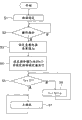
Accompanying drawing 5 is depicted as the flow chart of the main program of carrying out by the microprocessor of first embodiment;
Accompanying drawing 6 is depicted as the flow chart of the current detecting program of carrying out by the microprocessor of first embodiment;
Accompanying drawing 7 is depicted as the flow chart of the zero passage program of carrying out by the microprocessor of first embodiment;
Accompanying drawing 8 is depicted as the flow chart of the triggering signal output program of carrying out by the microprocessor of first embodiment;
Accompanying drawing 10 is depicted as the perspective view of electric vacuum cleaner according to a second embodiment of the present invention;
Accompanying drawing 12 is depicted as the view of the tables of data of using in a second embodiment;
Accompanying drawing 13 is depicted as the flow chart of the zero passage program of microprocessor in a second embodiment; With
Accompanying drawing 14 is depicted as the improved flow chart of zero passage program in a second embodiment.
Embodiment
With reference now to the present invention of accompanying drawing more detailed description.Yet identical label is applied to similar elements in the accompanying drawing, therefore, no longer repeats the detailed description to them.
(first embodiment)
1 first embodiment is described with reference to the accompanying drawings.Accompanying drawing 1 is depicted as motor control apparatus 100.Switch element 1 for example bi-directional triode thyristor (TRIAC hereinafter referred to as), current detecting part 3, electric current fuse 5 and the driving motor 7 of AC all is connected in series with commercial AC power supply 9.TRIAC 1 is with start trigger signal, and can be replaced by other the element that also drives with triggering signal.
Motor 7 is a kind of universal motors, and it comprises an armature 7a and the winding 7b with rectifier, 7c.Current detecting part 3 comprises current transformer or the shunt resistance that for example is used to detect by the load current of motor 7.The zero crossing that is applied to the AC voltage on the motor 7 detects by zero passage detection part 11.
As can be seen, control section 13 comprises microprocessor 15, memory 17 and I/O port one 9 from accompanying drawing 1.I/O port one 9 is equipped with the A/D translation function.In memory 17, the control program of operating microprocessor 15 is all stored in advance with comprising by the data of the required several constants of microprocessor 15 implementation and operations on function.Memory 17 comprises the data field and the service area that is used for microprocessor 15 of storing provisionally from the data of microprocessor 15.
Present to I/O port one 9 after carrying out full-wave rectification by the detection electric current that current detecting part 3 detects by full-wave rectifier 21.Then, collect when detecting electric current at I/O port one 9, the A/D function by I/O port one 9 will be converted to digital value from the analogue value through the detection electric current of full-wave rectification.The zero passage detection signal that detects by zero passage detection part 11 also is input to I/O port one 9.
In motor control apparatus 100, in the time will being applied to from the supply voltage with the waveform as shown in (a) of accompanying drawing 2 of commercial AC power supply 9 on the TRIAC 1 and extremely going up, be applied between the terminal of motor 7 up to the pole reversal of supply voltage and at the voltage shown in (d) of accompanying drawing 2 with triggering signal conducting TRIAC 1 with the control that the timing as shown in (c) of accompanying drawing 2 will be applied to TRIAC 1 from the triggering signal of control part 13.
At this moment, be input in the I/O port one 9 of control section 13 at the zero passage detection signal shown in (b) of accompanying drawing 2.Also pass through the load current detection waveform of full-wave rectifier 21 full-wave rectifications shown in (e) of accompanying drawing 2 by what current detecting part 3 detected.Conduction angle φ (%) calculates by following formula:
φ={(Tv/2)-t}/(Tv/2)×100 ......(1)
Wherein Tv (sec) is the cycle of supply voltage, and t (sec) is up to the time of exporting triggering signal after supply voltage reaches zero crossing.Hereinafter, time t (sec) is called time of delay.
4 every kind of function implementing by control section 13 is described with reference to the accompanying drawings.Control section 13 comprises instantaneous value collecting part 31, functional value output 33, total value calculating section 35 and the timing determining section 37 that is used for load current.Instantaneous value collecting part 31 is gathered the load current instantaneous value In that detects by current detecting part 3 in the predetermined sampling period, and this load current instantaneous value In is exported to total value calculating section 35.Functional value output 33 is gathered sine function An according to the number of times of gathering load current instantaneous value In, and this sine function An is exported to total value calculating section 35.
Total value calculating section 35 calculates the offset Jn that is used for load current instantaneous value In by load current instantaneous value In be multiply by sine function An.Total value calculating section 35 is by the offset Jn that adds up equal the to sample further computational load current compensation of the number of times total value Jsum of number of times of load current instantaneous value In, and this load current compensation total value Jsum is exported to regularly determining section 37.Regularly determining section 37 comparison load current compensation total value Jsum and predetermined load current reference value Jg are to obtain the difference between them.Regularly further calculating is used for the command value Ts of time of delay and exports triggering signal according to command value Ts determining section 37 based on this difference.
As shown in Figure 5, control section 13 is implemented main program according to the control program that is stored in advance in the memory 17.In step S1, carry out initialization procedure.In step S2, when the command signal that detects from operation part 25, employing is-path and in step S3, set load current reference value Jg.Otherwise, adopt not-path and repeating step S2.In step S4, with command value Ts value of being set at (2 * Tv/5), and the initial set value of time of delay for example is set to Tf (Ts>Tf).Therefore, the conduction angle φ of the TRIAC 1 that calculates by formula (1) is 20 (%).
In step S5, the initial set value Tf of command value Ts and time of delay compares and adopts not-path during greater than the initial set value Tf of time of delay at command value Ts.In step 6 command value Ts is deducted α, execution in step 5 then.Repeating step 5 and 6 reaches the initial set value Tf of time of delay up to command value Ts, increases the supply voltage presented to the motor 7 shown in the accompanying drawing 1 thus gradually to implement so-called soft start.When command value Ts reached the initial set value Tf of time of delay, employing was-path and carry out major cycle in step 7 in step 5.
Under the execution of major cycle, instantaneous value collecting part 31 is implemented in the current detecting program shown in the accompanying drawing 6 termly with the timer (not shown).
The current detecting program of carrying out by instantaneous value collecting part 31 is hereinafter described.
In step S11, the number of times of implementing the current detecting program is counted.The current detecting program implementation is identical with the execution of current sample, and therefore, timer has been set the current sample cycle.For example, be set at 0.2msec, implement current sample 100 times down at the one-period (20msec) of AC power in the AC power down-sampling cycle of 50Hz.Therefore, be understandable that, when the number of times of carrying out the current detecting program count down to 100 times, finished the one-period of AC supply voltage.
Further in step S12, instantaneous value collecting part 31 receives load current instantaneous value In from I/O port one 9, and in step S13, functional value output 33 obtains corresponding sine function An based on count value (carrying out the number of times of current detecting program) from the sine function table 27 of storage the memory shown in the accompanying drawing 3 17.
As shown in Figure 3, going up sine function at each differential seat angle { θ (n)-θ (n-1) } is set in respectively in the sine function table 27.Differential seat angle { θ (n)-θ (n-1) } is by expression formula (360 °/(Tv/Ti)) expression, and wherein Ti is the current sample cycle.For example, be 50Hz and Ti when being 0.2 (msec) in AC power, the sine values of per 3.6 degree are set in the table 27 as sine function An.
Sine function An in the one-period of supply voltage can be set in the table 27.Yet, because the absolute value of the sine function An in the supply voltage of first half period is identical with the absolute value in the follow-up half period, thereby the sine function in first half period can be set in the sine function table 27, and the sine function in the follow-up half period can obtain from the sine function table 27 then.Repeat this operation to obtain sine function.
For example, if sampling period Ti is 0.2 (msec), then sine function A1-A50 is set in respectively in the sine function table 27.If carrying out the count value of the number of times of current detecting program (current sample cycle) is 1, then when sine function A1 obtains,, then from table 27, obtain identical sine function A1 from table 27 if count value is 51.
As can be seen, in step S14, total value calculating section 35 calculates the offset Jn that is used for load current instantaneous value In by load current instantaneous value In and sine function An are taken advantage of together from accompanying drawing 6.Repeat this calculating operation as indicated abovely.In step S15, will be obtained load current compensation total value Jsum mutually by the offset Jn that calculating operation calculates respectively.For example, if computing cycle is that a half period and the sampling period Ti of supply voltage (50Hz) is 0.2 (msec), i.e. 20 (msec)/2/0.2 (msec)=50, offset Jn addition that then will be from a zero crossing of supply voltage to 50 times calculating of next zero crossing.In addition, for example, if computing cycle is the one-period of supply voltage (50Hz), then with the offset Jn addition from for 100 times of first zero crossing to the, three zero crossings (one-period) calculating of supply voltage.After this, this operation is turned back at the step S7 (major cycle) shown in the accompanying drawing 5.
Under the execution of the processing of the major cycle in step S7, when arriving zero crossing based on zero passage detection input from zero passage detection part 11, the zero passage program that control section 13 is implemented as shown in accompanying drawing 7.In the zero passage program, the command value Ts of the time of delay of the output timing of timing determining section 37 definite instruction triggers signals.
7 instantiations of describing definite process of command value Ts with reference to the accompanying drawings.In step S21, regularly determining section 37 compares load current reference value Jg and load current compensation total value Jsum.When the difference between load current reference value Jg and the load current compensation total value Jsum is in Δ J1, employing is-path and keep current instruction value Ts.Otherwise, adopt not-path.In the time of in step S24 and S25, to the counter O reset of the counting of the execution number of times that detects electric current and also to load current compensation total value Jsum zero clearing.Then, zero clearing delay timer and restarting in step S26, and this operation turned back among the step S7 that carries out major cycle.In this case, operate in predefined power consumption range by motor control apparatus 100 definite motors 7.
In step S22, when deducting value that load current compensation total value Jsum obtains greater than Δ J1 from load current reference value Jg, employing is-path.Command value Ts reduces γ in step S27, carry out above-mentioned step S24, S25 and S26 then.In this case, determine that by motor control apparatus 100 power consumption of motor 7 is under default scope.Therefore, the conduction angle φ of TRIAC 1 increases so that the electrical power that is applied on the motor 7 can increase.
In step S22, adopt not-during the path, in step S23, make command value Ts increase β.After this, carry out above-mentioned step S24, S25 and S26.In this case, determine that by motor control apparatus 100 power consumption of motor 7 is on predefined scope.Therefore, the conduction angle φ of TRIAC1 reduces so that the electrical power that is applied on the motor 7 can reduce.
At last, regularly the delay timer (not shown) of determining section 54 by zero clearing in step S26 from zero crossing to counting time of delay, and regular as shown in Figure 8 execution triggering signal output program.In step S31, when the count value of delay timer does not reach command value Ts, adopt not-path and operation turned back to step S7.Otherwise employing is-path and in step S32, triggering signal exported to TRIAC 1, and this operation is turned back to step S7.
In the above-described embodiment, motor control apparatus 100 is based on load current instantaneous value In and the sine function An computational load current compensation total value Jsum that sets based on the zero crossing of AC supply voltage.Therefore, load current compensation total value Jsum is load current data of having considered the phase difference calculating between mains voltage waveform and load current waveform.
In addition, the power consumption of motor 7 is identified for the command value Ts control of the time of delay of triggering signal by the difference of basis between load current compensation total value Jsum and predetermined load current reference value Jg.In prior art, because the difference of the winding of each motor, the therefore difference of phase difference between mains voltage waveform and load current waveform, result, the power consumption difference in the motor.In this case, the motor control apparatus 100 of present embodiment can be reduced in the variation of the power consumption in the motor.
Usually, and compare in the computational process of microprocessor 15, the A/D conversion process needs the time.Yet motor control apparatus 100 can be implemented the control of power consumption, and this can be reflected in the phase difference between an inherent power supply wave shape of relatively short time and the load current waveform.This is because the motor control apparatus 100 of present embodiment is only carried out the A/D conversion process of current value.
In addition, in the above-described embodiment, by the load current compensation total value Jsum that will obtain in the offset Jn addition of the corresponding load current instantaneous value In in the predetermined sampling period (a for example half period of supply voltage).Therefore, even load current instantaneous value In is subjected to the adverse effect of the electrical noise in the sampling period, the load calculated current compensation total value Jsum of institute still can not be subjected to bigger influence.
In addition, can simplify the structure of the motor control apparatus 100 of this embodiment.This is because do not need to utilize the specific device of the physical quantity that detects motor except zero passage detection part 11 and current detecting part 3.
In above-mentioned functional value output 33, from sine function table 27, obtain sine function An.Yet, be not limited to this method, therefore, special-purpose sine function calculator is provided can for microprocessor 15.Also can in each sampling period, calculate sine function An continuously by the sine function calculator of special use.
In above-mentioned control section 13, by in the detection of the zero crossing of supply voltage with give in cycle (non-conductive cycle) between the output of triggering signal of TRIAC 1 and also can obtain load current instantaneous value In by regular execution current detecting program.Yet, in this cycle (non-conductive cycle), may stop the current detecting program implementation.Because stop the conveying to the supply voltage of motor in this cycle, therefore load current is zero in theory.Opposite with this theoretical value, because the cause of electrical noise, load current instantaneous value In in practice may not vanishing.Therefore, the situation that may exist is that the load current compensation total value Jsum in this cycle is also non-vanishing.Yet, as described above, if stop the current detecting program implementation in the process in this cycle (non-conductive cycle), the then error vanishing for certain in load current compensation total value Jsum that is caused by electrical noise is not because produce load current instantaneous value In in this cycle.
Accompanying drawing 9 shows above-mentioned control.Accompanying drawing 9 is depicted as the flow chart based on the current detecting program of foregoing description.In step S41, the number of times of carrying out the current detecting program is counted.In step S42, elapsed time that will obtain by multiplying each other and be used for the command value of time of delay and compare in the sense cycle (sampling period) of count value among the step S41 and load current instantaneous value In.Adopt during at elapsed time and to be-path less than command value Ts.This operation turns back to step S7.Otherwise, adopt not-path.Load current instantaneous value collecting part 31 receives load current instantaneous value In by I/O port one 9 in step S43, and load current instantaneous value In is exported to total value calculating section 35.Functional value output 33 count value based on current detecting program implementation number of times in step S44 obtains sine function An from sine function table 27, and this sine function An is exported to total value calculating section 35.Then, in step S45 total value calculating section 35 by load current instantaneous value In being multiply by sine function An offset value calculation Jn.In step S46, obtain load current compensation total value Jsum by the offset Jn addition that will thitherto obtain, and operation is turned back to step S7.
As indicated above, by above-mentioned current detecting program implementation, based at the load current instantaneous value In and the sine function An offset value calculation Jn that from the cycle (conducting period of TRIAC) of the detection of next zero crossing that outputs to supply voltage of triggering signal, obtain, and finally obtain load current compensation total value Jsum by the offset Jn addition that will thitherto obtain.
It is the precision of unit load calculated current compensation total value Jsum that this operation can improve with the half period between the continuous zero crossing of supply voltage.As a result, also can improve the variation of the power consumption of motor 7.In addition, the operating load of microprocessor 15 reduces, and therefore microprocessor 15 also can be implemented other operation.
Should be noted that and in the timing shown in the accompanying drawing 9, do not need execution in step S42.Can execution in step S42 in any timing before the execution of step S46 (calculating of load current compensation total value Jsum).Particularly, compare with the arithmetical operation in microprocessor 15, owing to need the time to implement the A/D conversion process, therefore preferred execution in step S42 before execution in step S43.
In the above-described embodiment, provide 21 pairs of waveforms that detect by current detecting part 3 of full-wave rectifier to carry out the load current detection waveform of full-wave rectification, and on every half period of supply voltage, pass through load current detection waveform computational load current compensation total value Jsum in the sampling period up-sampling rectification of regulation with the rectification of generation shown in (e) of accompanying drawing 2.Yet, be not limited to above-mentioned operation.Can implement following processing, promptly replace full-wave rectifier 21 but carry out the load current detection waveform of halfwave rectifier with the dotted line indication that produces (e) by accompanying drawing 2 with the waveform that diode pair detects by current detecting part 3, and use this load current detection waveform on every half period of supply voltage by sampling period sampling computational load current compensation total value Jsum with regulation.The inventor is verified, even based on the load current detection waveform computational load current compensation total value Jsum of halfwave rectifier mentioned above, still can obtain the effect of this embodiment without any obstacle ground.
In addition, under the situation of not using circuit element such as diode, can be under the condition of using full-wave rectifier by software processes (program) every half period computational load current compensation total value Jsum.For in the current detecting program, realizing this processing, at first calculate the load current compensation total value Jsum in first half period.In second half period of after this period 1, following, do not calculate load current compensation total value Jsum, so this operation turns back to main program.
As indicated above, because every half period computational load current compensation total value Jsum, so the reduction of the operating load of microprocessor 15, so microprocessor 15 can be implemented other operation.
In the first above-mentioned embodiment, be set in the sine function table 27 corresponding to the sine function A1-An of the number of times of in the half period of supply voltage, sampling.Yet, in the present embodiment, be not limited to table 27, therefore the sine function A1-An corresponding to the number of times of sampling at least 1/4 cycle can be set in the sine function table 27.Owing to determine sine function A1-An based on sine wave, if therefore the sinusoidal wave number A1-An in 1/4 cycle is set in the sine function table 27, can in one-period, export sine function A1-An by the processing functional value output 33 of back.Functional value output 33 is at first sequentially exported sine function A1-An in the one 1/4 cycle, sequentially export sine function An-A1 then in the 2 1/4 cycle.Functional value output 33 is further sequentially exported sine function A1-An in the 3 1/4 cycle, finally sequentially export sine function An-A1 then in the 1/4 remaining cycle.By above-mentioned method, the data volume of setting in sine function table 27 reduces and can save thus the memory block of memory 17.
In the above-described embodiment, the processing of implementing by instantaneous value collecting part 31, functional value output 33, total value calculating section 35 and the timing determining section 37 of control section 13 can be carried out by saved software (program) in memory 17.Also can implement it by circuit structure rather than software (but it has the function of carrying out by software).
(second embodiment)
In this embodiment, describe above-mentioned first embodiment (motor control apparatus) and be applied to wherein electrical equipment, for example vacuum cleaner.
As shown in Figure 10, vacuum cleaner 51 comprises lower house 53, upper shell 55, buffer 57 and the lid 59 that its upper surface is opened.The rear section of lower house 53 is closed by upper shell 55.Buffer 57 is clipped between the periphery edge of lower house 53 and the upper shell 55 and with it and is connected.Lid 59 can be rotatably set in the front member of lower house 53 to open and close front member.
Pocket filter 61 (filter hereinafter referred to as) and electric air blast 63 in series are positioned at the inside of vacuum cleaner 51.The air communication that produces by air blast 63 is crossed filter 61 and is carried with dust and flow separation.
The Caster (not shown) is on the rear surface of the front member that forwards upwards is provided at vacuum cleaner 51, and pair of driven 65 is provided at respectively on the opposite side of back component of vacuum cleaner 51.
In the inside of vacuum cleaner 51, the circuit board of realizing the control appliance of electric air blast thereon on function has been installed.The structure of electricity air blast control appliance is basic identical with the motor control apparatus 100 in accompanying drawing 1 in one embodiment.Yet, in the present embodiment, use to comprise the electric air blast 63 of motor 7 (and being not only to have only motor 7), and also use grip 71, and do not use operation part 25 with fan (not shown).
In the electric air blast control appliance in the present embodiment, be stored in the memory 17 of accompanying drawing 1 in the tables of data shown in the accompanying drawing 12 81.In tables of data 81, n+1, U0, U1, U2, ..., Un (Un<... set point time of delay of<U2<U1<U0) is set in first row command value Ts (output of triggering signal is regularly) as time of delay, n, X1, X2, X3, ..., Xn (Xn>..., the load current reference value of>X3>X2>X1) be set in the secondary series as corresponding to command value Ts time of delay set point the first load current reference value Jg1, and n, Y1, Y2, Y3, ..., Yn (Yn>..., the load current reference value of>Y3>Y2>Y1) also is set in the 3rd row as the second load current reference value Jg2.As shown in Figure 11, the relation of the relative value size between the first load current reference value Jg1 and the second load current reference value Jg2 is as follows:
X1<X2<Y1<X3<Y2<X4<Y3<X5<,...,Xn<Yn-1<Yn
The operation of vacuum cleaner 51 is hereinafter described.
In electric air blast control appliance, control section 13 output triggering signals give TRIAC 1 with blower 63.When filter 61 is not collected dust, control section 13 from tables of data 81 selective value U0 and set point U0 as command value Ts.At this moment, for example, the operating point of electric air blast 63 is indicated with character A as shown in Figure 11.
In this state, electric air blast 63 is driven, and therefore clean operation begins to collect dust by filter 61.When clean operation carried out, the dust of collecting in filter 61 increased, so the gas-flow resistance of filter 61 increase, caused the air inflow of electric air blast 63 to reduce.Respond the reduction of this throughput, load current compensation total value Jsum reduces towards load current reference value X1 gradually from operating point A.
When load current compensation total value Jsum was lower than load current reference value X1, the command value Ts of the time of delay output of the triggering signal (regularly) was from the value U0 value of changing to U1 (U0>U1).By this operation, the conduction angle of TRIAC 1 increases, and therefore the air inflow of electric air blast 63 increases.At this moment, the load current compensation total value Jsum power consumption that becomes value Y1 and electric air blast 63 also increases.
After this, along with proceeding of clean operation, the gas-flow resistance of filter 61 also further increases, and therefore the air inflow of electric air blast 63 further reduces.At this moment, load current compensation total value Jsum reduces towards load current reference value X2.
In the time of under load current compensation total value Jsum is reduced to load current reference value X2, the command value Ts of time of delay is from the value U1 value of changing to U2 (U1>U2).By this operation, the conduction angle of TRIAC 1 further increases, and the air inflow of electric air blast 63 further increases.At this moment, load current compensation total value Jsum becomes value Y2, and the power consumption of electric air blast 63 further increases.
From description above, be appreciated that along with the proceeding of clean operation, when load current compensation total value Jsum is lower than load current reference value X1, X2, X3, X4... respectively, command value Ts change to corresponding value U0, U1, U2, U3 ....Finally become at load current compensation total value Jsum and to be lower than under the load current reference value Xn and when therefore command value Ts becomes value Un, even after this load current compensation total value Jsum further reduces, command value Ts does not still change, and determines to have collected in filter 61 enough dusts.In this case, when load current compensation total value Jsum further is reduced under the reference value of regulation, for example determine that by the indication of LED (light emitting diode) filter 61 is that full urgency operator changes filter 61.
Also be in the second above-mentioned embodiment, load calculated current compensation total value Jsum and predetermined load current reference value Jg1 are compared obtaining difference betwixt and to change command value Ts based on this difference, and therefore the power consumption of electric air blast 63 drops in the scope of regulation.In this case, respond the charge air flow amount of electric air blast 63, change the prescribed limit that load current reference value Jg1 also also so also changes power consumption.
With reference to the accompanying drawings 13, the zero passage operation sequence by the control of control section 13 indication air blasts 63 is hereinafter described.
Regularly determining section 37 in step S51, confirms current command value Ts and in step S52 acquisition corresponding to the load current reference value Jg1 of current command value Ts.In step S53, load current reference value Jg1 that will obtain in step S52 and load current compensation total value Jsum compare, and adopt during greater than load current reference value Jg1 at load current compensation total value Jsum to be-path.Otherwise, adopt not-path.In step S54 and S55, the counter that the execution number of times of current detecting is counted is cleared and also to load current compensation total value Jsum zero clearing.Then, make the delay timer zero clearing and restart in step S56, operation turns back to step S7, carries out major cycle in step S7.In step S53, adopt not-during the path, command value Ts reduces a stride in tables of data 81.For example, if command value Ts is value U0, then be worth the U0 value of changing to U1.After this, step S54, S55, S56 that inferior continuous execution is above-mentioned, and operation turns back to step S7.
As describe, also be in a second embodiment, but the power consumption Be Controlled of electric air blast 63 is considered the phase difference between power source voltage waveform and load current waveform, therefore second embodiment has realized and the first embodiment similar effects.
In addition, in a second embodiment, based on the amount of dust in filter 61, computational load current compensation total value Jsum, and change command value Ts and the load current reference value Jg1 of time of delay, thus with the power consumption control of electric air blast 63 in predetermined proper range.Therefore, the gettering ability of vacuum cleaner 51 can maintain on the proper level.In addition, even variation has taken place in the impedance of the winding in electric air blast, still can make the variation minimum of the gettering ability of vacuum cleaner.
Further, in a second embodiment, regularly the command value Ts of 37 response times of determining section from have n load current reference value X1, X2, X3 ..., acquisition load current value Jg1 in the tables of data 81 of Xn.Yet, can take regularly the method for determining section 37 by following formula output triggering signal:
Xn=X1+K*(n-1)*Ts
Wherein Xn is a n load current reference value, and X1 is the first load current reference value, and K is the constant that obtains from experimental result.
In the second above-mentioned embodiment, the gas-flow resistance along with increase of the amount of dust in filter 61 and filter 61 also increases under the prerequisite of time institute's load calculated current compensation total value Jsum reduction based on hypothesis, carries out control.Yet, also can consider since in the clean operation process cause of the flexibility of the contact relation between floor cleaner brush 89 and floor and flexible pipe 69, gas-flow resistance reduces, the charge air flow amount sharply increases.Consider this operating condition, require to use the second load current reference value Jg2 (Yn) that is different from the first load current reference value Jg1 (Xn) shown in accompanying drawing 11 and 12.
For example, if load current compensation total value Jsum becomes and is higher than load current reference value Y3 when the operating point of electric air blast 63 is in operating point B shown in the accompanying drawing 11, then from U3 to U2, change the command value Ts of the timing of determining the output triggering signal, therefore the conduction angle of TRIAC 1 reduces, and causes the charge air flow amount of electric air blast 63 to reduce.At this constantly, load current compensation total value Jsum becomes X3, and the power consumption of electric air blast 63 reduces.
14 above-mentioned operation is described in more detail with reference to the accompanying drawings.
In the program shown in the accompanying drawing 14 is that wherein step S68 and S69 are increased to the zero passage program of the program as shown in accompanying drawing 13.In this program, the step S61 in accompanying drawing 14, S63-S67 are identical with step S51, S53-S57 in accompanying drawing 13.In step S62, obtain first and second load current reference value Jg1 and the Jg2, and in step S52, only obtain the first load current reference value Jg1.
Among the step S68 in accompanying drawing 14, at load current compensation total value Jsum during more than or equal to load current reference value Jg2, employing is-path, and if command value Ts be U3 for example in step S69, command value Ts is increased a stride from U3 to U2.Become longer the time of delay of output triggering signal from timing determining section 37.In step S68, adopt not-during the path, execution in step S64.Describe the operation in step S64, S65 and S66, therefore do not repeated these operations.As indicated above, in this program, computational load current compensation total value Jsum, and the amount of dust of response in filter 61 change command value Ts, first and second load current reference value Jg1 and the Jg2.Therefore the power consumption of electricity air blast 63 is controlled in the proper range of regulation.
In the above-described embodiment, do not need to be set at the interval delta Un (Un-Un-1) of command value Ts constant.The interval delta Xn (Xn-Xn-1) of the first and second load current reference value Jg1 and Jg2 and interval delta Yn (Yn-Yn-1) are too.Difference use based on the motor that will control can be set it.
In addition, in the second above-mentioned embodiment, the present invention is applied to vacuum cleaner.Yet the present invention also can be applied to the electrical equipment that uses motor control, for example electric cooking device, motor instrument etc.
With reference to certain embodiments the present invention has been described.Yet, be obvious for those of ordinary skill in the art based on other embodiment of principle of the present invention.Therefore wish that claim contains these embodiment.
Claims (8)
1. motor control apparatus of controlling the operation of AC driving type motor comprises:
Switch element by start trigger signal;
Be configured to detect the zero passage detection part of the zero crossing that is applied to the AC supply voltage on the motor;
Be configured to detect the current detecting part of load current of motor of flowing through; With
With zero passage detection part and the partly related control section of current detecting, it is configured to triggering signal is flowed to switch element, and this control section comprises,
By first device that divides the load current that detects to obtain the load current instantaneous value by current detecting part in predetermined sampling period sampling,
The functional value output device of the predetermined sampling period output sine function of responsive load electric current,
Total value calculation apparatus, based on obtaining the offset of load current instantaneous value from the load current instantaneous value of first device with from the sine function of functional value output device, with the number of times computational load current compensation total value by this offset sampling that adds up and
Regularly determine device, be used for obtaining a difference that this difference is determined to the output timing of the triggering signal of switch element so that the power consumption of motor drops in the predetermined scope to respond by load current compensation total value and load current reference value are compared.
2. equipment according to claim 1, wherein this total value calculation apparatus calculates from the offset to the load current instantaneous value of switch element output triggering signal to the cycle of the detection of next zero crossing of supply voltage.
3. equipment according to claim 1, wherein this total value calculation apparatus computational load current compensation total value on the every at least half period that is applied to the AC supply voltage on the motor.
4. equipment according to claim 1, wherein control section comprises the sine function table with sine function, the quantity of this sine function equal the cycle shorter than the cycle of the AC supply voltage of giving motor and than 1/4 cycle of AC supply voltage the sampling number of the load current between longer cycle, and the sampling period of functional value output device responsive load electric current from the sine function table, read corresponding sine function with the corresponding sine function of output repeatedly in the cycle of AC supply voltage.
5. equipment according to claim 1 wherein in the load current compensation total value during less than the load current reference value, determines that regularly device regularly submits to switch element with the output of triggering signal.
6. equipment according to claim 1, wherein control section comprises a plurality of load current reference values, regularly preestablishes each load current reference value by control section corresponding to each output of triggering signal.
7. equipment according to claim 1, wherein control section comprises a plurality of load current reference values, and determines that regularly the output change regularly of device response triggering signal changes the load current reference value from one to another ground.
8. electrical equipment comprises:
The AC driving type motor;
Operation part by motor driven; With
Motor control apparatus comprises,
Switch element by start trigger signal;
Be configured to detect the zero passage detection part of the zero crossing that is applied to the AC supply voltage on the motor;
Be configured to detect the current detecting part of load current of motor of flowing through; With
With zero passage detection part and the related control section of current detecting part, it is configured to triggering signal is flowed to switch element,
Wherein this control section comprises:
By first device that divides the load current that detects to obtain the load current instantaneous value by current detecting part in predetermined sampling period sampling,
The functional value output device of the predetermined sampling period output sine function of responsive load electric current,
Total value calculation apparatus, based on obtaining the offset of load current instantaneous value from the load current instantaneous value of first device with from the sine function of functional value output device, with the number of times computational load current compensation total value by this offset sampling that adds up and
Regularly determine device, be used for obtaining a difference that this difference is determined to the output timing of the triggering signal of switch element so that the power consumption of motor drops in the predetermined scope to respond by load current compensation total value and load current reference value are compared.
Applications Claiming Priority (3)
| Application Number | Priority Date | Filing Date | Title |
|---|---|---|---|
| JP2004146654 | 2004-05-17 | ||
| JP2004-146654 | 2004-05-17 | ||
| JP2004146654A JP3942605B2 (en) | 2004-05-17 | 2004-05-17 | Motor control device and electrical equipment |
Publications (2)
| Publication Number | Publication Date |
|---|---|
| CN1702953A CN1702953A (en) | 2005-11-30 |
| CN100433539C true CN100433539C (en) | 2008-11-12 |
Family
ID=34934129
Family Applications (1)
| Application Number | Title | Priority Date | Filing Date |
|---|---|---|---|
| CNB2005100650072A Expired - Fee Related CN100433539C (en) | 2004-05-17 | 2005-04-12 | Motor control apparatus and electric appliance using the same |
Country Status (5)
| Country | Link |
|---|---|
| US (1) | US7026771B2 (en) |
| EP (1) | EP1597995A3 (en) |
| JP (1) | JP3942605B2 (en) |
| KR (1) | KR101108322B1 (en) |
| CN (1) | CN100433539C (en) |
Families Citing this family (19)
| Publication number | Priority date | Publication date | Assignee | Title |
|---|---|---|---|---|
| US20060204383A1 (en) * | 2005-03-08 | 2006-09-14 | Hiroyuki Kushida | Electric vacuum cleaner |
| JP4079962B2 (en) * | 2005-08-30 | 2008-04-23 | 株式会社東芝 | Electric vacuum cleaner |
| JP4621580B2 (en) * | 2005-11-09 | 2011-01-26 | 株式会社東芝 | Electric vacuum cleaner |
| DE102007060242A1 (en) * | 2007-12-14 | 2009-06-18 | Robert Bosch Gmbh | Method and device for operating an electric drive by means of a phase control |
| PL2088438T3 (en) * | 2008-02-06 | 2011-11-30 | Electrolux Home Products Corp Nv | Method and device for measuring the electric power of a universal electric motor powered by sinusoidal alternating voltage |
| EP2579050B1 (en) | 2008-07-17 | 2014-06-04 | Isis Innovation Limited | Utility metering |
| CN101841287B (en) * | 2009-03-16 | 2013-04-24 | 建准电机工业股份有限公司 | Modulated delay time control system for motor |
| EP2424419B1 (en) * | 2009-04-30 | 2022-06-08 | Aktiebolaget Electrolux | Vacuum cleaner and method for controlling an electric motor |
| CN103296962B (en) * | 2012-02-29 | 2017-08-15 | 艾默生电气公司 | The speed control of speed change multi-phase motor |
| WO2014000794A1 (en) * | 2012-06-27 | 2014-01-03 | Aktiebolaget Electrolux | Vacuum cleaners and methods of controlling a motor driven by a battery source in a vacuum cleaner |
| CN103584795A (en) * | 2012-08-17 | 2014-02-19 | 乐金电子(天津)电器有限公司 | Robot vacuum cleaner and self-diagnosing method thereof |
| GB2513193B (en) * | 2013-04-19 | 2015-06-03 | Dyson Technology Ltd | Air moving appliance with on-board diagnostics |
| US9559628B2 (en) | 2013-10-25 | 2017-01-31 | Black & Decker Inc. | Handheld power tool with compact AC switch |
| CN103546085A (en) * | 2013-11-13 | 2014-01-29 | 苏州工业园区艾思科技有限公司 | Constant-power dust collector and control method thereof |
| WO2015115137A1 (en) * | 2014-01-29 | 2015-08-06 | 日本電気株式会社 | Monitoring device, monitoring system, monitoring method, correction information creation device, correction information creation method, and program |
| CN107465368B (en) * | 2016-05-30 | 2023-09-26 | 德昌电机(深圳)有限公司 | Motor and driving circuit and driving method thereof |
| JP2018046628A (en) * | 2016-09-13 | 2018-03-22 | 株式会社東芝 | Brushless DC motor control device and brushless DC motor device |
| CN109672391A (en) * | 2019-01-14 | 2019-04-23 | 深圳博英特科技有限公司 | A kind of series excited machine control system and method |
| CN114055321B (en) * | 2021-11-06 | 2024-04-19 | 深圳华数机器人有限公司 | Grinding and polishing pressure real-time compensation method based on numerical control system |
Citations (3)
| Publication number | Priority date | Publication date | Assignee | Title |
|---|---|---|---|---|
| CN1133510A (en) * | 1994-08-25 | 1996-10-16 | 松下电器产业株式会社 | Controller for transducer |
| JP2001087189A (en) * | 1999-09-20 | 2001-04-03 | Mitsubishi Electric Corp | Input controller for vacuum cleaner |
| US6388416B1 (en) * | 1999-08-05 | 2002-05-14 | Sharp Kabushiki Kaisha | Motor control device and motor control method |
Family Cites Families (24)
| Publication number | Priority date | Publication date | Assignee | Title |
|---|---|---|---|---|
| JPS5911271B2 (en) * | 1977-12-23 | 1984-03-14 | 株式会社東芝 | Control method of induction motor |
| US4357729A (en) * | 1981-01-26 | 1982-11-09 | Whirlpool Corporation | Vacuum cleaner control |
| US4578632A (en) * | 1984-05-07 | 1986-03-25 | General Electric Company | Intergratable load voltage sampling circuit for R.M.S. load average voltage control apparatus |
| US4935678A (en) * | 1989-11-09 | 1990-06-19 | Whirlpool Corporation | Universal motor speed control circuit for hand mixer |
| US5670858A (en) * | 1991-06-03 | 1997-09-23 | Condyne Technology, Inc. | Single-phase induction motor safety controller |
| JPH05227795A (en) * | 1992-02-10 | 1993-09-03 | Alex Denshi Kogyo Kk | Controller and control method for induction motor |
| US5412303A (en) * | 1993-02-17 | 1995-05-02 | Wernicki; Paul F. | Method and apparatus providing minimal power consumption, indication of savings and fault detection |
| US5495161A (en) * | 1994-01-05 | 1996-02-27 | Sencorp | Speed control for a universal AC/DC motor |
| JPH09122052A (en) | 1995-10-31 | 1997-05-13 | Hitachi Ltd | Electric vacuum cleaner |
| KR19980023018U (en) * | 1996-10-30 | 1998-07-25 | 배순훈 | Voltage fluctuation compensation circuit of air conditioner |
| US5850132A (en) * | 1997-07-02 | 1998-12-15 | Allin-Bradley Company, Llc | Apparatus used with AC motors for compensating for turn on delay errors |
| JP2000166833A (en) | 1998-12-07 | 2000-06-20 | Sharp Corp | Vacuum cleaner |
| US6400107B1 (en) * | 1999-08-04 | 2002-06-04 | Sharp Kabushiki Kaisha | Motor control device capable of driving a synchronous motor with high efficiency and high reliability |
| GB0011030D0 (en) * | 2000-05-09 | 2000-06-28 | Savawatt Uk Ltd | Motor energisation control circuit |
| KR100446962B1 (en) * | 2000-08-25 | 2004-09-01 | 엘지산전 주식회사 | Current control apparatus for three phase alternating-current motor |
| JP3656901B2 (en) * | 2000-08-29 | 2005-06-08 | 東芝テック株式会社 | Drive control circuit using inverter control circuit of electric blower for vacuum cleaner and electric vacuum cleaner using this drive control circuit |
| JP2002345288A (en) * | 2001-05-15 | 2002-11-29 | Toshiba Tec Corp | Method of starting three-phase brushless motor, drive control circuit therefor, motor-driven blower, and vacuum cleaner |
| TW579289B (en) * | 2001-05-23 | 2004-03-11 | Toshiba Tec Kk | Vacuum cleaner |
| WO2003096523A1 (en) * | 2002-04-23 | 2003-11-20 | Risso Andrew F | Reduced energy multiple-function digital controller for motors and appliances |
| US6828753B2 (en) * | 2002-08-26 | 2004-12-07 | International Rectifier Corporation | Input filter for A.C. motor phase current sensing |
| JP2004135835A (en) | 2002-10-17 | 2004-05-13 | Toshiba Tec Corp | Vacuum cleaner |
| JP3955287B2 (en) * | 2003-04-03 | 2007-08-08 | 松下電器産業株式会社 | Inverter control device for motor drive and air conditioner |
| CN100545462C (en) | 2003-05-20 | 2009-09-30 | 东芝泰格有限公司 | Electric blowing machine and electrical equipment with this electric blowing machine |
| GB2467334A (en) * | 2009-01-30 | 2010-08-04 | Mechadyne Plc | Assembled camshaft for i.c. engines |
-
2004
- 2004-05-17 JP JP2004146654A patent/JP3942605B2/en active Active
-
2005
- 2005-03-08 EP EP05005052A patent/EP1597995A3/en not_active Withdrawn
- 2005-04-12 CN CNB2005100650072A patent/CN100433539C/en not_active Expired - Fee Related
- 2005-05-09 US US11/124,139 patent/US7026771B2/en not_active Expired - Fee Related
- 2005-05-17 KR KR1020050041220A patent/KR101108322B1/en not_active IP Right Cessation
Patent Citations (3)
| Publication number | Priority date | Publication date | Assignee | Title |
|---|---|---|---|---|
| CN1133510A (en) * | 1994-08-25 | 1996-10-16 | 松下电器产业株式会社 | Controller for transducer |
| US6388416B1 (en) * | 1999-08-05 | 2002-05-14 | Sharp Kabushiki Kaisha | Motor control device and motor control method |
| JP2001087189A (en) * | 1999-09-20 | 2001-04-03 | Mitsubishi Electric Corp | Input controller for vacuum cleaner |
Also Published As
| Publication number | Publication date |
|---|---|
| CN1702953A (en) | 2005-11-30 |
| KR101108322B1 (en) | 2012-01-25 |
| US20050253539A1 (en) | 2005-11-17 |
| JP2005328683A (en) | 2005-11-24 |
| EP1597995A2 (en) | 2005-11-23 |
| EP1597995A3 (en) | 2007-12-05 |
| US7026771B2 (en) | 2006-04-11 |
| JP3942605B2 (en) | 2007-07-11 |
| KR20060047966A (en) | 2006-05-18 |
Similar Documents
| Publication | Publication Date | Title |
|---|---|---|
| CN100433539C (en) | Motor control apparatus and electric appliance using the same | |
| CN1923113B (en) | Electric vacuum cleaner | |
| CN100566642C (en) | Electric vacuum cleaner | |
| CN206773439U (en) | Control system based on line control machine | |
| JP2008193815A (en) | Power supply system | |
| JP4946681B2 (en) | Electric vacuum cleaner | |
| JP2006122172A (en) | Vacuum cleaner | |
| CN108336939B (en) | System and method for using and controlling permanent magnet AC motor | |
| JP4039675B2 (en) | Electric vacuum cleaner | |
| JP2005168977A (en) | Vacuum cleaner | |
| CN102450983A (en) | Electric dust collector | |
| JP4621580B2 (en) | Electric vacuum cleaner | |
| JP4128205B2 (en) | Electric vacuum cleaner | |
| CN106817012B (en) | Power control and power control method | |
| JP2005110815A (en) | Vacuum cleaner | |
| JP4703257B2 (en) | Electric blower drive device | |
| JP2008148552A (en) | Vacuum cleaner | |
| JP5075453B2 (en) | Electric vacuum cleaner | |
| JP4083766B2 (en) | Electric vacuum cleaner | |
| JP2005168823A (en) | Vacuum cleaner | |
| JPH08289864A (en) | Electric vacuum cleaner and power consumption control method for its motor-driven blower | |
| JPH0910150A (en) | Vacuum cleaner | |
| JPH08196495A (en) | Vacuum cleaner | |
| JPH10201689A (en) | Vacuum cleaner | |
| JPH10211143A (en) | Vacuum cleaner |
Legal Events
| Date | Code | Title | Description |
|---|---|---|---|
| C06 | Publication | ||
| PB01 | Publication | ||
| C10 | Entry into substantive examination | ||
| SE01 | Entry into force of request for substantive examination | ||
| C14 | Grant of patent or utility model | ||
| GR01 | Patent grant | ||
| C41 | Transfer of patent application or patent right or utility model | ||
| TR01 | Transfer of patent right |
Effective date of registration: 20160919 Address after: Tokyo, Japan Patentee after: TOSHIBA LIFESTYLE PRODUCTS & SERVICES CORPORATION Address before: Tokyo, Japan, Japan Patentee before: Toshiba-tec K. K. |
|
| CF01 | Termination of patent right due to non-payment of annual fee |
Granted publication date: 20081112 Termination date: 20190412 |
|
| CF01 | Termination of patent right due to non-payment of annual fee |