CN100432734C - Lens barrel, camera and portable information terminal apparatus - Google Patents
Lens barrel, camera and portable information terminal apparatus Download PDFInfo
- Publication number
- CN100432734C CN100432734C CNB2005800253305A CN200580025330A CN100432734C CN 100432734 C CN100432734 C CN 100432734C CN B2005800253305 A CNB2005800253305 A CN B2005800253305A CN 200580025330 A CN200580025330 A CN 200580025330A CN 100432734 C CN100432734 C CN 100432734C
- Authority
- CN
- China
- Prior art keywords
- lens
- lens group
- cylinder
- movable
- cam groove
- Prior art date
- Legal status (The legal status is an assumption and is not a legal conclusion. Google has not performed a legal analysis and makes no representation as to the accuracy of the status listed.)
- Expired - Fee Related
Links
Images


Classifications
-
- G—PHYSICS
- G03—PHOTOGRAPHY; CINEMATOGRAPHY; ANALOGOUS TECHNIQUES USING WAVES OTHER THAN OPTICAL WAVES; ELECTROGRAPHY; HOLOGRAPHY
- G03B—APPARATUS OR ARRANGEMENTS FOR TAKING PHOTOGRAPHS OR FOR PROJECTING OR VIEWING THEM; APPARATUS OR ARRANGEMENTS EMPLOYING ANALOGOUS TECHNIQUES USING WAVES OTHER THAN OPTICAL WAVES; ACCESSORIES THEREFOR
- G03B17/00—Details of cameras or camera bodies; Accessories therefor
- G03B17/02—Bodies
- G03B17/04—Bodies collapsible, foldable or extensible, e.g. book type
-
- G—PHYSICS
- G02—OPTICS
- G02B—OPTICAL ELEMENTS, SYSTEMS OR APPARATUS
- G02B7/00—Mountings, adjusting means, or light-tight connections, for optical elements
- G02B7/02—Mountings, adjusting means, or light-tight connections, for optical elements for lenses
- G02B7/04—Mountings, adjusting means, or light-tight connections, for optical elements for lenses with mechanism for focusing or varying magnification
- G02B7/10—Mountings, adjusting means, or light-tight connections, for optical elements for lenses with mechanism for focusing or varying magnification by relative axial movement of several lenses, e.g. of varifocal objective lens
- G02B7/102—Mountings, adjusting means, or light-tight connections, for optical elements for lenses with mechanism for focusing or varying magnification by relative axial movement of several lenses, e.g. of varifocal objective lens controlled by a microcomputer
-
- G—PHYSICS
- G03—PHOTOGRAPHY; CINEMATOGRAPHY; ANALOGOUS TECHNIQUES USING WAVES OTHER THAN OPTICAL WAVES; ELECTROGRAPHY; HOLOGRAPHY
- G03B—APPARATUS OR ARRANGEMENTS FOR TAKING PHOTOGRAPHS OR FOR PROJECTING OR VIEWING THEM; APPARATUS OR ARRANGEMENTS EMPLOYING ANALOGOUS TECHNIQUES USING WAVES OTHER THAN OPTICAL WAVES; ACCESSORIES THEREFOR
- G03B17/00—Details of cameras or camera bodies; Accessories therefor
- G03B17/02—Bodies
- G03B17/12—Bodies with means for supporting objectives, supplementary lenses, filters, masks, or turrets
-
- G—PHYSICS
- G03—PHOTOGRAPHY; CINEMATOGRAPHY; ANALOGOUS TECHNIQUES USING WAVES OTHER THAN OPTICAL WAVES; ELECTROGRAPHY; HOLOGRAPHY
- G03B—APPARATUS OR ARRANGEMENTS FOR TAKING PHOTOGRAPHS OR FOR PROJECTING OR VIEWING THEM; APPARATUS OR ARRANGEMENTS EMPLOYING ANALOGOUS TECHNIQUES USING WAVES OTHER THAN OPTICAL WAVES; ACCESSORIES THEREFOR
- G03B2217/00—Details of cameras or camera bodies; Accessories therefor
- G03B2217/005—Blur detection
Abstract
A lens barrel includes a telescopic cylinder that has at least first and second movable cylinders, the telescopic cylinder being accommodated in a fixed cylinder. First and second lenses are formed in the telescopic cylinder and determine an optical axis of the lens barrel. A retractable third lens is retracted in a plane perpendicular to the optical axis from a collapsed position off the optical axis to a photographing position on the optical axis. In the photographing state the second lens moves to a maximum protruded position from a position occupied during the collapsed state, before the retractable third lens reaches the photographing position.
Description
The cross reference of related application
The application requires the benefit of priority of the Japanese patent application 2004-217924 of submission on July 26th, 2004.In addition, the application is that the U.S. Patent application of " lens barrel, camera and personal digital assistant device " is relevant with exercise question, and this application requires the benefit of priority of Japanese patent application 2005-044909 that submits in the Japanese patent application No.2004-217539 that submitted on July 26th, 2004, on February 22nd, 2005 and the Japanese patent application 2005-127226 that submitted on April 25th, 2005.In addition, the application is that the U.S. Patent application of " lens barrel, camera and portable data assistance " is relevant with exercise question, and this application requires the benefit of priority of the Japanese patent application No.2004-217927 of submission on July 26th, 2004.In addition, the application is that the U.S. Patent application of " optical system equipment, camera and portable information terminal equipment " is relevant with exercise question, and this application requires the benefit of priority of Japanese patent application No.2004-217932 that submitted on July 26th, 2004 and the Japanese patent application No.2004-348005 that submitted on Dec 1st, 2004.The content quotation of above-mentioned each application is incorporated into this.
Technical field
The present invention relates to a kind of lens barrel, this lens barrel folds lens group when not using, and makes lens group extend out to the precalculated position when taking a picture.More particularly, the present invention relates to lens barrel, comprise the camera and the portable information terminal equipment of lens barrel that described lens barrel is applicable to and can changes the zoom lens assembly of focal length by making a plurality of lens group relative motions.
Background technology
Aspect the high-performance of the zoom lens assembly that for example can change focal length at photographic lens and reducing for example progress aspect the size of digital camera of image picking-up apparatus according to user's request, increasing image picking-up apparatus has adopted so-called collapsible photographic lens assembly, and wherein the camera lens cylinder is folded in the image picking-up apparatus main body when not taking a picture.In addition, owing to not only need to reduce size simply but also need further reduce the thickness of image picking-up apparatus, so importantly reduce the thickness of camera lens cylindrical portions may under folded state at present.
Technology as the requirement of satisfying the thickness that reduces image picking-up apparatus, adopted a kind of like this structure, wherein the camera lens cylinder folds in the main body of image picking-up apparatus when not taking a picture, and wherein when the camera lens cylinder is folding part camera lens when taking a picture, withdraw from from the optical axis of camera lens.This technology is disclosed in for example JP2003-315861A and JP2003-149723.According to disclosed structure in these Japanese laid-open patent application documents, because a part of camera lens is withdrawn from optical axis when the camera lens cylinder is folding, so can under folded state, reduce the size of whole camera lens, thereby can reduce the thickness of image picking-up apparatus along optical axis direction.
But in the disclosed structure, the position of withdrawing from the camera lens of optical axis is in that camera lens cylinder with maximum outside diameter basically in JP2003-315861A and JP2003-149723A.Therefore, these camera lens cylinders help to reduce the thickness of image picking-up apparatus when camera lens is folding, but the external diameter of camera lens cylinder increases.When comparing with the situation that camera lens is not withdrawn optical axis because the external diameter of camera lens cylinder increases, so the size of camera lens cylinder especially as the size of the camera lens cylinder of in plane, being seen perpendicular to optical axis increase.Therefore, the problem of existence is that the size that the size of image picking-up apparatus is especially seen from the front side of image picking-up apparatus increases.
Summary of the invention
The object of the present invention is to provide a kind of like this lens barrel, wherein reduce size, and this lens barrel can reduce the size of lens barrel in perpendicular to the plane of optical axis along optical axis direction by simple structure and the reliable operation when camera lens is folding.Other purpose of the present invention is to provide camera and the portable information terminal equipment that uses above-mentioned lens barrel.
According to an aspect of the present invention, provide a kind of lens barrel, comprising: have the telescopic cylinder of at least one movable cylinder, described telescopic cylinder constitutes and is contained in the stationary cylinder; Remain at least one the movable camera lens in described at least one movable cylinder, the optical axis of described movable camera lens is determined the reference axis of described lens barrel; And retractable lens, this retractable lens constitutes in the photograph location from the described reference axis on the plane vertical with described reference axis and is withdrawn into the retracted position that leaves described reference axis, wherein, under the photograph state, described retractable lens is positioned near described at least one movable camera lens, described at least one movable camera lens and described retractable lens are along described reference axis coaxial alignment, under folded state, described retractable lens is withdrawn into outside the described telescopic cylinder to described retracted position, and under described photograph state, described at least one movable camera lens constituted before described retractable lens arrives described photograph location on the described reference axis and moves to maximum projecting position from position occupied during described folded state.
According to another aspect of the present invention, thus above-mentioned lens barrel provides short with long focal length in camera.This camera comprises: lens barrel, and this lens barrel comprises: have the telescopic cylinder of at least one movable cylinder, described telescopic cylinder constitutes and is contained in the stationary cylinder; Be formed at least one the movable camera lens in the described telescopic cylinder, the optical axis of described at least one movable camera lens is determined the reference axis of described lens barrel; And retractable lens, this retractable lens constitutes in the photograph location from the described reference axis on the plane vertical with described reference axis and is withdrawn into the retracted position that leaves described reference axis, wherein, under the photograph state, described retractable lens is positioned near described at least one movable camera lens, and described at least one movable camera lens and described retractable lens are along described reference axis coaxial alignment, under folded state, described retractable lens is withdrawn into outside the described telescopic cylinder to described retracted position, and under described photograph state, described at least one movable camera lens constituted before described retractable lens arrives described photograph location on the described reference axis and moves to maximum projecting position from position occupied during described folded state.
In addition, according to another aspect of the present invention, portable information terminal equipment comprises the lens barrel that is used to provide focal length short and length.This portable information terminal equipment comprises: lens barrel, and this lens barrel comprises: have the telescopic cylinder of at least one movable cylinder, described telescopic cylinder constitutes and is contained in the stationary cylinder; Be formed at least one the movable camera lens in the described telescopic cylinder, the optical axis of described at least one movable camera lens is determined the reference axis of described lens barrel; And retractable lens, this retractable lens constitutes in the photograph location from the described reference axis on the plane vertical with described reference axis and is withdrawn into the retracted position that leaves described reference axis, wherein, under the photograph state, described retractable lens is positioned near described at least one movable camera lens, and described at least one movable camera lens and described retractable lens are along described reference axis coaxial alignment, under folded state, described retractable lens is retracted back into outside the described telescopic cylinder to described retracted position, and under described photograph state, described at least one movable camera lens constituted before described retractable lens arrives described photograph location on the described reference axis and moves to maximum projecting position from position occupied during described folded state.
Description of drawings
These accompanying drawings are used to provide to be convenient to further understanding of the present invention, and accompanying drawing is combined in this instructions and constitutes its part.These accompanying drawings have exemplified embodiment of the present invention, and are used for illustrating principle of the present invention with instructions.
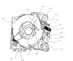
Fig. 1 is a skeleton view, illustrate from the object of photograph comprising of seeing according to the structure of the major part of the optical system equipment of the lens barrel of first embodiment of the invention, wherein lens group folds.
Fig. 2 is a skeleton view, and the major part of the lens barrel of seeing from imaging surface shown in Figure 1 is shown.
Fig. 3 is a perspective schematic view, illustrate from the structure of major part of the optical system equipment that comprises the lens barrel that lens switch cover is wherein closed seen of the object of photograph.
Fig. 4 is a perspective schematic view, and the structure of seeing from imaging surface in the major part of the lens barrel shown in Fig. 3 is shown.
Fig. 5 is a perspective schematic view, illustrate the lens switch of seeing from imaging surface therein cover on open under the photograph state and state that lens group is extended under the structure of major part of lens barrel.
Fig. 6 is a skeleton view, illustrate from imaging surface see under the photograph state and the structure of the lens barrel major part of lens group when extending.
Fig. 7 is a skeleton view, illustrate from the lens group therein seen of the object of photograph be in the 3rd framework, protecting against shock member and four gimbaled layout under the state of folded position, be used for illustrating the 3rd framework that keeps the three-lens group and the operation of protecting against shock member.
Fig. 8 is a skeleton view, illustrate from the object of photograph the 3rd framework, protecting against shock member and the four gimbaled layout seen, be used for that the 3rd framework that keeps the three-lens group is described and be in the operation of the protecting against shock member under the photograph state that lens group stretches out.
Fig. 9 is a vertical sectional view, its in respect to the first half of optical axis and Lower Half, be illustrated under the photograph state that lens group wherein stretches respectively and therein lens group return and remove the major part that lens group under the folding folded state, camera lens keep each camera lens cylinder of framework and lens barrel.
Figure 10 is a schematic front elevation that launches, and is illustrated in the shape that is formed on the cam groove on second rotor under the deployed condition.
Figure 11 is a schematic front elevation that launches, and is illustrated in the shape that is formed on the cam groove on the camcylinder under the deployed condition.
Figure 12 one schematically launches front elevation, is illustrated in the keyway that is formed under the deployed condition on first lining and the shape of cam groove, has wherein omitted helicoid.
Figure 13 one schematically launches front elevation, is illustrated in the keyway that is formed under the deployed condition on the fixed frame and the shape of cam groove, has wherein omitted helicoid.
Figure 14 is a side view, and the structure of the 3rd framework and drive system thereof is shown.
Figure 15 is a skeleton view, and the structure of the 3rd framework and drive system thereof is shown.
Figure 16 is used to illustrate the operation of the 3rd framework for the rear view of the 3rd frame part seen from imaging surface.
Figure 17 A and 17B are skeleton view, illustrate from the object of photograph outward appearance and the structure seen according to the camera of second embodiment of the invention, wherein Figure 17 A illustrates photographic lens wherein and is folded in state in the camera body, and Figure 17 B illustrates wherein, and photographic lens stretches out from camera body or extended state.
Figure 18 is a skeleton view, the outward appearance and the structure of the camera of schematically illustrated Figure 17 A that sees from customer-side and 17B.
Figure 19 is a block scheme, the functional structure of the camera of schematically illustrated Figure 17 A and 17B.
Figure 20 is a decomposition diagram, and the structure of lens barrel part under the state that partly stretches out according to the lens group of the camera of third embodiment of the invention seen from imaging surface and the structure of the camera protecgulum under the semi-closed state of lens switch cover are shown.
Figure 21 is a decomposition diagram, illustrate from the structure under the state shown in Figure 20 seen of the object of photograph.
Figure 22 is a rear view, and the structure of the camera protecgulum of seeing from imaging surface of therefrom removing inner cap is shown.
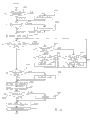
Figure 23 is a process flow diagram, the lens switch cover is shown wherein operates the state of off-position from open position.
Figure 24 A is a form, and the replacement order of lens barrel is shown.
Figure 24 B is the sequential chart of H signal.
Figure 25 is a sequential chart, is illustrated in the order of depositing under the lens switch cover closing state wherein.
Figure 26 is a process flow diagram, and the zoom order is shown.
Figure 27 is a sequential chart, and the state of taking from the wide-angle to the long distance is shown.
Figure 28 is a sequential chart, and the state that photographs wide-angle from long distance is shown.
Embodiment
Now with reference to these accompanying drawings the preferred embodiments of the invention are elaborated.No matter where, in these drawing and description, use identical Reference numeral to refer to same or analogous part.But the present invention is not limited to these embodiments.Within the scope of the invention, can suitably change arbitrary structures described below and material.
Fig. 1 to 16 and 20 illustrates first embodiment according to lens barrel of the present invention.
In Fig. 1 to 16 and 20, lens barrel comprises fixed frame 21 with stationary cylinder 21a, is installed in telescopic barrel assemblies or telescopic cylinder on the fixed frame 21, and is arranged on a plurality of lens group in the telescopic cylinder.Telescopic cylinder can move along the optical axis X of a plurality of lens group and be folding.
These lens group for example comprise first lens group (movable camera lens), 11, second lens group (movable camera lens) 12, three-lens group (movable camera lens) 13 and four-barrel group (movable camera lens) 14, and they are arranged on (referring to Fig. 9) in the telescopic cylinder.
Telescopic cylinder comprises at least one movable cylinder.In this embodiment, telescopic cylinder comprises for example first rotor 22, first lining 23, second rotor 24, second lining 25, camcylinder 26, linear movement cylinder 27 and is used to keep the 3rd framework 31 (referring to Fig. 5 and 8) of three-lens group (retractable lens) 13.As described below, first rotor, 22 grades with a plurality of lens group 11 to 14 relative to each other along axis movement.Replace telescopic cylinder, can use arbitrary shape or structure.For example, the rod or the bar that can adopt a plurality of peripheral intervals to open, and need not be confined to the drum of telescopic cylinder.
As shown in Figure 9, first, second, third and four- barrel group 11,12,13 and 14 from the object (not shown) of photograph begin sequentially to locate and be arranged on the optical axis X.Shutter/aperture retaining assembly (aperture stop unit) 15 is arranged between second lens group 12 and the three-lens group 13.First, second, third and four- barrel group 11,12,13 and 14 and shutter/aperture retaining assembly 15 constitute at telescopic cylinder and when optical direction moves, can move along optical axis direction.
For this lens barrel being used for for example digital camera etc. of imaging device or optical device, as described below, for example will comprise that the solid-state image sensing device 16 of CCD (charge-coupled image sensor) etc. is arranged on the sidepiece of the imaging surface of contiguous four-barrel group 14.
With reference to Fig. 9, first lens group 11 is installed on first framework 17, and in case of necessity cover glass 18 and low-pass filter 19 is arranged near the image receiving surface of CCD 16.
In general, as shown in Figure 9, the structure of lens barrel is that first to fourth lens group can be moved between the extended extended position D at the folding position in leaving stationary cylinder 21a in (S) with from stationary cylinder 21a, thereby the realization zoom, and at least one lens group of first to fourth lens group can be withdrawn into as the retracted position shown in the R in Fig. 9 from optical axis.In this embodiment, at least one part of three-lens group 13 is passed the through hole that is located among the stationary cylinder 21a and is withdrawn into retracted position from optical axis.
To be described in detail this below.
As described below, first lens group 11 to the four-barrel group 14 has the zoom lens function, and its mid-focal length is variable.First lens group 11 comprises one or more camera lenses, and keeps first framework 17 of first lens group 11 to be fixed on the linear movement cylinder 27 by integral body.
Shutter/aperture assembly 15 comprises shutter and aperture, and be inserted into the cam groove that is used at the shutter/aperture of the cam cylinder 26 shown in Figure 11 with the cam follower that shutter/aperture assembly 15 forms as one, and engage with the linear channel 25a on second lining 25, thereby make shutter/aperture assembly support by the camcylinder 26 and second lining 25.
Shown in Figure 13 A and 13B, fixed frame 21 comprises having the cylindrical part (that is stationary cylinder 21a) that is formed with along the inside surface of the spirality cam groove of axial direction and linear channel.The spirality cam follower that is formed on the external peripheral surface of bottom of first rotor 22 engages with the spirality cam groove shown in Figure 13 C, and the key part that is formed on the inside surface of bottom of first lining 23 engages with the linear channel of the fixed frame of fixed frame 21.The inside surface of first rotor 22 is formed with the guide groove that transversely extends in the plane of optical axis X.What engage with guide groove is driven member or key, and it forms near its bottom, stretches out from the external peripheral surface of first lining 23, and is used as linear structure.
The inside surface of first lining 23 is formed with along the helicoid of optical axis and linear channel, and other first lining 23 is formed with clearance groove, wherein is inserted with to form near the bottom cam follower that stretches out from the bottom external peripheral surface of second rotor 24.
Helicoid is formed on the external peripheral surface of bottom of second rotor 24, and engages with the helicoid of first lining 23.Forming near the bottom cam follower that stretches out from the external peripheral surface of second rotor 24 engages with linear channel the inside circumference that is formed on first rotor 22 by the clearance groove of the cam follower on first lining 23.Forming the key part of stretching out from the external peripheral surface of the bottom of second lining 25 engages with linear channel on the inner circumferential surface that is located at first lining 23.
The inside surface of second rotor 24 is provided with transversely in the guide groove on the plane of optical axis X, is arranged to the driven member that stretches out from the external peripheral surface of second lining 25 or keyed engagement the guide groove of second rotor 24.Adopt this structure, second lining 25 moves along optical axis X with second rotor 24, and second rotor 24 can rotate with respect to second lining 25 simultaneously.
Be assemblied in camcylinder 26 on the inner peripheral surface of second lining 25 and be constructed such that bump bonding on the external peripheral surface that is formed on the bottom is assemblied on the bottom of second rotor 24 and engages, thereby rotate integratedly with second rotor 24.The inside surface of second lining 25 is provided with transversely in the guide groove on the surface of optical axis X, and the driven member or the key that are located on the external peripheral surface (front side) of camcylinder 26 engage with cam groove.Adopt this structure, camcylinder 26 moves along optical axis X with second lining 25, can rotate with respect to second lining 25 simultaneously.
The bottom of linear movement cylinder 27 is inserted between second rotor 24 and second lining 25, and cam follower forms that the external peripheral surface from linear cylinder cylinder 27 stretches out near the bottom, and cam follower engages with cam groove in the inner circumferential surface that is formed on second rotor 24.On the inner circumferential surface of linear drive drum 27, be formed with linear channel, and the key part that is formed on the external peripheral surface of second lining 25 engages with linear channel along axial direction.
On the neighboring of the bottom of first rotor 22, be formed with gear parts, this gear parts and the one or more gear engagement that drive by zoom motor 51, thereby make the driving force of zoom motor 51 give gear by these gear transmission, thus, first lens group 11, second lens group 12 and shutter/aperture assembly 15 are according to predetermined mode zoom.Zoom motor comprises DC motor commonly used in this embodiment.
Simultaneously, the cam groove that illustrates on second rotor 24 of Figure 10 engages with cam follower on the linear movement cylinder 27.
The cam groove that Figure 11 illustrates respectively on the camcylinder 26 keeps the cam follower on the framework to engage with the camera lens of second lens group 12, and the cam groove of camcylinder 26 engages with the cam follower of shutter/aperture assembly 15.
The cam groove that Figure 12 illustrates respectively on first lining 23 engages with the cam follower of second rotor 24, and the key fillister joint on the straight groove on first lining 23 and second lining 25.
The linear channel that Figure 13 illustrates respectively on the fixed frame 21 partly engages with the key of first lining 23 of fixed frame, and the cam groove of fixed frame 21 engages with the cam follower of first rotor 22.
In general, be in the position of close fixed frame and the rotor that is arranged on the outermost circumference and be screwed on the fixed frame by helicoid usually, and helicoid constitutes rotor is moved with respect to fixed frame with constant speed.Therefore, rotor this rotor from collapsible position through too short focal length/wide-angle position moves to the process of long-focus/long distance camera site gradually, be in half extension state that leaves fixed frame at short focal length/wide-angle position.
On the contrary, in said structure, first rotor 22 of close fixed frame 21 is by the fixed frame screw-threaded engagement of spirality cam groove and fixed frame 21, and simply spiral connects.First rotor 22 is by being driven into short focal length/wide-angle position and moving to maximum projecting position fully from collapsible or folding position.Afterwards, as shown in figure 13, because the reference object side end of cam groove and the end face of fixed frame are arranged abreast,, and can not move along optical axis X so first rotor 22 rotates in constant position during being driven into long-focus/long distance camera site from short focal length/wide-angle position.
In addition, three-lens group 13 is left optical axis X in the folded position withdrawal, and wherein lens group is folded in the fixed frame 21, as shown in Figure 9.Move on the optical axis X in the extended position place of lens group three-lens group 13.
Along with first rotor 22 moves from the folding position to short focal length/wide-angle position, this cylinder extends towards the photograph object, rotate at the commitment of extracting action out simultaneously, and when cylinder arrives maximum projecting position, be located on the fixed frame 21 and comprise that for example the zoom position detecting device of reflective optical system, Photo Interrupter, leaf switch etc. produces the zoom position reference signal.Therefore, when the zoom position reference signal produces, arrive maximum projecting position because can determine first rotor 22, so can begin to make the 3rd framework 31 to move on the optical axis X.Therefore, by will extracting out fully near first lining 23 and first rotor 22 of fixed frame when extending the step early of action, thereby can guarantee in advance to be used between second lens group 12 and four-barrel group 14 is inserted into space among the optical axis X with three-lens group 13.
As described below, in case first rotor 22 arrives maximum projecting position, then the zoom position reference signal produces, the space of guaranteeing to be used to insert the three-lens group, and the insertion three-lens group that will begin in a minute.Therefore, can shorten time more from the collapsible position when the power connection to short focal length/wide-angle position.
As mentioned above, regracting three-lens group 13 remains on the 3rd framework 31 or the retractable lens maintenance framework.The 3rd framework 31 keeps three-lens group 13 at the one end, and the 3rd group of capstan 32 that the other end of the 3rd framework 31 is extended by the optical axis with three-lens group 13 substantially parallelly support, thereby can rotate and slide along the 3rd group of capstan 32.The 3rd framework 31 can around the 3rd group of capstan 32, therein as shown in Figure 8 under the photograph state three-lens group 13 is set on the optical axis desired location and wherein as shown in Figure 2 three-lens group 13 take from long distance between the retracted position that cylinder is retracted into fixed frame 21 and rotate.
Near the three-lens group 13 on the sidepiece of the pivoting end that is positioned at the 3rd framework 31, the crank-like sweep, retainer 31a (Figure 15) and the shading band 31b that are used between the sidepiece of the sidepiece of rotation and support section, distinguish the position of three-lens group 13 along the direction parallel with capstan are arranged on the rotation end, to stretch out towards the rotation end basically from sweep.
Aspect optical property, for the focal length that extends under the long distance shooting state, the position of three-lens group 13 under the long distance shooting state is the extended position of more close reference object.But, the possible amount of exercise of the 3rd framework 31 by to lens barrel restriction under folded state along the length of optical axis X determine.Can be by setting the position that is used to keep the three-lens group by being in the 3rd framework 31 of the position of close reference object, thus make the focal length maximization under the long distance shooting state.But, if retainer 31a along the set positions of optical axis in the position identical substantially with three-lens group 13, then the length of the secondary guide shaft 33 of the 3rd framework is longer, and lens barrel becomes bigger in the size of folded position.Therefore, retainer 31a need be arranged on the side of focal position, and the 3rd framework 31 is formed the shape with crank-like sweep.
Simultaneously, the 3rd framework 31 can be formed by two parts, and in this case, one is the member with crank-like sweep, and another is the member that is used to keep three-lens group 13.These two parts are operation integratedly by being fixed together.
As shown in Figure 14 A and 14B, the 3rd framework inner threaded member 35 that is screwed on the 3rd group of lead screw 34 is arranged on from the nearest position of the image surface of CCD under the retracted mode of the 3rd framework 31 withdrawals.Under this state, compression torsion spring 37 is subjected to complete load or compression, is seen as clockwise moment thereby apply from the lens barrel front to the 3rd framework 31 always.
The cylindrical external peripheral surface that is subjected to support section 31g that is located on the capstan 32 that is used for the 3rd framework 31 is provided with step part 31c, and the cam portion 31e that is arranged in the step part 31c and is formed by the inclined-plane, shown in Figure 14 A.
Under this state, the 3rd framework CD-ROM drive motor 52 from see previously as lens barrel clockwise rotate the time, the 3rd group of lead screw 34 clockwise rotates by the gear mechanism that comprises gear 71 to 74, and the 3rd framework inner threaded member 35 is moved towards reference object along optical axis X.At this moment, the 3rd framework 31 clockwise rotates under the effect of moment forces of compression torsion spring 37, and cam portion 31e engages with the first adjacent part 35a on being located at the 3rd framework inner threaded member 35.
Afterwards, when the 3rd framework inner threaded member 35 from the motion of the nearest position of reference object the time, the light of the 3rd framework 31 blocks the position that band 31b moves to the 3rd framework Photo Interrupter 38, as the device that is used to detect three-lens group 13 positions, the 3rd framework Photo Interrupter 38 produces reference signals thus, and this signal is in from L or low level to the scope of H or high level.Therefore, the position of three-lens group 13 is controlled from the reference signal of the 3rd framework Photo Interrupter 38 by the step-by-step counting basis.
From this state, when the 3rd framework inner threaded member 35 moves to the withdrawal starting position B of the 3rd framework 31, shown in Figure 14 A, the 3rd framework 31 further clockwise rotates, retainer 31a begins shown in Fig. 8 and 16A and secondary guide shaft 33 adjacency of the 3rd framework, therefore determines the 3rd position of framework 31 on optical axis.Therefore, finish three-lens group 13 to the close operation of optical axis.At withdrawal B place, starting position, the 3rd framework 31 can move towards retracted position S.
Simultaneously, the 3rd framework Photo Interrupter 38 shown in the shading band 31b Occlusion Map 16A, thus can confirm that the 3rd framework 31 is in withdrawal starting position B.When the 3rd framework inner threaded member 35 moved to withdrawal starting position B shown in Figure 14 A, the first adjacent part 35a of the 3rd framework inner threaded member 35 contacted with the preceding bonding part 31d of the step part 31c of the 3rd framework 31.Also have, the step part 31c of the 3rd framework 31 has preceding bonding part 31d and the cam portion 31e that forms with the 3rd group of plane that capstan 32 is vertical substantially.
The 3rd framework 31 is subjected to being located at the 3rd group of compression torsion spring 37 bias voltages on the capstan 32 to move towards the direction transverse to optical axis always, that is to say, from the retracted position to the optical axis and along the direction of optical axis, that is to say the fixed head 81 on next door from the reference object to the imaging surface.
In addition, as shown in Figure 14B, fixed frame 21 and the part that contacts of compression torsion spring 37 comprise the step 37a of the concave portions that forms an end that is used to insert compression disc spring 37, are used for preventing to compress the center that torsion spring obviously departs from the 3rd group of capstan 32.
Next, when the 3rd framework inner threaded member 35 moves to short focal length/wide-angle position for example at the wide-angle position W shown in Figure 14 A, because the first adjacent part 35a of the 3rd framework inner threaded member 35 is pressing preceding bonding part 31d, the 3rd framework 31 can move to wide-angle position along optical axis X towards reference object.
And, when the 3rd framework inner threaded member 35 is arranged between withdrawal starting position B and the long distance camera site T, as shown in figure 14, because the 3rd framework 31 is pushed towards imaging surface along optical axis by compression torsion spring 37 always, so the have living space that produces between the 3rd group of lead screw 34, the 3rd framework inner threaded member 35 and fixed head 81 is towards imaging surface, the 3rd framework 31 can be guaranteed the positional precision along optical axis direction.
The 3rd framework inner threaded member 35 is screwed on the 3rd group of lead screw 34 that is provided with optical axis substantially parallelly.The 3rd framework inner threaded member 35 except with the first adjacent part 35a that the above-mentioned preceding bonding part 31d or the cam portion 31c of the 3rd framework 31 engage also comprise anti-rotation teat 35b.
Anti-rotation teat 35b is fitted into slidably with optical axis and is formed on abreast in the guide groove on the cylindrical part of fixed frame 21, as the anti-rotation device that is used to prevent that the 3rd framework inner threaded member 35 from rotating together along with the rotation of the 3rd lead screw 34.In other words, because prevent 35 rotations of the 3rd framework inner threaded member by the anti-rotation teat 35b in the guide groove that is assembled to fixed frame 21, so the 3rd framework inner threaded member 35 moves upward in front and back along optical axis by the rotation of the 3rd lead screw 34.
As institute among Figure 14 A in detail shown in, when the 3rd framework inner threaded member 35 begins further when imaging surface (left side in the figure) moves from the withdrawal starting position B shown in Figure 14 A, the 3rd framework inner threaded member 35 engages with the cam portion 31e of the step part 31c of the 3rd pilot set fixed frame 31.
The 3rd framework 31 contacts with fixed head 81 by the clockwise biasing force of compression torsion spring 37, and the 3rd framework 31 overcomes the clockwise biasing force that is applied by compression torsion spring 37 and rotates counterclockwise, and therefore can make 31 withdrawals of the 3rd framework.
On the other hand, the 3rd inner threaded member 35 by the 3rd group of lead screw 34 backward rotation or rotate counterclockwise when long distance camera site T moves to withdrawal starting position .B through wide-angle position W, because the first adjacent part 35a of the 3rd framework inner threaded member 35 engages with the preceding bonding part 31d of the step part 31c of the 3rd framework 31, so the 3rd framework 31 moves gradually to guide to imaging surface from reference object, simultaneously in the position on optical axis that keeps towards the biasing force of optical axis with under the partial pressure of imaging surface being limited by the secondary guide shaft 33 of the 3rd framework.
Simultaneously, when the 3rd framework inner threaded member 35 arrives withdrawal starting position B, bottom face 31f and fixed head 81 adjacency, the 3rd framework inner threaded member 35 contacts with the spaced apart setting of preceding bonding part 31d and with the cam portion 31e of step part 31c.
The 3rd framework inner threaded member 35 from withdrawal starting position B in folding position S motion, the cam portion 31e sliding contact of the second adjacent part 35c of the 3rd framework inner threaded member 35 and the step part 31c of the 3rd framework 31 and overcome by the rotation biasing force that applies of compression torsion spring 37 the 3rd framework 31 is rotated, the 3rd framework 31 moves to folding position S from the position on the optical axis thus.The folding position S of the 3rd framework 31 is corresponding to such position, and it is producing reference signal in H to L scope and counts towards imaging surface motion predetermined pulse after producing from the 3rd framework Photo Interrupter 38 in this position.After the 3rd framework 31 moved to folding position S, first lens group 11, second lens group 12 and shutter/aperture assembly 15 moved to collapsible or the folding position.
In this embodiment, before the 3rd framework 31 moves to folding position S, be used to keep the 4th framework 41 of four-barrel group 14 at first to move to the folding position.First folding position of the 4th framework 41 is corresponding to such position, and it is producing from the 4th group of reference detector or the 4th group of Photo Interrupter 47 in this position in H to L scope counts towards imaging surface motion predetermined pulse after depositing reference signal.After the 4th framework 41 arrives first folding position, begin the deposit operation of the 3rd framework 31.
That is to say that the 3rd framework inner threaded member 35 begins towards imaging surface motion predetermined pulse counting from the reference signal of depositing from H to L that is produced by the 3rd framework Photo Interrupter 38 (referring to Figure 16 A), and finishes the deposit operation of the 3rd framework 31.After the deposit operation of the 3rd framework 31 is finished, first rotor 22 be arranged on first rotor 22 and first lining 23 in structure member etc. be stored before the 3rd framework 31 contacts.This causes first rotor, 22 grades to deposit under situation about can not interfere with the 3rd framework 31.
Can be by counting the position of setting first rotor 22 etc. by comprising the pinion wheel on the output shaft that directly is mounted to zoom motor 51 and having coder structure and for example be arranged on driving pulse that the zoom count detector of the first and second framework Photo Interrupter 51a the pinion wheel near produces.
Simultaneously, though the DC motor is detected by the detecting device that comprises scrambler and Photo Interrupter as the drive source that makes 22 motions of first rotor and the activation point of first rotor 22, but in the above-described embodiments, by replacing whole said structure can realize similar function the impulse motor structure.
In order to prevent the 3rd framework 31 other parts of collision, as especially as shown in Fig. 2 and 7, protecting against shock member 36 is supported on the fixed frame 21 near the 3rd group of capstan 32 rotationally, and comprises the rotating part at an end place that is located at the protecting against shock member and engage teat 36a.Protecting against shock member 36 is moved towards optical axis X so that engage teat 36a by bias voltages such as springs always.
When the 3rd framework 31 was arranged on folded position, protecting against shock member 36 overcame the biasing force release of spring by the revolving force of the 3rd framework 31, and is offset to the 3rd framework 31 outsides (specifically referring to Fig. 2 and Fig. 7).
When the 3rd framework 31 rotates and is arranged on the optical axis, removed engaging of protecting against shock member 36 and the 3rd framework 31, and make it to rotate so that engaging teat 36a stretches out towards optical axis X by biasing force, make joint teat 36a stretch out thus from the inside surface of the fixed frame of fixed frame 21.At this moment, except first rotor 22 and first lining 23, all are arranged on second rotor 24, second lining 25, camcylinder 26 and linear movement cylinder 27 on the reference object side with respect to the extended position that engages teat 36a.Therefore, engaging teat 36a is arranged to inwardly stretch out (specifically referring to Fig. 5, Fig. 6 and Fig. 8) from each the neighboring of bottom of first rotor 22 and first lining 23.
Adopt this structure, even rotate first rotor 22 by compulsion with hand and make it to move under the situation of folding position operating personnel, protecting against shock member 36 at first contacts with first rotor 22.Therefore, because can not more move towards imaging surface along the position of optical axis than protecting against shock member 36 in the bottom of first rotor 22, contact with the 3rd framework 31 so prevent first rotor 22.Therefore, can realize preventing that the 3rd framework 31 is owing to strong external force ruptures, damage etc.
In addition, correctly after folding position motion, first rotor 22 can at first move to the folding position at the 3rd framework 31.Therefore, at movable cylinder for example under the use or photograph state of the lens barrel that extends therein of first rotor, 22 grades, when the whereabouts by lens barrel etc. applies very big pressure on the front end of lens barrel etc., the joint teat 36a of protecting against shock member 36 engages with first rotor 22 and first lining 23, therefore and prevent that first rotor 22 and first lining 23 (and second rotor 24, second lining 25, camcylinder 26 and linear movement cylinder 27) from further withdrawing towards three-lens group 13, thereby prevented that the 3rd framework 31 and three-lens group 13 are impaired.
The 3rd group of lead screw 34 by the 3rd framework CD-ROM drive motor 52 along rotating with inverse direction forward.The rotation of the 3rd framework CD-ROM drive motor 52 passes to the 3rd group of lead screw 34 by the gear 71,72,73 and 74 that is disposed in order.
Next, with reference to Fig. 7,8,20A and 20B the drives structure of four-barrel group 14 is described.
Four-barrel group 14 as the amasthenic lens that lens group is focused on is kept by the 4th framework 41 in the illustrated embodiment, shown in Figure 20 A and 20B.The 4th framework 41 comprises: sleeve part 41a wherein is equipped with the 4th framework capstan 44 that is provided with and is fixed to lens barrel bottom 82 with optical axis abreast; And anti-rotation part 41b, wherein be equipped with the secondary guide shaft 42 of the 4th framework that is provided with abreast and is fixed to optical axis on the lens barrel bottom 82, be used for limiting the rotation of the 4th framework 41.Adopt this structure, the 4th framework 41 can freely move along the 4th framework capstan 44 or optical axis.The 4th framework CD-ROM drive motor 53 that is made of step motor is used as the drive source that drives the 4th framework 41 in the embodiment illustrated.Be provided with the 4th framework lead screw 45 on the output shaft of the 4th framework CD-ROM drive motor 53, it is screwed into the threaded hole that is located in the 4th framework inner threaded member 46.
The 4th framework 41 has the opening that is used to insert the 4th framework inner threaded member 46.This opening have be used for a side of imaging surface with at the bonding part 41c that engages with respect to the 4th framework inner threaded member 46 on the vertical plane of optical axis.By allow the 4th framework 41 by the 4th framework spring 43 bias voltages to reference object, make the 4th framework 41 always engage with the 4th framework inner threaded member 46.
The 4th framework inner threaded member 46 has radially-protruding teat 46a.This teat 46a is bonded among the duct 41d of opening one side that is located at the 4th framework inner threaded member 46 that is used for inserting the 4th framework 41, thereby the rotation of the 4th framework inner threaded member 46 is stopped.
Like this, when the 4th framework CD-ROM drive motor 53 that drives as step motor, the 4th framework lead screw 45 rotates, and the 4th framework inner threaded member 46 is being moved forward with on the inverse direction along the axis or the optical axis X of the 4th framework lead screw 45.Because the 4th framework 41 engages with the 4th framework inner threaded member 46, thus the 4th framework 41 along with the motion of the 4th framework inner threaded member 46 along axis movement.In this case, though the 4th framework lead screw 45 is formed on the output shaft of the 4th framework CD-ROM drive motor 53, but can be by constituting the 4th framework CD-ROM drive motor 53 and the 4th framework lead screw 45 respectively and be connected them, thereby the 4th framework lead screw 45 be rotated by gear etc.
The 4th framework 41 is provided with the shading piece 41e that is used for covering the light-path that is located at the 4th group of Photo Interrupter 47 on the lens barrel bottom 82, and this shading piece 41e can respond the motion shading of the 4th framework 41 or allow light pass the light-path of the 4th group of Photo Interrupter 47.In this case, by making shading piece be set to the moment of light by state when beginning to activate the pulse waveform of any number of pulses as the reference position, from the reference position and the 4th framework CD-ROM drive motor 53 is rotated, thereby the 4th framework 41 is moved in the pre-position from the shading state.
Simultaneously, the 4th framework 41 has concave portions 41f, this part be located in the framework neighboring and the shading band 31b that allows the 3rd framework 31 as Photo Interrupter towards axis movement to avoid and the 4th framework 41 is interfered, the amount of exercise of the 4th framework 41 can be increased thus, and focusing range can be enlarged.And, as mentioned above, between the 4th framework 41 and the 4th framework inner threaded member 46, there is the gap, but can the 4th framework 41 bias voltages be accurately controlled the position of the 4th framework 41 along optical axis direction to reference object always by utilizing the 4th framework spring 43 along optical axis direction.
Control the folding position of first lining 23, first lens group 11, second lens group 12, shutter/aperture assembly 15 and first rotor 22 according to the zoom position reference signal that is produced by the zoom position detecting device that comprises reflective optical system of being arranged in the fixed frame 21 etc.That is to say, deposit reference signal after the variation of H to L zoom position occurring, by by the predetermined pulse counting of the driving pulse that produces as the pinion wheel of scrambler and near the zoom count detector of pinion wheel setting, they are moved towards the plane of delineation, thereby finish deposit operation.
In depositing process, the 4th framework 41 is arranged on aforesaid first folded position, and when first rotor 22 moved to the folding position, the distal most surface of first rotor 22 or first lining 23 contacted and pushes the 4th framework 41 to make it finally to move to second folding position with the 4th framework 41.
By this operation, even occur under the situation of variation in the installation site of the 4th group of Photo Interrupter 47 along optical axis direction, the 4th framework 41 also can accurately move to the folding position, and need not complicated adjusting.Owing to be formed on engaging space in the 4th framework 41 along the length of optical axis direction thickness, so can finish this operation greater than the 4th framework inner threaded member 46.
Be used to make the zoom motor 51 of first lens group 11, second lens group 12 and shutter/aperture assembly 15 motions to constitute by aforesaid DC motor in the illustrated embodiment, the 4th framework CD-ROM drive motor 53 that is used to drive the 3rd framework CD-ROM drive motor 52 of three-lens group 13 and is used to drive four-barrel group 14 constitutes the employing impulse motor usually, for example drives to realize mainly being moved by first to the three-lens group 11-13 suitable zoom that carries out and main adequate focusing of being undertaken by four-barrel group 14 is moved in the mode as software with mutually combining.
Here will the driving control system of the lens group that is used to constitute lens barrel be elaborated.
Driving control system shown in Figure 21.This driving control system comprises CPU (central processing unit) (CPU) 501, motor driver 502, the first and second framework DC motors 503, first aperture retaining motor 504, second aperture retaining motor 505, fast door motor 506, the 3rd framework impulse motor 507, the 4th framework impulse motor 508, the first and second framework Photo Interrupters 509, the first and second framework reflective optical systems 510, the 3rd framework Photo Interrupter 511, the 4th framework Photo Interrupter 512, the first and second framework Photo Interrupter driving circuits 513, the first and second framework reflective optical system driving circuits 514, the 3rd framework Photo Interrupter driving circuit 515 and the 4th framework Photo Interrupter driving circuit 516.
CPU provides instruction to motor driver 502, for example motor driver 502 is carried out selection, the driving voltage of initial setting, CD-ROM drive motor, setting of driving direction etc.Motor driver 502 is according to the motor system that keeps off motor 506, fast door motor 506, the 3rd framework impulse motor 507, the 4th framework impulse motor 508 etc. from the instruction control first and second framework DC motors 503, first aperture retaining motor 504, second aperture of CPU 501.
The first and second framework DC motors 503 drive first and second lens group 11 and 12.Usually, first and second lens group 11 and 12 relative to each other drive in response to the driving of the first and second framework DC motors 503 discretely by cam mechanism.First aperture retaining motor 504 and second aperture retaining motor 505 constitute the aperture retaining of driving shutter/aperture assembly 15.Fast door motor 506 drives the shutter of shutter/aperture assembly 15.The 3rd framework impulse motor 507 drives three-lens group 13.The 4th framework impulse motor 508 drives four-barrel group 14.
The first and second framework Photo Interrupter driving circuits 513, the first and second framework reflective optical system driving circuits 514, the 3rd framework Photo Interrupter driving circuit 515 and the 4th framework Photo Interrupter driving circuit 516 can suitably control in the first and second framework Photo Interrupters 509, the first and second framework reflective optical systems 510, the 3rd framework Photo Interrupter 511 and the 4th framework Photo Interrupter 512 each output signal and the projection electric current (projecting current) degree.
Here following description is used to protect the lens switch cover 62 of lens barrel.
Be arranged under the storage configuration at the lens switch cover 62 shown in Fig. 3 to Fig. 5 and cover the side of first lens group 11, and protect this lens group to pollute or damage avoiding in the face of reference object.Lens switch cover 62 moves in the forward and backward directions transverse to optical axis ground under 63 effects of lens switch cover drive system.Fig. 3 and 4 illustrates lens switch cover 62 closing state, and Fig. 5 illustrates the state that lens switch cover 62 is almost opened.Lens switch cover 63 drives lens switch cover 62 by operating between off-position (Fig. 3 and 4) and the open position (than in the position of the position shown in Fig. 5 further from optical axis) of lens switch cover executive component (referring to the lens switch cover executive component 301 in Figure 17 A).Lens switch cover drive system 63 can be at the off-position place along closing direction and in open position along opening direction bias voltage lens switch cover 62.
Therefore, when opening direction and drive the lens switch cover 62 be under the closed condition, lens switch cover 62 semi-automatically moves to open mode during through the precalculated position at lens switch cover 62.Also have, attempting when open mode is closed lens switch cover 62, lens switch cover 62 semi-automatically moves to closed condition during through the precalculated position at lens switch cover 62.Position under needn't requiring in off position is identical with the precalculated position under open mode; On the contrary, preferably lens switch covers on the hysteresis characteristic that has in the motion to a certain degree, to finish the smooth operation of lens switch cover 62.
Lens switch cover control is arranged on the side of fixed frame 21 along the direction of opening lens switch cover 62 with 61 so that can slide along the direction of optical axis, and in case of necessity under the effect of spring etc. towards the reference object bias voltage.Under storage configuration, the lens switch cover control that forms curved shape is with 61 the bonding part and the bottom margin surface engagement of first rotor 22 and first lining 23, and therefore the biasing force that overcomes spring does not contact with lens switch cover 62 towards the imaging surface bias voltage.Under use or photograph state, lens switch cover 62 leaves corresponding lens group and fixed frame thereof fully.Under this state, lens switch cover control is disengaged with the joint of 61 bonding part, therefore the control of lens switch cover with 61 under the effect of biasing force towards the reference object bias voltage, enter into the passage of lens switch cover 62 then in the lens switch cover intercepting part of far-end.
Under this state, so that lens barrel when moving to the folding position, lens switch cover 62 may be run into lens barrel when promptly operating lens switch cover 62.But, owing to intersect with the lens switch cover intercepting part of 61 the far-end passage with lens switch cover 62 in lens switch cover control, thereby prevent that lens switch cover 62 from entering into the moving conduit of lens barrel.When corresponding lens group is deposited and is finished storage configuration, the bottom margin of first lining 23 and first rotor 22 surface and the lens switch cover control that forms curved shape engage with 61 bonding part, thereby overcome biasing force (energize) are encouraged towards imaging surface in the bonding part.Therefore, can make lens switch cover 62 move to the front portion of lens barrel, therefore lens switch cover 62 correctly is set to make-position.Adopt this mode, can prevent effectively in camera lens cylinder that keeps lens group and the interference between the lens switch cover 62.
<actuation sequence 〉
With reference to Figure 22 the actuation sequence of above-mentioned driving control system is described below.
By opening lens switch cover 62, become L from the lens switch cover switching signal of lens switch cover switch (not shown) from H, and the initial setting of beginning lens barrel.Simultaneously, operate lens switch cover switch, can open the lens switch cover by the operation of lens switch cover switch simultaneously by adopting mechanical system to open lens switch cover 62 by (not shown) such as control lever.Thereby carrying out this initial setting makes motor driver 502 carry out initialization CD-ROM drive motor system, and the initialization of the first and second framework Photo Interrupters 509, the first and second framework Photo Interrupters 510, the 3rd framework Photo Interrupter 511 and the 4th framework Photo Interrupter 512, by the first and second framework Photo Interrupter driving circuits 513, the first and second framework reflective optical system driving circuits 514, the 3rd framework Photo Interrupter driving circuit 515 and the 4th framework Photo Interrupter driving circuit 516, as position detecting device corresponding to the position.
Representing under the situation of folding position that by the first and second framework Photo Interrupters 509, the 3rd framework Photo Interrupter 511 and the 4th framework Photo Interrupter 512 detected results the first and second framework DC motors 503 are applicable to and are driven into wide-angle position.Detect the amount of being driven of the first and second framework DC motors 503 by the momental first and second framework Photo Interrupters 509 that are used to detect first and second lens group.Amount of exercise detects by the marginal portion counting by the first and second framework Photo Interrupters, 509 pulse signals (PI signal).
And then set during the actuating after activating the first and second framework DC motors 503, between this period of energization, thereby driving voltage is lower than the input current that fixed voltage prevents the DC motor.After between this period of energization, finishing, make driving voltage increase to fixed voltage.
By CPU 501 set and then begin to activate be used to after the first and second framework DC motors 503 to monitor lens switch cover switch or lens switch cover SW during, and the state of monitoring lens switch cover switching signal.During monitoring, if the open mode of lens switch cover switching signal indication camera lens switch cover, then the fast door motor by being used to drive shutter 50 is set at shutter fully and opens.Then, by first and second apertures retaining motor 504 and 505 the aperture retaining is arranged under the medium constrained state.
In this embodiment, though the aperture retaining is set under the medium constrained state, it can be set under open mode or the full open position.
Next, drive four-barrel group 14 in advance by the 4th impulse motor 508.By realizing the driving in advance of four-barrel group 14, can reduce from beginning to drive the T.T. of first and second lens group to the driving of finishing last four-barrel group 14.And, by the pulsed frequency of the 4th framework impulse motor 508 in it drives in advance is set at than slower under the driven state, moment be can when driving, strengthen, and four-barrel group and other parts interference prevented.
Simultaneously, the amount that drives by the 4th framework impulse motor 508 of four-barrel group is set at and makes third and fourth lens group relative to each other interfere.
When four-barrel group 14 driving is finished in advance the time, the first and second framework reflective optical systems 510 such as are set at reference position to be detected.Reference position signal becomes the reference position or the HP position of first and second lens group 11 and 12 from the place that H becomes L.When reference position that detects first and second lens group 11 and 12 or HP position, the positional information of first and second lens group 11 and 12 is reset.By counting the signal (PI signal) of similar pulse according to positional information, obtaining the amount of exercise that first and second lens group arrive wide-angle position, thereby control the motion of first and second lens group by the first and second framework Photo Interrupters 509.Preestablish this wide-angle position, but, can change this wide-angle position by being stored on the nonvolatile memory and rewriteeing.
Arrive during the certain pulses before the wide-angle position to stopping control period, reduce driving voltage by afterpulse number according to the distance wide-angle position, thus the excess of stroke can reduce to arrive wide-angle position the time.If first and second lens group are then braked control so that first and second lens group are stopped by arriving wide-angle position by the first and second framework Photo Interrupters, 509 counting PI signals.Overshoot during the braking is counted, thereby determined the final position of first and second lens group 11 and 12.
And when reference position that detects first and second lens group 11 and 12 or HP position, the 3rd framework impulse motor 507 is along the driving initialization of wide-angle position direction, to adopt first and second lens group 11 and 12 control three-lens groups 13.By will being set at than higher in driven or faster, thereby can reduce the driving time of three-lens group 13 in the pulsed frequency in driving the 3rd group pulse motor.
Three-lens group 13 is waited for by the 3rd framework Photo Interrupter 511 and is detected the reference position.Become the reference position or the HP position of three-lens group 13 from the place that L becomes H by the reference position signal of the 3rd framework Photo Interrupter 511 operation or HP signal.When detecting reference position or HP position, the positional information of three-lens group 13 is reset.Three-lens group 13 is carried out pulsed drive by the 3rd framework impulse motor 507 according to positional information, to obtain the amount of exercise that three-lens group 13 arrives wide-angle position.Preestablish wide-angle position, but can for example rewrite among the EEPROM etc. and with it and change it by it being stored in nonvolatile memory.
In addition, the final stop position of three-lens group 13 becomes the position of the excess of stroke of having considered first and second lens group 11 and 12.That is to say, add overshoot, so the stop position of three-lens group 13 also is in the wide-angle position that has added the α under the excess of stroke situation of considering first and second lens group 11 and 12 because the stop position of first and second lens group 11 and 12 is a wide-angle position.Thereby by carrying out the linear numerical value that obtains α that calculates according to umber of pulse between the zoom position of first and second lens group 11 and 12, umber of pulse and overshoot between the zoom position of three-lens group 13.Zoom position is in the part of (between W and T) 16 five equilibriums between wide-angle position and the long distance camera site.
If finish the driving of first and second lens group 11 and 12, then detect the reference position or the HP position of three-lens group 13, and with the more umber of pulse of three-lens group 13 drive ratio certain pulses numbers, beginning is along the driving of the 4th framework impulse motor 508 of wide-angle infinite locality.If do not finish the driving of first and second lens group 11 and 12, perhaps begin not the more umber of pulse of three-lens group 13 drive ratio certain pulses from the reference position, then finish the driving of first and second lens group 11 and 12, and set waiting status up to beginning from the reference position with the more umber of pulse of three-lens group 13 drive ratio certain pulses.When the driving of not finishing first and second lens group 11 and 12 and when having driven the 4th framework impulse motor 508, drive these three motors simultaneously to increase current drain.Therefore, in this embodiment, have only third and fourth lens group to be driven simultaneously.And, when four-barrel group 14 was driven before three-lens group 13 in-positions when counting more than certain pulses, between third and fourth lens group 13 and 14, occur interfering.Therefore, after driving three-lens group 13 greater than the certain pulses number, begin the driving of four-barrel group 14.
Four-barrel group 14 is waited for and is detected the reference position by the 4th framework Photo Interrupter 512.In addition, be set at the driving voltage that is lower than driven, thereby can reduce current drain by driving voltage with the 4th framework impulse motor 508.Become the reference position or the HP position of four-barrel group 14 from the place that L becomes H by the reference position signal of the 4th framework Photo Interrupter 512 operation or HP signal.In the reference position that detects the 4th lens combination or during the HP position, the positional information of four-barrel group 14 is reset.Four-barrel group 14 is carried out pulsed drive by the 4th framework impulse motor 508 according to positional information, to obtain the amount of exercise that four-barrel group 14 arrives wide-angle position.This wide-angle position can preestablish, but can for example rewrite among the EEPROM etc. and with it and change it by it being stored in nonvolatile memory.
In this embodiment, as mentioned above and as shown in the sequential chart of Figure 22, can reduce current drain, and the optimization by these motors drives and shortens the time that activates these motors thereby be restricted to two motors by the motor that will drive simultaneously.
Next, with reference to Figure 23 explanation and then beginning to activate the first and second framework DC motors 503 after, monitor lens switch cover switch during in, the situation of the signal of time change lens switch cover switch in off position.If lens switch cover switching signal is changed into closed condition from open mode in during this period, then stop to drive the first and second framework DC motors 503.
Afterwards, begin the first and second framework DC motors 503 are driven with amount of exercise or certain pulses number along the folding position direction.In this case, driving voltage is lower, even and the operation part of lens switch cover the folding position bump against switch, first and second lens group etc. at last, also can prevent to produce fracture and damage.By this control, prevented the interference of first and second lens group and lens switch cover.
[replacement order]
And, if the testing result of first and second reflective optical systems 510 is not folding position (reference position HP, signal L), the testing result of the 3rd framework Photo Interrupter 511 is not folding position (reference position HP, signal H), perhaps the testing result of the 4th framework Photo Interrupter 512 is not folding position (reference position HP, signal H), then carries out replacement and drives in proper order.
Below with reference to Figure 24 replacement is described in proper order.
<for first and second groups of HP signal=H, the 3rd group of HP signal=L, the 4th group of HP signal=L 〉
At first, the replacement operation as first and second lens group 11 and 12 detects the reference position or the HP position of first and second lens group, and makes first and second lens group move to wide-angle position (first and second groups: reset).Next,, detect the reference position or the HP position of four-barrel group 14, and make the four-barrel group move to folding position (the 4th group: deposit) as the deposit operation of four-barrel group 14.
Subsequently, the replacement operation as three-lens group 13 detects the reference position or the HP position of three-lens group 13, and makes the three-lens group move to wide-angle position (the 3rd group: reset).
At last, the replacement operation as four-barrel group 14 detects the reference position or the HP position of four-barrel group 14, and makes the four-barrel group move to wide-angle infinite position (the 4th group: reset).
<for first and second groups of HP signal=H, the 3rd group of HP signal=L, the 4th group of HP signal=H 〉
At first, remove operation as returning of first and second lens group 11 and 12, after detecting reference signal decline, first and second lens group are taken the direction driving and are carried out pulsed drive (first and second groups: return and remove) by certain pulses along long distance.Next,, detect the reference position or the HP position of four-barrel group 14, and make the four-barrel group move to folding position (the 4th group: deposit) as the deposit operation of four-barrel group 14.Subsequently, the replacement operation as first and second lens group 11 and 12 detects the reference position or the HP position of first and second lens group 11 and 12, and makes first and second lens group move to wide-angle position (first and second groups: reset).
Next, the replacement operation as three-lens group 13 detects the reference position or the HP position of three-lens group 13, and makes the three-lens group move to wide-angle position (the 3rd group: reset).At last, the replacement operation as three-lens group 13 detects the reference position or the HP position of four-barrel group 14, and makes the four-barrel group move to wide-angle infinite position (the 4th group: reset).
<for first and second groups of HP signal=H, the 3rd group of HP signal=H, the 4th group of HP signal=L, first and second groups of HP signal=H, the 3rd group of HP signal=H, the 4th group of HP signal=H 〉
At first, remove operation as returning of first and second lens group 11 and 12, after detecting reference signal decline, first and second lens group are along long distance shooting direction driving and by (first and second groups of certain pulses pulsed drive; Return and remove).Next,, detect the reference position or the HP position of four-barrel group 14, and make the four-barrel group move to folding position (the 4th group: deposit) as the deposit operation of four-barrel group 14.If can detect the reference position or the HP position of four-barrel group 14, then, detect the reference position or the HP position of three-lens group 13, and make the three-lens group move to folding position (the 3rd group: deposit) as the replacement operation of three-lens group 13.If can not detect the reference position or the HP position of four-barrel group 14, then because consider that four-barrel group 14 and three-lens group 13 interfere, so carry out the deposit operation (the 3rd group: deposit) of three-lens group 13 in advance.
If finished the deposit operation of three-lens group 13, then carry out the deposit operation (the 4th group: deposit) of four-barrel group 14.If when the depositing of operation three-lens group 13, do not detect the HP position, so because consider that three-lens group 13 and four-barrel group 14 interfere, remove operation as returning of three-lens group 13, three-lens group 13 is taken direction along long distance and is driven (the 3rd group: return and remove) by the certain pulses sum.Afterwards, carry out the deposit operation (the 4th group: deposit) of four-barrel group 14 and the deposit operation (the 3rd group: deposit) of three-lens group 13.
Subsequently, the replacement operation as first and second lens group 11 and 12 detects the reference position or the HP position of first and second lens group 11 and 12, and makes first and second lens group move to wide-angle position (first and second groups: reset).Next, the replacement operation as three-lens group 13 detects the reference position or the HP position of three-lens group 13, and makes the three-lens group move to wide-angle position (the 3rd group: reset).At last, the replacement operation as four-barrel group 14 detects the reference position or the HP position of four-barrel group 14, and makes the four-barrel group move to wide-angle infinite position (the 4th group: reset).
<for first and second groups of HP signal=L, the 3rd group of HP signal=L, the 4th group of HP signal=L, first and second groups of HP signal=L, the 3rd group of HP signal=L, the 4th group of HP signal=H 〉
At first,, detect the reference position or the HP position of four-barrel group 14, and make the four-barrel group move to folding position (the 4th group: deposit) as the deposit operation of four-barrel group 14.Next,, detect the reference position or the HP position of three-lens group 13, and make the three-lens group move to folding position (the 3rd group: deposit) as the deposit operation of three-lens group 13.Then, the replacement operation as first and second lens group 11 and 12 detects the reference position or the HP position of first and second lens group 11 and 12, and makes first and second lens group move to wide-angle position (first and second groups: reset).As the deposit operation of three-lens group 13, detect the reference position or the HP position of three-lens group 13 subsequently, and make the three-lens group move to wide-angle position (the 3rd group: reset).At last, the replacement operation as four-barrel group 14 detects the reference position or the HP position of four-barrel group 14, and makes the four-barrel group move to wide-angle infinite position (the 4th group: reset).
<for first and second groups of HP signal=L, the 3rd group of HP signal=H, the 4th group of HP signal=L, first and second groups of HP signal=L, the 3rd group of HP signal=H, the 4th group of HP signal=H 〉
At first,, detect the reference position or the HP position of four-barrel group 14, and make the four-barrel group move to folding position (the 4th group: deposit) as the deposit operation of four-barrel group 14.If can detect the reference position or the HP position of four-barrel group 14, then as the deposit operation of three-lens group 13, detect the reference position or the HP position of three-lens group 13, and make the three-lens group move to folding position (the 3rd group: deposit).
If can not detect the reference position or the HP position of four-barrel group 14, then because considering four-barrel group and three-lens group 13 interferes, so carry out the deposit operation (the 3rd group: deposit) of three-lens group 13 in advance.If finish the deposit operation of three-lens group 13, then carry out the deposit operation (the 4th group: deposit) of four-barrel group 14.If when the depositing of operation three-lens group 13, do not detect the HP position, then interfere because consider three-lens group 13 and four-barrel group 14, so remove operation as returning of three-lens group 13, drive predetermined pulse counting (the 3rd group: return and remove) so three-lens group 13 is taken direction along long distance.
Afterwards, carry out the deposit operation (the 4th group: deposit) of four-barrel group 14 and the deposit operation (the 3rd group: deposit) of three-lens group 13.Subsequently, the replacement operation as first and second lens group 11 and 12 detects the reference position or the HP position of first and second lens group 11 and 12, and makes first and second lens group move to wide-angle position (first and second groups: reset).Then, the replacement operation as three-lens group 13 detects the reference position or the HP position of three-lens group 13, and makes the three-lens group move to wide-angle position (the 3rd group: reset).At last, the replacement operation as four-barrel group 14 detects the reference position or the HP position of four-barrel group 14, and makes the four-barrel group move to wide-angle infinite position (the 4th group: reset).
[depositing order]
Lens switch cover switching signal is changed into H with the beginning deposit operation by closing lens switch cover 62 from L.Simultaneously, can mechanically close lens switch cover 62 by control lever etc. and operate lens switch cover switch, perhaps can close lens switch cover 62 by the operation of lens switch cover switch.
By the complete closing control of being undertaken by 506 pairs of shutters of fast door motor, the shutter that shutter/aperture is kept off assembly 15 is set under the complete closing state.Next, by undertaken by first and second apertures retainings CD-ROM drive motor 504 and the 505 pairs of aperture retainings intermediate restriction control, the aperture retaining of shutter/aperture retaining assembly 15 is set under the intermediate restriction state.Subsequently, realize the driving of depositing of four-barrel group 14 by the 4th framework impulse motor 508.Beginning with the 4th framework impulse motor 508 after the folding position drives, to set wait so that detect the reference position of the 4th framework impulse motor 508 by the 4th framework Photo Interrupter 512.
From by the reference position signal of the 4th framework Photo Interrupter 512 operation or HP signal from place that H becomes L to the folding position, with amount of exercise pulsed drive the 4th framework impulse motor 508 that can arrive the folding position.The amount of exercise of this arrival folding position preestablishes, but can for example rewrite among the EEPROM etc. and with it and change this amount of exercise by it being stored in nonvolatile memory.
Next, carry out the driving of depositing three-lens group 13 by the 3rd framework impulse motor 507.By beginning the driving of the 3rd framework impulse motor 507, three-lens group 13 is waited for by the 3rd framework Photo Interrupter 511 detected the reference position along the folding position direction.
From by the reference position signal of the 3rd framework Photo Interrupter 511 operation or HP signal from place that H becomes L to the folding position, can arrive the amount of exercise pulsed drive three-lens group 13 of folding position.Though the amount of exercise of this arrival folding position preestablishes, can for example rewrite among EEPROM etc. and with it and change amount of exercise by it being stored in nonvolatile memory.
The driving pulse frequency of the 3rd framework impulse motor 507 between reference position and folding position is lower than this driving pulse frequency up to the reference position.Like this, can be by realizing level and smooth pulsed drive according to the area change pulsed frequency of needs moment wherein.
Next, carry out the driving of depositing first and second lens group 11 and 12 by the first and second framework DC motors 503.By begin the driving of the first and second framework DC motors 503 along folding direction,, first and second lens group detect the reference position thereby being waited for by the first and second framework DC motors 510.
By signal or PI signal by the similar pulse of the first and second framework Photo Interrupters, 509 countings, thereby become the place of H to the folding position from L from reference position signal or HP signal by 510 operations of the first and second framework reflective optical systems, obtain the amount of exercise that arrives the folding position, thereby realize momental control first and second lens group 11 and 12.Though the amount of exercise of this arrival folding position preestablishes, this amount of exercise can constitute by it being stored in nonvolatile memory and for example rewrite among EEPROM etc. and with it and change.
In the driving that is used for depositing first and second lens group 11 and 12, arrive folding positions if pass through under the situation that its voltage is descended by the first and second framework Photo Interrupters, 509 counting PI signals, first and second lens group 11 and 12, then realized disconnecting control, so that the driving of first and second lens group 11 and 12 is stopped.This is why first and second groups of DC motors do not have owing to voltage descends in the reason that drives Halfway Stopping.
[changing the enlargement factor order]
Below with reference to the order that is used for the operation change enlargement factor being described at the process flow diagram shown in Figure 26.
By operation zoom operating rod, when zoom button waits and begins to change the enlargement factor process, determine whether to need back to remove four-barrel group 14 (step S11).In step S11, determine,, then need to carry out the process of removing of returning of four-barrel group if four-barrel group 14 is arranged on the position nearer than the precalculated position photograph the change enlargement factor process of wide-angle from long distance.Next, determine the direction (step S12) of the driving of change enlargement factor.Change enlargement factor if from the wide-angle to the long distance, take, then by operating the driving (step S13) that the first and second framework DC motors 503 begin first and second lens group 11 and 12.
Next, determine whether first and second lens group 11 and 12 stop (step S14).In step S14, determine, when satisfying following arbitrary condition, first and second lens group 11 and 12 are stopped, if if if the zoom drive switch promptly by the change enlargement factor operation undertaken by zoom operation bar or zoom button etc. disconnect first and second lens group in the driving of from the wide-angle to the long distance, taking, arrive be in distance apart from the position in the place ahead of the scheduled volume of camera site and first and second lens group the driving that photographs wide-angle from long distance, arrive the position that is in apart from the place ahead of the scheduled volume of wide-angle position.
If first and second lens group 11 and 12 stop, then determine whether driving three-lens group 13 (step S15), if three-lens group 13 is stopping, then carry out the shut-down operation (step S16) of first and second lens group 11 and 12, and carry out the opening operation (step S17) of first and second lens group 11 and 12.Subsequently, determine to change the driving direction (step S18) of enlargement factor, change enlargement factor if from the wide-angle to the long distance, take, then realize being used to proofreading and correct the driving (step S19) of the position of three-lens group 13, carry out the driving (step S20) of aperture retaining, and this process is finished and is turned back to the process waiting status from step S20.
In step S11,, then carry out returning of four-barrel group 14 and remove process (step S21), and this process is transferred to step S 12 from step S21 if need to determine returning of four-barrel group 14 to remove process.In step S12, if determine to change the enlargement factor direction, then to carry out returning of three-lens group 13 and remove process (step S22) for photograph the change enlargement factor of wide-angle from long distance, this process is transferred to step S14 from step S22.
In step S14, do not stop if determining first and second lens group 11 and 12 to continue to drive, determine then whether three-lens group 13 drives (step S23), if three-lens group 13 is stopping, then determines whether to begin the driving of three-lens group 13.
In step S24, determine, satisfying the driving that allows three-lens group 13 under the situation of one of following condition, if be driven more after promptly first and second lens group 11 and 12 drivings in first and second lens group begin than the regulation drive amount, if when first and second lens group are scheduled volume or bigger in the position that three-lens group 13 is left first and second lens group 11 and 12 from the position of wide-angle three-lens group 13 when long distance is taken under the driving condition that drives again by predetermined zoom point, and if when first and second lens group three-lens group 13 from wide-angle to the long distance shooting again under the driving condition of driving during by predetermined zoom point the position of three-lens group 13 with scheduled volume or more positions near first and second lens group 11 and 12.
In step S24, if allow the driving of three-lens group 13, then begin the driving (step S25) of three-lens group, this process turns back to step S14 from step S25.In step S24, if do not allow the driving of three-lens group 13, then this process directly turns back to step S14 from step S24.
In step S23,, determine then whether the driving of three-lens group 13 stops (step S26) if determine that three-lens group 13 is driving.In step S26, determine to satisfy under the situation of one of following condition and allow three-lens group 13, if promptly the position of three-lens group 13 from wide-angle to the driving that long distance is taken with scheduled volume or more near first and second lens group 11 and 12, and if the position of three-lens group 13 taking to the driving of wide-angle with scheduled volume or the position of leaving first and second lens group 11 and 12 from long distance more.
In step S26, if allow three-lens group 13 to stop, then beginning to stop three-lens group (step S27), this process turns back to step S14 from step S27.In step S26, if do not allow three-lens group 13 to stop, then this process directly turns back to step S14 from step S26.
In step S15,, then begin to stop three-lens group 13 (step S28), and this process is transferred to step S16 from step S28 if determine that three-lens group 13 is driving.In step S 18, change enlargement factor if determine to change the enlargement factor driving direction for photograph wide-angle from long distance, then carry out back operation (step S29), this process is transferred to step S19 from step S29.
Next, will be elaborated to the change enlargement factor operation that changes at each on the magnification direction according to process flow diagram.
[from the wide-angle to the long distance, taking]
At first, with reference to the change enlargement factor operation of taking from the wide-angle to the long distance being described at the sequential chart shown in Figure 27.
By push zoom button in the long distance screening-mode, long distance is taken switching signal and is become L from H, thereby the variable order of direction is taken in beginning towards long distance.Beginning ground is carried out returning of four-barrel group 14 and is removed definite (step S11).
As mentioned above, remove returning of four-barrel group 14 and to determine, to have only under the situation about meeting the following conditions at the same time the four-barrel group to be returned to remove (And).
(1) photographs wide-angle from long distance and change the enlargement factor driving.
(2) four-barrel group 14 is arranged on from the nearer position of reference object or away from the precalculated position or go back to the place, pull-out location that removes threshold position.
But, because in the driving of from the wide-angle to the long distance, taking, do not satisfy above-mentioned condition, so four-barrel group 14 does not have back to remove.
Next, driving direction is determined whether three-lens group 13 returns to remove (step S12).Under the situation that the change enlargement factor of taking from the wide-angle to the long distance drives, do not need returning of three-lens group 13 to remove driving.Driving (step S13) by the first and second framework DC motors, 503 beginning first and second lens group 11 and 12.
Between the period of energization after and then beginning to activate the first and second framework DC motors 503, driving voltage is set at is lower than fixed voltage so that prevent the input current of first and second groups of DC motors.Between this period of energization, after the process, make driving voltage increase to fixed voltage.Driving voltage between wide-angle and long distance shooting is set at lower than the driving voltage between folding position and wide-angle position.This be why deposit and wide-angle position between need the reason of more speed, therefore the operation by zoom button, between wide-angle and long distance shooting, set higher voltage and carry out suitable voltage setting, thereby allow the first and second framework DC motors 503 to stop at the desired position place.
By realize momental control by the signal of the similar pulse of the first and second framework Photo Interrupters 509 counting or PI signal to first and second lens group 11 and 12.With each all is that the zoom point of controlling the reference position is set in 17 some places, and the distance of these points is divided into 16 five equilibriums between wide-angle and long distance shooting.
Next, determine whether to stop first and second lens group 11 and 12 (step S14).In the determining of the driving that stops first and second lens group 11 and 12, if any in meeting the following conditions (OR) then carried out stopped process.
(1) takes the zoom drive switch by the long distance of operating and be disconnected, in other words, become H from L by change enlargement factors such as zoom operating rod or zoom buttons.
(2) first and second lens group arrive the position that is in the place ahead, long distance camera site when the driving of taking from the wide-angle to the long distance.
During first and second lens group 11 and 12 continue to drive, the state (driving or stopping period) that responds three-lens group 13 was carried out definite (the step S23) that the driving to three-lens group 13 begins/drives to stop.If three-lens group 13 is stopping, then carrying out determine (the step S24) that the driving of three-lens group 13 begins, if allow beginning, then begin the driving of three-lens group 13.In step S24, if any in meeting the following conditions then begins the driving of three-lens group 13.
(1) after the driving of beginning first and second lens group, first and second lens group 11 and 12 is driven the drive amount of regulation or more.
(2) in the driving of from the wide-angle to the long distance, taking, drive again three-lens group 13 during, in first and second lens group 11 and 12 during, make the position of three-lens group 13 leave the position of first and second lens group 11 and 12 with scheduled volume through the predetermined zoom positions.
And, if the three-lens group is driving, determine then whether three-lens group 13 stops (step S26), if allow this to stop, then stopping the driving of three-lens group 13.When determining whether to stop three-lens group 13, if meet the following conditions then three-lens group 13 is stopped.
In the driving of from the wide-angle to the long distance, taking, the position of three-lens group 13 is arranged to position than more close first and second lens group 11 of scheduled volume and 12.
That is to say, activate first and second lens group 11 and 12,, then begin the driving of three-lens group 13 if the quantitative change that is driven of first and second lens group 11 and 12 is a predetermined pulse or more.During in first, second and three-lens group, driving, if the position of three-lens group 13 then stops the driving of three-lens group 13 with the position of scheduled volume near first and second lens group 11 and 12.Afterwards, first and second lens group 11 and 12 are left three-lens group 13, if they leave three-lens group 13 scheduled volumes, then restart the driving of three-lens group 13.
Response first and second lens group 11 and 12 and three-lens group 13 between position relation, repeat the driving of three-lens group 13 and stop.Thus, can realize changing enlargement factor and drive, maintain the distance between first, second and three- lens group 11,12 and 13 simultaneously.
When activating these lens group, by after carrying out ormal weight or more the driving, beginning the driving of three-lens group 13, thereby can avoid the influence of input current, so reduce current drain.
If long distance is taken switching signal beginning to carry out to become H from L before the initial driving of three-lens group 13, then need not drive three-lens group 13 simultaneously and just can control stopping of first and second lens group 11 and 12.If first and second lens group 11 and 12 are determining that it stops after stopping, if then three-lens group 13 is driving, then begins the shut-down operation of three-lens group 13.Also begin stopping of first and second lens group 11 and 12.During the shut-down operation of first and second lens group 11 and 12, set the lower speed control period, and reduce the driving voltage of the first and second framework DC motors 503 according to the afterpulse number of distance objective position.
Thus, reduced the overshoot of first and second lens group when arriving the target location.If first and second lens group are then carried out opening operation so that stop the driving of first and second lens group 11 and 12 by arriving the target location by the first and second framework Photo Interrupters, 509 counting PI signals.Decide the final position of first and second lens group 11 and 12 by the overshoot of further counting during off period.
After stopping first and second lens group 11 and 12, carry out correction at the position of three-lens group 13 and drive.This is used to calculate the stop position of the three-lens group 13 corresponding with the final stop position of first and second lens group 11 and 12 and three-lens group 13 is driven into stop position.Go out the target stop position of the three-lens group 13 corresponding with the stop position of first and second lens group 11 and 12 from interpolation calculation in the positional information of first and second lens group of each zoom position and positional information in the three-lens group 13 at each zoom position place.Afterwards, realize that the driving of aperture retaining is with the position (step S20) that stop zoom position corresponding aperture retaining of setting with three-lens group 13.
[photographing wide-angle] from long distance
Next, with reference to describe the change enlargement factor operation that photographs wide-angle from long distance at the sequential chart shown in Figure 28.
By press zoom button in the wide-angle pattern, the wide angle switch signal becomes L from H, thereby beginning is with respect to the variable order of wide-angle direction.Beginning ground is carried out returning of four-barrel group 14 and is removed definite (step S 11).
As mentioned above, remove returning of four-barrel group 14 and to determine, to have only under the situation about meeting the following conditions at the same time the four-barrel group to be returned to remove (And).
(1) photographs wide-angle from long distance and change the enlargement factor driving.
(2) four-barrel group 14 is arranged on from the nearer position of reference object or away from the precalculated position or go back to the place, pull-out location that removes threshold position.
If the position of four-barrel group 14 is positioned at the position more approaching than the precalculated position when photographing the driving of wide-angle from long distance, then will return the amount of removing and be set in such scope, wherein three-lens group 13 can not interfered with four-barrel group 14 in the variable operation of three-lens group 13.
Next, the three-lens group is removed for 13 times.In order to prevent of driving and first and second lens group 11 and 12 interference of three-lens group, then drive three-lens group 13 in advance with ormal weight according to first and second lens group 11 and 12.Begin the driving of first and second lens group 11 and 12 by the first and second framework DC motors 503 then.
As mentioned above, between the period of energization after and then beginning to activate the first and second framework DC motors 503, driving voltage is set at is lower than fixed voltage so that prevent the input current of first and second groups of DC motors.After this period of activation process, make driving voltage increase to fixed voltage.
By realize momental control by the signal of the similar pulse of the first and second framework Photo Interrupters 509 counting or PI signal to first and second lens group 11 and 12.As mentioned above, all be that the zoom position of control reference position is set in 17 points with each, the distance of these points is divided into 16 five equilibriums between wide-angle and long distance are taken.
In the determining of the driving that stops first and second lens group 11 and 12, if any in meeting the following conditions (OR) then carried out stopped process.
(1) takes the zoom drive switch by the long distance of operating and be disconnected, in other words, become H from L by change enlargement factors such as zoom operating rod or zoom buttons.
(2) first and second lens group arrive the position in the place ahead, long distance camera site when photographing the driving of wide-angle from long distance.
During first and second lens group 11 and 12 continue to drive, the state (driving or stopping period) that responds three-lens group 13 was carried out definite that driving to three-lens group 13 begins/drives to stop.If three-lens group 13 is stopping, then carrying out the beginning of the driving of determining three-lens group 13, if allow beginning, then begin the driving of three-lens group 13.In the beginning of the driving of determining three-lens group 13, if any in meeting the following conditions then begins the driving of three-lens group 13.
(1) after the beginning of the driving of first and second lens group 11 and 12, first and second lens group 11 and 12 is driven the drive amount of regulation or more.
(2) during three-lens group 13 drove again the driving that photographs wide-angle from long distance, when first and second lens group 11 and 12 process predetermined zoom positions, the position that makes three-lens group 13 was with the position of scheduled volume near first and second lens group 11 and 12.
And, if three-lens group 13 is driving, then determine whether to stop the driving of three-lens group 13, if allow this to stop, then stop to drive the driving of three-lens group 13.Determining whether and to stop in the three-lens group 13, if meet the following conditions then stop three-lens group 13.
The driving that photographs wide-angle from long distance, the position of three-lens group 13 is arranged to scheduled volume or the position of leaving first and second lens group 11 and 12 more.
That is to say, activate first and second lens group 11 and 12,, then begin to drive three-lens group 13 if the quantitative change that is driven of first and second lens group 11 and 12 is an ormal weight or more.During in first, second and three- lens group 11,12,13, driving,, then stop the driving of three-lens group 13 if the position of first and second lens group 11 and 12 is left with scheduled volume in the position of three-lens group 13.Afterwards, first and second lens group 11 and 12 are near three-lens group 13, if they with ormal weight or more near three-lens group 13, then restart the driving of three-lens group 13.
Response first and second lens group 11 and 12 and three-lens group 13 between position relation repeat the driving of three-lens group 13 and stop.Thus, can realize changing enlargement factor and drive, maintain the distance between first, second and three- lens group 11,12 and 13 simultaneously.
When activating these lens group, by the counting predetermined pulse or more after begin the driving of three-lens group 13, thereby can avoid the influence of the input current of the first and second framework DC motors 503, so reduced current drain.
When wide-angle direction drives three-lens group 13, during the driving of first and second lens group 11 and 12, when stopping, three-lens group 13 needs control basically, eliminating the knock-on (backlash) in the motion of three-lens group 13, but this control can not carried out to realize the smooth motion of three-lens group in change enlargement factor operating period.
If the wide angle switch signal then need not drive three-lens group 13 simultaneously and just can control stopping of first and second lens group 11 and 12 beginning to carry out to become H from L before the initial driving of three-lens group 13.If first and second lens group 11 and 12 are determining that it is stopped after stopping, if then three-lens group 13 is driving, then begins the shut-down operation of three-lens group 13.Also begin stopping of first and second lens group 11 and 12.During the shut-down operation of first and second lens group 11 and 12, set the lower speed control period, and reduce the driving voltage of the first and second framework DC motors 503 according to the afterpulse number of distance objective position.
Thus, reduced the overshoot of first and second lens group when arriving the target location.If first and second lens group are then carried out opening operation so that stop the driving of first and second lens group 11 and 12 by arriving the target location by the first and second framework Photo Interrupters, 509 counting PI signals.Decide the final position of first and second lens group 11 and 12 at the overshoot of off period by further counting.
In addition, the motion that photographs its wide-angle from long distance, carry out the control of the rollback be used to eliminate first and second lens group 11 and 12.
After stopping first and second lens group 11 and 12, carry out correction at the position of three-lens group 13 and drive.This is used to calculate the stop position of the three-lens group 13 corresponding with the final stop position of first and second lens group 11 and 12 and three-lens group 13 is driven into stop position.Go out the target stop position of the three-lens group 13 corresponding with the stop position of first and second lens group 11 and 12 from interpolation calculation in the positional information of first and second lens group of each zoom point and positional information in the three-lens group 13 at each zoom point place.In the driving of the wide-angle direction of three-lens group 13, after stopping, three-lens group 13 carries out the control of the rollback that is used to eliminate three-lens group 13.Afterwards, the driving that realizes the aperture retaining with the position with the aperture retaining be arranged on three-lens group 13 stop the corresponding position of zoom position.
In this embodiment, between wide-angle and long distance are taken, change in the enlargement factor operation, the driving voltage of the first and second framework DC motors 503 when wide-angle direction drives is set at than higher along the driving voltage of long distance shooting direction.The first framework impulse motor 507 is set at than taking the faster of direction along long distance along the pulsed frequency of wide-angle direction.According to concern in the position between first, second and three- lens group 11,12 and 13 realize the control at intermittence of three-lens group 13 so as to maintain first, second and three- lens group 11,12 and 13 between distance.Therefore, in take the moving of direction along long distance, be set at the actuating speed of three-lens group 13 identical or faster than it with the actuating speed of first and second lens group 11 and 12.
Similarly, in the moving of wide-angle direction, be set at the actuating speed of three-lens group 13 identical or faster than it with the actuating speed of first and second lens group 11 and 12.Adopt this structure, drive three-lens group 13, thereby make three-lens group 13 take direction along long distance can be in moving away from first and second lens group 11 and 12 scheduled volumes or more, and in moving, can not contact with 12 with first and second lens group 11 along wide-angle direction.
And, though in this embodiment the driving of three-lens group 13 is restarted time set in the moment through the predetermined zoom position, but can when each predetermined counting of the signal that at every turn detects the similar pulse that in driving first and second lens group 11 and 12, produces or PI signal or PI signal, set this moment by the first and second framework Photo Interrupters 509.
Thus, can realize the control at meticulousr intermittence of three-lens group 13, and improve the range accuracy between first, second and the three-lens group.
In the above-described embodiment, the structure that three-lens group 13 wherein can be withdrawn out from barrel assembly transverse to optical axis X ground has been described.In this structure, the three-lens group of withdrawal has minimum outer diameter.In three-lens group when withdrawal, can minimize the size of stretching out of lens group that the three-lens group withdraws therein effectively, and can reduce the thickness of lens barrel with minimum outer diameter.
And, when fixed frame stretches out, can not leave the size that a kind of like this structure of imaging surface minimizes the device (lead screw etc.) that is used to drive withdrawal lens group or three-lens group at the withdrawal camera lens by the camera lens of taking to withdraw.
In addition, the camera lens of three-lens group 13 maintenance framework or three-lens group 13 are that the camera lens greater than other lens group 11,12,14 keeps framework or other lens group 11,12,14 on the thickness in the length along optical axis X certainly.
During greater than the thickness of other lens group 11,12 and 14, the thickness of other lens group reduces as a result, therefore can reduce the thickness of lens barrel when lens barrel is in the folding position at the thickness of three-lens group 13.
Therefore, minimize the thickness of lens barrel or lens barrel size along optical axis direction.
Because the lens group of withdrawal or three-lens group 13 be arranged on shutter back with aperture retaining function and near, so the diameter of lens barrel is less, and simplified the withdrawal of three-lens group, and need not consider the interference of shutter and lens group assembly and the position of shutter and camera lens barrel assemblies are excessively separated.
Next will the structure of a plurality of lens group be described in detail.
Shutter/aperture assembly 15 is arranged between second lens group 12 and the three-lens group 13.In other words, the shutter with aperture retaining function is arranged on three-lens group 13 fronts.The four-barrel group is located in the camera lens barrel assemblies.From the camera lens barrel assemblies, do not withdraw out under having the situation of excessively separating because have the three-lens group of minimum outer diameter,, and can minimize the external diameter of lens barrel so the motion of the enough minimums of energy realizes the withdrawal of three-lens group 13 with imaging surface.In addition, reduce the thickness of lens barrel by retracting of at least one lens group.
In addition, can provide and have high enlargement factor ratio for example 4 times or the bigger close-coupled lens barrel of changing.
Simultaneously, lens group can be made of first lens group with positive enlargement factor, the three-lens group that has second lens group of negative enlargement factor and have a positive enlargement factor, and the three-lens group can be withdrawn.
Selectively, lens group can be made of first lens group with negative enlargement factor, the three-lens group that has second lens group of positive enlargement factor and have a positive enlargement factor, and second lens group or three-lens group can be withdrawn.
Each lens group can be made of one or more camera lenses, and lens group is wherein represented one or more camera lenses of integer.Therefore, all lens group can be made of a camera lens respectively.
Referring now to Figure 17 to Figure 19, describe comprising the camera of the optical system equipment of lens barrel that has as shown in the first embodiment according to the present invention.
Though this lens barrel is applied to camera here, lens barrel also is used for for example so-called PDA of portable data assistance (personal digital assistant) or mobile phone, and it has camera-enabled or the funtion part that is installed in wherein.
Many this portable data assistances have and the function of camera and the function and the structure of similar, but outward appearance is slightly different, and therefore can will comprise that the optical system equipment according to lens barrel of the present invention is applied in these personal digital assistant devices.In addition, can be applied to imaging device for example duplicating machine, scanner etc. according to lens barrel of the present invention.
As Figure 17 and shown in Figure 180, camera comprise Image Acquisition camera lens 101, shutter release button 102, zoom operating rod 103, view finder 104, flashlamp 105, LCD (=LCD) 106, action button 107, power switch 108, storage card slot 109, expresscard slot 110, lens switch cover executive component 301 etc.
In addition, as shown in figure 19, camera also comprises photodetector 201, signal processing unit 202, graphics processing unit 203, CPU (central processing unit) (CPU) 204, semiconductor memory 205 and expansion card 206.Though unclear illustrating, electric energy offers above-mentioned part to operate these parts from the battery as power supply.
More particularly, this optical system equipment comprises a plurality of as the lens group of optical element and the telescopic barrel assemblies that keeps these lens group of formation lens barrel.
Lens barrel has each lens group is remained on mechanism in the camera lens cylinder, thereby similar with above-mentioned embodiment, and lens group can respond the camera lens cylinder along the moving of optical axis of lens group and move.Be combined in the Image Acquisition camera lens 101 common form combinations in this camera with this optical system equipment.
By the output of handling from photodetector 201 by the signal processing unit 202 of CPU (central processing unit) 204 control, and convert it to digital image information.In also graphics processing unit 203, be subjected to predetermined picture by signal processing unit 202 digitized image informations and handling, be stored in semiconductor memory 205 then for example in the nonvolatile memory by CPU (central processing unit) 204 control.
In this case, semiconductor memory 205 can be the storage card that is inserted in the storage card slot 109, perhaps can be the semiconductor memory that is integrated in the camera body.LCD (=LCD) 106 photographic images can be shown or the image that is stored in the semiconductor memory 205 can be shown.The image that is stored in the semiconductor memory 205 can be sent to the camera outside by the expansion card 206 that is inserted in the expresscard slot 110.Simultaneously, be used for the driving of controls lens group can be included in the CPU (central processing unit) 204 at the above-mentioned central processing unit (CPU) shown in Figure 21, otherwise by using other microprocessor formation that is connected with unit 501.
Image Acquisition camera lens 101 is embedded in when carrying and becomes folding or storage configuration as shown in Figure 17 A in the camera body, and lens switch cover 62 also becomes closed condition.When the user operates lens switch cover executive component 301 and opens lens switch cover 62, power connection and lens barrel from off-position to open position motion and as Figure 17 B as shown in, from camera body, stretch out, thereby the formation shooting state.At this moment, the Image Acquisition camera lens in lens barrel 101 is set feasible each lens group that constitutes the optical system of zoom lens and for example is arranged in the wide-angle position place.
When operation zoom operating rod 103, the layout of each lens group in optical system changes along moving of optical axis by lens group, so zoom lens can be changed into long-range photograph location.
Preferably, the optical system of view finder 104 is constructed such that the field of view angle of the zoom that carried out and Image Acquisition camera lens 101 changes and changes explicitly.
In many cases, realize focusing on by half pressing operation of shutter release button 102.Mainly by making 14 motions of four-barrel group realize adopting zoom lens to focus on according in the lens barrel of the present invention.When further shutter release button 102 being pressed into complete pressured state, realizing camera function, and carry out aforesaid processing subsequently.
For will be stored in image in the semiconductor memory 205 be presented at LCD (=LCD) be transferred to the camera outside on 106 or by expansion card 206, operate this action button 107 according to predetermined way.Semiconductor memory 205 and communication card 206 etc. are by being inserted in specific or multipurpose slots for example uses in storage card slot 109 and the communication card slot 110.
Be in storage configuration following time at Image Acquisition camera lens 101, make 13 withdrawals of three-lens group leave optical axis, therefore deposit in line according to juxtaposed mode and first lens group 11 and second lens group 12.Therefore, realized further reducing of camera thickness.
In general, because view finder mechanism is arranged on the lens barrel top, therefore carry out some camera operation easily.And, if lens barrel comprises zoom and changes enlargement factor mechanism, because view finder mechanism also needs zoom to change enlargement factor mechanism, change the drive source (DC motor, impulse motor etc.) of enlargement factor operation and be used for the gear train (gear bindiny mechanism etc.) that drive source drives power passes to lens group is arranged near the view finder mechanism so preferably be used to carry out zoom.For example, if view finder mechanism is arranged on the upper left quarter position of lens barrel, then drive source and gear train are arranged near the upper left quarter position of lens barrel effectively to utilize limited space.
Next, be used in framework 31 withdrawals of retractable lens group or three-lens group 13, will keep framework 31 to leave the lens barrel below in according to the space that stays.This space is the position, bottom right or the position, lower-left of lens barrel.In this embodiment, this space is arranged on the position, bottom right of lens barrel to deposit the maintenance framework 31 of withdrawal three-lens group.The above-mentioned storage part of fixed lens cylinder is arranged on this position.
The drive source and the gear train that are used to drive lens group are arranged on the position, lower-left.Therefore, realize the miniaturization lens barrel by four bights, top-left position, upper-right position, position, bottom right and the position, lower-left of effective use typical circular lens barrel.
Though describe the present invention, the invention is not restricted to this with exemplary.On the contrary, claims should make an explanation in a broad sense to comprise that those of ordinary skills are not breaking away from other modification of the present invention and the embodiment that can realize under the scope situation of equivalent of the present invention.
Claims (20)
1, a kind of lens barrel comprises:
Telescopic cylinder with at least one movable cylinder, described telescopic cylinder constitutes and is contained in the stationary cylinder;
Remain at least one the movable camera lens in described at least one movable cylinder, the optical axis of described movable camera lens is determined the reference axis of described lens barrel; And
Retractable lens, this retractable lens constitute in the photograph location from the described reference axis on the plane vertical with described reference axis and are withdrawn into the retracted position that leaves described reference axis,
Wherein, under the photograph state, described retractable lens is positioned near described at least one movable camera lens, and described at least one movable camera lens and described retractable lens be along described reference axis coaxial alignment,
Under folded state, described retractable lens is retracted back into outside the described telescopic cylinder to described retracted position, and
Under described photograph state, described at least one movable camera lens constituted before described retractable lens arrives described photograph location on the described reference axis and moves to maximum projecting position from position occupied during described folded state.
2. lens barrel as claimed in claim 1 also comprises:
Be used to keep the movable camera lens of described at least one movable camera lens to keep framework; And
Be used to keep the retractable lens of described retractable lens to keep framework.
3. lens barrel as claimed in claim 1 or 2, wherein said telescopic cylinder comprises a plurality of movable cylinders.
4. lens barrel as claimed in claim 1 or 2, wherein said stationary cylinder comprises:
Cam groove, this cam groove are used to drive the first movable cylinder of described at least one movable cylinder, the described first movable cylinder under shooting state between the second movable cylinder and described stationary cylinder of described at least one movable cylinder,
Wherein said cam groove comprises: (i) the first cam groove part, this first cam groove partly have and are used to make the described first movable cylinder to move to first cam face of wide-angle position linearly from the folding position; And the (ii) second cam groove part, this second cam groove partly has second cam face, be used to allow the described first movable cylinder between described wide-angle position and long distance camera site, to rotate, limit the described first movable cylinder moving forward and backward simultaneously along described reference axis around described reference axis.
5. lens barrel as claimed in claim 4, wherein said stationary cylinder also comprises:
Be formed on the helicoid on the inwall of described stationary cylinder, described helicoid is used for providing stable with respect to described reference axis to the described first movable cylinder at described movable cylinder during with respect to described stationary cylinder motion.
6. lens barrel as claimed in claim 5, the length of wherein said helicoid is shorter than the length of described first cam groove part, makes described helicoid and described first cam groove center on described reference axis rotation after partly throwing off thereby the described first movable cylinder is constituted.
7. lens barrel as claimed in claim 4, wherein said first cam groove partly forms first angle with respect to described second cam groove part, described first cam groove partly forms second angle with respect to described optical axis, and the summation of described first angle and described second angle is 180 °.
8. lens barrel as claimed in claim 5, wherein said first cam groove part and described helicoid are parallel to each other.
9. lens barrel as claimed in claim 4, wherein said stationary cylinder also comprises:
Linear channel, this linear channel are used to make the lining corresponding to described movable cylinder to carry out linear movement.
10. lens barrel as claimed in claim 1 or 2, wherein described stationary cylinder, form a space when extremely described maximum projecting position is moved from the folding position, and described retractable lens is inserted in the described space to make described retractable lens and described at least one movable alignment lens along described reference axis at described movable cylinder.
11. a camera comprises:
Lens barrel, this lens barrel comprises:
Telescopic cylinder with at least one movable cylinder, described telescopic cylinder constitutes and is contained in the stationary cylinder;
Be formed at least one the movable camera lens in the described telescopic cylinder, the optical axis of described at least one movable camera lens is determined the reference axis of described lens barrel; And
Retractable lens, this retractable lens constitute in the photograph location from the described reference axis on the plane vertical with described reference axis and are withdrawn into the retracted position that leaves described reference axis,
Wherein, under the photograph state, described retractable lens is positioned near described at least one movable camera lens, and described at least one movable camera lens and described retractable lens be along described reference axis coaxial alignment,
Under folded state, described retractable lens is withdrawn into outside the described telescopic cylinder to described retracted position, and
Under described photograph state, described at least one movable camera lens constituted before described retractable lens arrives described photograph location on the described reference axis and moves to maximum projecting position from position occupied during described folded state.
12. camera as claimed in claim 11, wherein said stationary cylinder comprises:
Cam groove, this cam groove are used to drive the first movable cylinder of described at least one movable cylinder, the described first movable cylinder under shooting state between the second movable cylinder and described stationary cylinder of described at least one movable cylinder,
Wherein said cam groove comprises: (i) the first cam groove part, this first cam groove partly have and are used to make the described first movable cylinder to move to first cam face of wide-angle position linearly from the folding position; And the (ii) second cam groove part, this second cam groove partly has second cam face, be used to allow the described first movable cylinder between described wide-angle position and long distance camera site, to rotate, limit the described first movable cylinder moving forward and backward simultaneously along described reference axis around described reference axis.
13. camera as claimed in claim 12, wherein said stationary cylinder also comprises:
Be formed on the helicoid on the inwall of described stationary cylinder, described helicoid is used for providing stable with respect to described reference axis to the described first movable cylinder at described movable cylinder during with respect to described stationary cylinder motion.
14. camera as claimed in claim 13, the length of wherein said helicoid is shorter than the length of described first cam groove part, makes described helicoid and described first cam groove center on described reference axis rotation after partly throwing off thereby the described first movable cylinder is constituted.
15. as each described camera in the claim 12 to 14, described first cam groove partly forms first angle with respect to described second cam groove part, described first cam groove partly forms second angle with respect to described optical axis, and the summation of described first angle and described second angle is 180 °.
16. a portable information terminal equipment, this equipment comprises:
Lens barrel, this lens barrel comprises:
Telescopic cylinder with at least one movable cylinder, described telescopic cylinder constitutes and is contained in the stationary cylinder;
Be formed at least one the movable camera lens in the described telescopic cylinder, the optical axis of described at least one movable camera lens is determined the reference axis of described lens barrel; And
Retractable lens, this retractable lens constitute in the photograph location from the described reference axis on the plane vertical with described reference axis and are withdrawn into the retracted position that leaves described reference axis,
Wherein, under the photograph state, described retractable lens is positioned near described at least one movable camera lens, and described at least one movable camera lens and described retractable lens be along described reference axis coaxial alignment,
Under folded state, described retractable lens is retracted back into outside the described telescopic cylinder to described retracted position, and
Under described photograph state, described at least one movable camera lens constituted before described retractable lens arrives described photograph location on the described reference axis and moves to maximum projecting position from position occupied during described folded state.
17. equipment as claimed in claim 16, wherein said stationary cylinder comprises:
Cam groove, this cam groove are used to drive the first movable cylinder of described at least one movable cylinder, the described first movable cylinder under shooting state between the second movable cylinder and described stationary cylinder of described at least one movable cylinder,
Wherein said cam groove comprises: (i) the first cam groove part, this first cam groove partly have and are used to make the described first movable cylinder to move to first cam face of wide-angle position linearly from the folding position; And the (ii) second cam groove part, this second cam groove partly has second cam face, be used to allow the described first movable cylinder between described wide-angle position and long distance camera site, to rotate, limit the described first movable cylinder moving forward and backward simultaneously along described reference axis around described reference axis.
18. equipment as claimed in claim 17, wherein said stationary cylinder also comprises:
Be formed on the helicoid on the inwall of described stationary cylinder, described helicoid is used for providing stable with respect to described reference axis to the described first movable cylinder at described movable cylinder during with respect to described stationary cylinder motion.
19. equipment as claimed in claim 18, the length of wherein said helicoid is shorter than the length of described first cam groove part, makes described helicoid and described first cam groove center on described reference axis rotation after partly throwing off thereby the described first movable cylinder is constituted.
20. as each described equipment in the claim 16 to 19, wherein said first cam groove partly forms first angle with respect to described second cam groove part, described first cam groove partly forms second angle with respect to described optical axis, and the summation of described first angle and described second angle is 180 °.
Applications Claiming Priority (2)
| Application Number | Priority Date | Filing Date | Title |
|---|---|---|---|
| JP217924/2004 | 2004-07-26 | ||
| JP2004217924A JP4463034B2 (en) | 2004-07-26 | 2004-07-26 | Lens barrel, camera, and portable information terminal device |
Publications (2)
| Publication Number | Publication Date |
|---|---|
| CN1993641A CN1993641A (en) | 2007-07-04 |
| CN100432734C true CN100432734C (en) | 2008-11-12 |
Family
ID=35786361
Family Applications (1)
| Application Number | Title | Priority Date | Filing Date |
|---|---|---|---|
| CNB2005800253305A Expired - Fee Related CN100432734C (en) | 2004-07-26 | 2005-07-26 | Lens barrel, camera and portable information terminal apparatus |
Country Status (6)
| Country | Link |
|---|---|
| US (2) | US7832945B2 (en) |
| EP (1) | EP1810065B1 (en) |
| JP (1) | JP4463034B2 (en) |
| KR (1) | KR100838613B1 (en) |
| CN (1) | CN100432734C (en) |
| WO (1) | WO2006011621A1 (en) |
Families Citing this family (17)
| Publication number | Priority date | Publication date | Assignee | Title |
|---|---|---|---|---|
| US8000042B2 (en) | 2004-07-26 | 2011-08-16 | Ricoh Company, Ltd. | Lens barrel, camera and mobile information terminal |
| US8537478B2 (en) | 2004-07-26 | 2013-09-17 | Ricoh Company, Ltd. | Lens barrel, camera and mobile information terminal |
| JP4632814B2 (en) * | 2005-03-04 | 2011-02-16 | 株式会社リコー | Lens barrel, camera, and portable information terminal device |
| JP4641203B2 (en) | 2005-03-07 | 2011-03-02 | 株式会社リコー | Lens barrel, camera using the lens barrel, and portable information terminal device |
| JP4447491B2 (en) * | 2005-03-08 | 2010-04-07 | 株式会社リコー | Lens barrel, lens driving device, camera, and portable information terminal device |
| JP5006576B2 (en) * | 2006-05-26 | 2012-08-22 | 株式会社リコー | Lens barrel, camera using this lens barrel, digital camera, portable information terminal device, and image input device |
| JP5004536B2 (en) * | 2006-09-04 | 2012-08-22 | 株式会社リコー | Zoom lens barrel and camera or digital camera equipped with them |
| JP4996269B2 (en) | 2007-01-30 | 2012-08-08 | パナソニック株式会社 | Lens barrel support frame, lens holding structure, lens barrel and camera |
| JP2008224795A (en) | 2007-03-09 | 2008-09-25 | Ricoh Co Ltd | Lens barrel and personal digital assistant system |
| JP4953874B2 (en) * | 2007-03-27 | 2012-06-13 | 株式会社リコー | Lens barrel, imaging device, and information terminal device |
| JP2008292869A (en) * | 2007-05-25 | 2008-12-04 | Ricoh Co Ltd | Lens barrel, camera and personal digital assistant |
| JP2009237530A (en) * | 2007-11-14 | 2009-10-15 | Ricoh Co Ltd | Lens drive device, image pickup device and lens drive method |
| JP5253056B2 (en) * | 2008-09-08 | 2013-07-31 | キヤノン株式会社 | Zoom lens barrel and imaging device |
| CN101900869B (en) | 2009-05-25 | 2012-10-03 | 株式会社理光 | Image forming lens, camera device, and handheld terminal |
| JP5482256B2 (en) | 2010-02-05 | 2014-05-07 | 株式会社リコー | Lens barrel, imaging device, and portable information terminal device |
| JP5517653B2 (en) * | 2010-02-05 | 2014-06-11 | キヤノン株式会社 | Lens barrel and imaging device |
| JP2011164392A (en) * | 2010-02-10 | 2011-08-25 | Ricoh Co Ltd | Imaging apparatus |
Citations (7)
| Publication number | Priority date | Publication date | Assignee | Title |
|---|---|---|---|---|
| JPH10197775A (en) * | 1997-01-06 | 1998-07-31 | Matsushita Electric Ind Co Ltd | Collapsible mount type lens barrel and optical instrument using the same |
| US6339681B1 (en) * | 1998-10-22 | 2002-01-15 | Canon Kabushiki Kaisha | Optical apparatus |
| JP2003121912A (en) * | 2001-10-19 | 2003-04-23 | Ricoh Co Ltd | Thin imaging unit |
| CN1431551A (en) * | 2002-07-16 | 2003-07-23 | 致伸科技股份有限公司 | Lens barrel structure of flexible lens in camera |
| CN1439929A (en) * | 2002-02-21 | 2003-09-03 | 宾得株式会社 | Telescopic lens system and method for the same system |
| CN1495459A (en) * | 2002-08-27 | 2004-05-12 | ������������ʽ���� | Lens drum with cam mechanism |
| WO2004049058A1 (en) * | 2002-10-24 | 2004-06-10 | Sony Corporation | Optical unit and imaging device comprising optical unit |
Family Cites Families (23)
| Publication number | Priority date | Publication date | Assignee | Title |
|---|---|---|---|---|
| JP2850474B2 (en) * | 1990-04-13 | 1999-01-27 | ソニー株式会社 | Parts supply device |
| US5765049A (en) * | 1995-06-26 | 1998-06-09 | Canon Kabushiki Kaisha | Optical apparatus having lens system change-over mechanism |
| US6575642B2 (en) * | 2000-07-06 | 2003-06-10 | Fuji Photo Optical Co., Ltd. | Lens barrel |
| JP2003149723A (en) | 2001-11-09 | 2003-05-21 | Konica Corp | Camera |
| US7088916B2 (en) * | 2002-08-27 | 2006-08-08 | Pentax Corporation | Retractable lens barrel |
| JP2004117401A (en) | 2002-09-20 | 2004-04-15 | Ricoh Co Ltd | Camera |
| JP4188650B2 (en) | 2002-09-20 | 2008-11-26 | 株式会社リコー | camera |
| JP2004117402A (en) | 2002-09-20 | 2004-04-15 | Ricoh Co Ltd | Camera |
| JP2004117400A (en) | 2002-09-20 | 2004-04-15 | Ricoh Co Ltd | Camera |
| KR200312191Y1 (en) * | 2003-01-30 | 2003-05-09 | (주)동양전자 | A mobile humidifying device |
| KR200331586Y1 (en) * | 2003-07-23 | 2003-11-01 | (주)신우이피티 | door opening and shutting device |
| US7259923B2 (en) * | 2003-08-12 | 2007-08-21 | Ricoh Company, Ltd. | Lens barrel |
| JP2006065268A (en) * | 2004-07-26 | 2006-03-09 | Ricoh Co Ltd | Optical system apparatus, camera and portable information terminal apparatus |
| JP4390199B2 (en) * | 2004-07-26 | 2009-12-24 | 株式会社リコー | Lens barrel, camera, and portable information terminal device |
| US8000042B2 (en) * | 2004-07-26 | 2011-08-16 | Ricoh Company, Ltd. | Lens barrel, camera and mobile information terminal |
| JP4632814B2 (en) * | 2005-03-04 | 2011-02-16 | 株式会社リコー | Lens barrel, camera, and portable information terminal device |
| JP4641203B2 (en) * | 2005-03-07 | 2011-03-02 | 株式会社リコー | Lens barrel, camera using the lens barrel, and portable information terminal device |
| JP4447491B2 (en) * | 2005-03-08 | 2010-04-07 | 株式会社リコー | Lens barrel, lens driving device, camera, and portable information terminal device |
| JP5073172B2 (en) * | 2005-03-17 | 2012-11-14 | 株式会社リコー | Digital camera and portable information terminal device |
| JP4688208B2 (en) * | 2005-10-18 | 2011-05-25 | 株式会社リコー | Lens barrel, camera, and portable information terminal device |
| JP5006576B2 (en) * | 2006-05-26 | 2012-08-22 | 株式会社リコー | Lens barrel, camera using this lens barrel, digital camera, portable information terminal device, and image input device |
| JP4912817B2 (en) * | 2006-10-03 | 2012-04-11 | 株式会社リコー | Lens barrel, camera, portable information terminal device, and image input device |
| JP5201475B2 (en) * | 2008-12-24 | 2013-06-05 | 株式会社リコー | Lens barrel device and imaging device |
-
2004
- 2004-07-26 JP JP2004217924A patent/JP4463034B2/en not_active Expired - Fee Related
-
2005
- 2005-07-26 US US11/572,685 patent/US7832945B2/en not_active Expired - Fee Related
- 2005-07-26 WO PCT/JP2005/014002 patent/WO2006011621A1/en active Application Filing
- 2005-07-26 EP EP05767303.0A patent/EP1810065B1/en not_active Expired - Fee Related
- 2005-07-26 KR KR1020077004606A patent/KR100838613B1/en active IP Right Grant
- 2005-07-26 CN CNB2005800253305A patent/CN100432734C/en not_active Expired - Fee Related
-
2010
- 2010-10-05 US US12/898,206 patent/US7963706B2/en not_active Expired - Fee Related
Patent Citations (7)
| Publication number | Priority date | Publication date | Assignee | Title |
|---|---|---|---|---|
| JPH10197775A (en) * | 1997-01-06 | 1998-07-31 | Matsushita Electric Ind Co Ltd | Collapsible mount type lens barrel and optical instrument using the same |
| US6339681B1 (en) * | 1998-10-22 | 2002-01-15 | Canon Kabushiki Kaisha | Optical apparatus |
| JP2003121912A (en) * | 2001-10-19 | 2003-04-23 | Ricoh Co Ltd | Thin imaging unit |
| CN1439929A (en) * | 2002-02-21 | 2003-09-03 | 宾得株式会社 | Telescopic lens system and method for the same system |
| CN1431551A (en) * | 2002-07-16 | 2003-07-23 | 致伸科技股份有限公司 | Lens barrel structure of flexible lens in camera |
| CN1495459A (en) * | 2002-08-27 | 2004-05-12 | ������������ʽ���� | Lens drum with cam mechanism |
| WO2004049058A1 (en) * | 2002-10-24 | 2004-06-10 | Sony Corporation | Optical unit and imaging device comprising optical unit |
Also Published As
| Publication number | Publication date |
|---|---|
| EP1810065A4 (en) | 2008-10-22 |
| EP1810065B1 (en) | 2016-04-27 |
| KR100838613B1 (en) | 2008-06-16 |
| US7832945B2 (en) | 2010-11-16 |
| US20110033178A1 (en) | 2011-02-10 |
| JP4463034B2 (en) | 2010-05-12 |
| EP1810065A1 (en) | 2007-07-25 |
| CN1993641A (en) | 2007-07-04 |
| JP2006039152A (en) | 2006-02-09 |
| WO2006011621A1 (en) | 2006-02-02 |
| US20080019681A1 (en) | 2008-01-24 |
| US7963706B2 (en) | 2011-06-21 |
| KR20070043021A (en) | 2007-04-24 |
Similar Documents
| Publication | Publication Date | Title |
|---|---|---|
| CN100432734C (en) | Lens barrel, camera and portable information terminal apparatus | |
| CN101676760B (en) | Lens barrel and method for controlling the same | |
| CN101171540B (en) | Lens barrel, camera and mobile information terminal device having the same | |
| CN101171539B (en) | Lens barrel, camera, and mobile information terminal | |
| US7551376B2 (en) | Lens barrel, and camera, mobile information terminal and image input device using the lens barrel | |
| CN102162895B (en) | Lens barrel, camera and mobile information terminal | |
| EP1621909B1 (en) | Collapsible objective lens barrel | |
| US7477454B2 (en) | Digital camera and mobile information terminal apparatus | |
| US20060203357A1 (en) | Lens barrel, camera and portable information terminal apparatus | |
| EP1701192B1 (en) | Lens barrel, camera and mobile information terminal using the same | |
| JP4411425B2 (en) | Zoom lens barrel |
Legal Events
| Date | Code | Title | Description |
|---|---|---|---|
| C06 | Publication | ||
| PB01 | Publication | ||
| C10 | Entry into substantive examination | ||
| SE01 | Entry into force of request for substantive examination | ||
| C14 | Grant of patent or utility model | ||
| GR01 | Patent grant | ||
| CF01 | Termination of patent right due to non-payment of annual fee |
Granted publication date: 20081112 Termination date: 20190726 |
|
| CF01 | Termination of patent right due to non-payment of annual fee |