CN100431663C - Porous structure and its manufacturing method - Google Patents
Porous structure and its manufacturing method Download PDFInfo
- Publication number
- CN100431663C CN100431663C CNB2005800079099A CN200580007909A CN100431663C CN 100431663 C CN100431663 C CN 100431663C CN B2005800079099 A CNB2005800079099 A CN B2005800079099A CN 200580007909 A CN200580007909 A CN 200580007909A CN 100431663 C CN100431663 C CN 100431663C
- Authority
- CN
- China
- Prior art keywords
- cell structure
- mentioned
- porous structure
- wall
- formed body
- Prior art date
- Legal status (The legal status is an assumption and is not a legal conclusion. Google has not performed a legal analysis and makes no representation as to the accuracy of the status listed.)
- Expired - Lifetime
Links
Images


Classifications
-
- B—PERFORMING OPERATIONS; TRANSPORTING
- B01—PHYSICAL OR CHEMICAL PROCESSES OR APPARATUS IN GENERAL
- B01D—SEPARATION
- B01D46/00—Filters or filtering processes specially modified for separating dispersed particles from gases or vapours
- B01D46/24—Particle separators, e.g. dust precipitators, using rigid hollow filter bodies
- B01D46/2403—Particle separators, e.g. dust precipitators, using rigid hollow filter bodies characterised by the physical shape or structure of the filtering element
- B01D46/2418—Honeycomb filters
- B01D46/2425—Honeycomb filters characterized by parameters related to the physical properties of the honeycomb structure material
- B01D46/2429—Honeycomb filters characterized by parameters related to the physical properties of the honeycomb structure material of the honeycomb walls or cells
-
- B—PERFORMING OPERATIONS; TRANSPORTING
- B01—PHYSICAL OR CHEMICAL PROCESSES OR APPARATUS IN GENERAL
- B01D—SEPARATION
- B01D46/00—Filters or filtering processes specially modified for separating dispersed particles from gases or vapours
- B01D46/0027—Filters or filtering processes specially modified for separating dispersed particles from gases or vapours with additional separating or treating functions
- B01D46/0036—Filters or filtering processes specially modified for separating dispersed particles from gases or vapours with additional separating or treating functions by adsorption or absorption
-
- B—PERFORMING OPERATIONS; TRANSPORTING
- B01—PHYSICAL OR CHEMICAL PROCESSES OR APPARATUS IN GENERAL
- B01D—SEPARATION
- B01D46/00—Filters or filtering processes specially modified for separating dispersed particles from gases or vapours
- B01D46/24—Particle separators, e.g. dust precipitators, using rigid hollow filter bodies
- B01D46/2403—Particle separators, e.g. dust precipitators, using rigid hollow filter bodies characterised by the physical shape or structure of the filtering element
- B01D46/2418—Honeycomb filters
- B01D46/2425—Honeycomb filters characterized by parameters related to the physical properties of the honeycomb structure material
- B01D46/2444—Honeycomb filters characterized by parameters related to the physical properties of the honeycomb structure material of the outer peripheral sealing
-
- B—PERFORMING OPERATIONS; TRANSPORTING
- B01—PHYSICAL OR CHEMICAL PROCESSES OR APPARATUS IN GENERAL
- B01D—SEPARATION
- B01D46/00—Filters or filtering processes specially modified for separating dispersed particles from gases or vapours
- B01D46/24—Particle separators, e.g. dust precipitators, using rigid hollow filter bodies
- B01D46/2403—Particle separators, e.g. dust precipitators, using rigid hollow filter bodies characterised by the physical shape or structure of the filtering element
- B01D46/2418—Honeycomb filters
- B01D46/2425—Honeycomb filters characterized by parameters related to the physical properties of the honeycomb structure material
- B01D46/24491—Porosity
-
- B—PERFORMING OPERATIONS; TRANSPORTING
- B01—PHYSICAL OR CHEMICAL PROCESSES OR APPARATUS IN GENERAL
- B01J—CHEMICAL OR PHYSICAL PROCESSES, e.g. CATALYSIS OR COLLOID CHEMISTRY; THEIR RELEVANT APPARATUS
- B01J35/00—Catalysts, in general, characterised by their form or physical properties
- B01J35/50—Catalysts, in general, characterised by their form or physical properties characterised by their shape or configuration
- B01J35/56—Foraminous structures having flow-through passages or channels, e.g. grids or three-dimensional monoliths
- B01J35/57—Honeycombs
-
- C—CHEMISTRY; METALLURGY
- C04—CEMENTS; CONCRETE; ARTIFICIAL STONE; CERAMICS; REFRACTORIES
- C04B—LIME, MAGNESIA; SLAG; CEMENTS; COMPOSITIONS THEREOF, e.g. MORTARS, CONCRETE OR LIKE BUILDING MATERIALS; ARTIFICIAL STONE; CERAMICS; REFRACTORIES; TREATMENT OF NATURAL STONE
- C04B38/00—Porous mortars, concrete, artificial stone or ceramic ware; Preparation thereof
- C04B38/0006—Honeycomb structures
- C04B38/0009—Honeycomb structures characterised by features relating to the cell walls, e.g. wall thickness or distribution of pores in the walls
-
- C—CHEMISTRY; METALLURGY
- C04—CEMENTS; CONCRETE; ARTIFICIAL STONE; CERAMICS; REFRACTORIES
- C04B—LIME, MAGNESIA; SLAG; CEMENTS; COMPOSITIONS THEREOF, e.g. MORTARS, CONCRETE OR LIKE BUILDING MATERIALS; ARTIFICIAL STONE; CERAMICS; REFRACTORIES; TREATMENT OF NATURAL STONE
- C04B41/00—After-treatment of mortars, concrete, artificial stone or ceramics; Treatment of natural stone
- C04B41/009—After-treatment of mortars, concrete, artificial stone or ceramics; Treatment of natural stone characterised by the material treated
-
- C—CHEMISTRY; METALLURGY
- C04—CEMENTS; CONCRETE; ARTIFICIAL STONE; CERAMICS; REFRACTORIES
- C04B—LIME, MAGNESIA; SLAG; CEMENTS; COMPOSITIONS THEREOF, e.g. MORTARS, CONCRETE OR LIKE BUILDING MATERIALS; ARTIFICIAL STONE; CERAMICS; REFRACTORIES; TREATMENT OF NATURAL STONE
- C04B41/00—After-treatment of mortars, concrete, artificial stone or ceramics; Treatment of natural stone
- C04B41/45—Coating or impregnating, e.g. injection in masonry, partial coating of green or fired ceramics, organic coating compositions for adhering together two concrete elements
- C04B41/50—Coating or impregnating, e.g. injection in masonry, partial coating of green or fired ceramics, organic coating compositions for adhering together two concrete elements with inorganic materials
- C04B41/5076—Coating or impregnating, e.g. injection in masonry, partial coating of green or fired ceramics, organic coating compositions for adhering together two concrete elements with inorganic materials with masses bonded by inorganic cements
- C04B41/5089—Silica sols, alkyl, ammonium or alkali metal silicate cements
-
- C—CHEMISTRY; METALLURGY
- C04—CEMENTS; CONCRETE; ARTIFICIAL STONE; CERAMICS; REFRACTORIES
- C04B—LIME, MAGNESIA; SLAG; CEMENTS; COMPOSITIONS THEREOF, e.g. MORTARS, CONCRETE OR LIKE BUILDING MATERIALS; ARTIFICIAL STONE; CERAMICS; REFRACTORIES; TREATMENT OF NATURAL STONE
- C04B41/00—After-treatment of mortars, concrete, artificial stone or ceramics; Treatment of natural stone
- C04B41/45—Coating or impregnating, e.g. injection in masonry, partial coating of green or fired ceramics, organic coating compositions for adhering together two concrete elements
- C04B41/52—Multiple coating or impregnating multiple coating or impregnating with the same composition or with compositions only differing in the concentration of the constituents, is classified as single coating or impregnation
-
- C—CHEMISTRY; METALLURGY
- C04—CEMENTS; CONCRETE; ARTIFICIAL STONE; CERAMICS; REFRACTORIES
- C04B—LIME, MAGNESIA; SLAG; CEMENTS; COMPOSITIONS THEREOF, e.g. MORTARS, CONCRETE OR LIKE BUILDING MATERIALS; ARTIFICIAL STONE; CERAMICS; REFRACTORIES; TREATMENT OF NATURAL STONE
- C04B41/00—After-treatment of mortars, concrete, artificial stone or ceramics; Treatment of natural stone
- C04B41/80—After-treatment of mortars, concrete, artificial stone or ceramics; Treatment of natural stone of only ceramics
- C04B41/81—Coating or impregnation
- C04B41/85—Coating or impregnation with inorganic materials
-
- C—CHEMISTRY; METALLURGY
- C04—CEMENTS; CONCRETE; ARTIFICIAL STONE; CERAMICS; REFRACTORIES
- C04B—LIME, MAGNESIA; SLAG; CEMENTS; COMPOSITIONS THEREOF, e.g. MORTARS, CONCRETE OR LIKE BUILDING MATERIALS; ARTIFICIAL STONE; CERAMICS; REFRACTORIES; TREATMENT OF NATURAL STONE
- C04B41/00—After-treatment of mortars, concrete, artificial stone or ceramics; Treatment of natural stone
- C04B41/80—After-treatment of mortars, concrete, artificial stone or ceramics; Treatment of natural stone of only ceramics
- C04B41/81—Coating or impregnation
- C04B41/89—Coating or impregnation for obtaining at least two superposed coatings having different compositions
-
- B—PERFORMING OPERATIONS; TRANSPORTING
- B01—PHYSICAL OR CHEMICAL PROCESSES OR APPARATUS IN GENERAL
- B01D—SEPARATION
- B01D2257/00—Components to be removed
- B01D2257/60—Heavy metals or heavy metal compounds
- B01D2257/602—Mercury or mercury compounds
-
- B—PERFORMING OPERATIONS; TRANSPORTING
- B01—PHYSICAL OR CHEMICAL PROCESSES OR APPARATUS IN GENERAL
- B01D—SEPARATION
- B01D46/00—Filters or filtering processes specially modified for separating dispersed particles from gases or vapours
- B01D46/24—Particle separators, e.g. dust precipitators, using rigid hollow filter bodies
- B01D46/2403—Particle separators, e.g. dust precipitators, using rigid hollow filter bodies characterised by the physical shape or structure of the filtering element
- B01D46/2418—Honeycomb filters
- B01D46/2498—The honeycomb filter being defined by mathematical relationships
-
- C—CHEMISTRY; METALLURGY
- C04—CEMENTS; CONCRETE; ARTIFICIAL STONE; CERAMICS; REFRACTORIES
- C04B—LIME, MAGNESIA; SLAG; CEMENTS; COMPOSITIONS THEREOF, e.g. MORTARS, CONCRETE OR LIKE BUILDING MATERIALS; ARTIFICIAL STONE; CERAMICS; REFRACTORIES; TREATMENT OF NATURAL STONE
- C04B2111/00—Mortars, concrete or artificial stone or mixtures to prepare them, characterised by specific function, property or use
- C04B2111/00474—Uses not provided for elsewhere in C04B2111/00
- C04B2111/00793—Uses not provided for elsewhere in C04B2111/00 as filters or diaphragms
-
- C—CHEMISTRY; METALLURGY
- C04—CEMENTS; CONCRETE; ARTIFICIAL STONE; CERAMICS; REFRACTORIES
- C04B—LIME, MAGNESIA; SLAG; CEMENTS; COMPOSITIONS THEREOF, e.g. MORTARS, CONCRETE OR LIKE BUILDING MATERIALS; ARTIFICIAL STONE; CERAMICS; REFRACTORIES; TREATMENT OF NATURAL STONE
- C04B2111/00—Mortars, concrete or artificial stone or mixtures to prepare them, characterised by specific function, property or use
- C04B2111/00474—Uses not provided for elsewhere in C04B2111/00
- C04B2111/0081—Uses not provided for elsewhere in C04B2111/00 as catalysts or catalyst carriers
-
- F—MECHANICAL ENGINEERING; LIGHTING; HEATING; WEAPONS; BLASTING
- F01—MACHINES OR ENGINES IN GENERAL; ENGINE PLANTS IN GENERAL; STEAM ENGINES
- F01N—GAS-FLOW SILENCERS OR EXHAUST APPARATUS FOR MACHINES OR ENGINES IN GENERAL; GAS-FLOW SILENCERS OR EXHAUST APPARATUS FOR INTERNAL-COMBUSTION ENGINES
- F01N13/00—Exhaust or silencing apparatus characterised by constructional features
- F01N13/14—Exhaust or silencing apparatus characterised by constructional features having thermal insulation
-
- F—MECHANICAL ENGINEERING; LIGHTING; HEATING; WEAPONS; BLASTING
- F01—MACHINES OR ENGINES IN GENERAL; ENGINE PLANTS IN GENERAL; STEAM ENGINES
- F01N—GAS-FLOW SILENCERS OR EXHAUST APPARATUS FOR MACHINES OR ENGINES IN GENERAL; GAS-FLOW SILENCERS OR EXHAUST APPARATUS FOR INTERNAL-COMBUSTION ENGINES
- F01N2330/00—Structure of catalyst support or particle filter
- F01N2330/06—Ceramic, e.g. monoliths
-
- F—MECHANICAL ENGINEERING; LIGHTING; HEATING; WEAPONS; BLASTING
- F01—MACHINES OR ENGINES IN GENERAL; ENGINE PLANTS IN GENERAL; STEAM ENGINES
- F01N—GAS-FLOW SILENCERS OR EXHAUST APPARATUS FOR MACHINES OR ENGINES IN GENERAL; GAS-FLOW SILENCERS OR EXHAUST APPARATUS FOR INTERNAL-COMBUSTION ENGINES
- F01N2330/00—Structure of catalyst support or particle filter
- F01N2330/30—Honeycomb supports characterised by their structural details
- F01N2330/48—Honeycomb supports characterised by their structural details characterised by the number of flow passages, e.g. cell density
-
- Y—GENERAL TAGGING OF NEW TECHNOLOGICAL DEVELOPMENTS; GENERAL TAGGING OF CROSS-SECTIONAL TECHNOLOGIES SPANNING OVER SEVERAL SECTIONS OF THE IPC; TECHNICAL SUBJECTS COVERED BY FORMER USPC CROSS-REFERENCE ART COLLECTIONS [XRACs] AND DIGESTS
- Y02—TECHNOLOGIES OR APPLICATIONS FOR MITIGATION OR ADAPTATION AGAINST CLIMATE CHANGE
- Y02W—CLIMATE CHANGE MITIGATION TECHNOLOGIES RELATED TO WASTEWATER TREATMENT OR WASTE MANAGEMENT
- Y02W30/00—Technologies for solid waste management
- Y02W30/50—Reuse, recycling or recovery technologies
- Y02W30/91—Use of waste materials as fillers for mortars or concrete
-
- Y—GENERAL TAGGING OF NEW TECHNOLOGICAL DEVELOPMENTS; GENERAL TAGGING OF CROSS-SECTIONAL TECHNOLOGIES SPANNING OVER SEVERAL SECTIONS OF THE IPC; TECHNICAL SUBJECTS COVERED BY FORMER USPC CROSS-REFERENCE ART COLLECTIONS [XRACs] AND DIGESTS
- Y10—TECHNICAL SUBJECTS COVERED BY FORMER USPC
- Y10T—TECHNICAL SUBJECTS COVERED BY FORMER US CLASSIFICATION
- Y10T428/00—Stock material or miscellaneous articles
- Y10T428/24—Structurally defined web or sheet [e.g., overall dimension, etc.]
- Y10T428/24149—Honeycomb-like
- Y10T428/24165—Hexagonally shaped cavities
-
- Y—GENERAL TAGGING OF NEW TECHNOLOGICAL DEVELOPMENTS; GENERAL TAGGING OF CROSS-SECTIONAL TECHNOLOGIES SPANNING OVER SEVERAL SECTIONS OF THE IPC; TECHNICAL SUBJECTS COVERED BY FORMER USPC CROSS-REFERENCE ART COLLECTIONS [XRACs] AND DIGESTS
- Y10—TECHNICAL SUBJECTS COVERED BY FORMER USPC
- Y10T—TECHNICAL SUBJECTS COVERED BY FORMER US CLASSIFICATION
- Y10T428/00—Stock material or miscellaneous articles
- Y10T428/249921—Web or sheet containing structurally defined element or component
- Y10T428/249953—Composite having voids in a component [e.g., porous, cellular, etc.]
- Y10T428/249961—With gradual property change within a component
-
- Y—GENERAL TAGGING OF NEW TECHNOLOGICAL DEVELOPMENTS; GENERAL TAGGING OF CROSS-SECTIONAL TECHNOLOGIES SPANNING OVER SEVERAL SECTIONS OF THE IPC; TECHNICAL SUBJECTS COVERED BY FORMER USPC CROSS-REFERENCE ART COLLECTIONS [XRACs] AND DIGESTS
- Y10—TECHNICAL SUBJECTS COVERED BY FORMER USPC
- Y10T—TECHNICAL SUBJECTS COVERED BY FORMER US CLASSIFICATION
- Y10T428/00—Stock material or miscellaneous articles
- Y10T428/249921—Web or sheet containing structurally defined element or component
- Y10T428/249953—Composite having voids in a component [e.g., porous, cellular, etc.]
- Y10T428/249975—Void shape specified [e.g., crushed, flat, round, etc.]
Landscapes
- Chemical & Material Sciences (AREA)
- Engineering & Computer Science (AREA)
- Ceramic Engineering (AREA)
- Materials Engineering (AREA)
- Organic Chemistry (AREA)
- Structural Engineering (AREA)
- Chemical Kinetics & Catalysis (AREA)
- Geometry (AREA)
- Physics & Mathematics (AREA)
- Inorganic Chemistry (AREA)
- Filtering Materials (AREA)
- Processes For Solid Components From Exhaust (AREA)
- Catalysts (AREA)
- Exhaust Gas Treatment By Means Of Catalyst (AREA)
- Devices For Post-Treatments, Processing, Supply, Discharge, And Other Processes (AREA)
- Filtering Of Dispersed Particles In Gases (AREA)
- Fuel Cell (AREA)
Abstract
Description
技术领域 technical field
本发明涉及多孔结构体及其制造方法,所述多孔结构体具有多孔结构部和配置于该多孔结构部外周面的外壁部,所述多孔结构部具有从一个端面连通到另一个端面的形成流体通路的多个孔。更具体地说,本发明涉及具备高隔热性外壁部的多孔结构体及其制造方法。The present invention relates to a porous structure having a porous structure portion and an outer wall portion disposed on the outer peripheral surface of the porous structure portion, the porous structure portion having a forming fluid communicating from one end surface to the other end surface, and a method for producing the same. Multiple holes for access. More specifically, the present invention relates to a porous structure having a highly heat-insulating outer wall portion and a method for producing the same.
背景技术 Background technique
为了应对近年来逐年严格的汽车尾气限制,人们使用了附载有催化剂的多孔结构体,以除去汽车尾气中所含的氮氧化物、硫氧化物、氯化氢、烃以及一氧化碳等。该多孔结构体是通过附载于其间隔壁上的催化剂,吸附并分解汽车尾气中所含的上述有害物质,从而净化汽车尾气。另外,也使用多孔结构体作为捕捉柴油发动机所排放的微粒的过滤器。In order to cope with the stringent restrictions on automobile exhaust in recent years, porous structures with catalysts have been used to remove nitrogen oxides, sulfur oxides, hydrogen chloride, hydrocarbons, and carbon monoxide contained in automobile exhaust. The porous structure absorbs and decomposes the above-mentioned harmful substances contained in the automobile exhaust through the catalyst attached to the partition wall, thereby purifying the automobile exhaust. In addition, porous structures are also used as filters for trapping particulates emitted from diesel engines.
在上述附载有催化剂的多孔结构体中所使用的催化剂,其催化剂活性通常在高温区域提高,因此从汽车开始运转到多孔结构体温度上升的期间,以催化剂活性较低的状态运转,结果排出净化不充分的尾气。所以必须尽量缩短多孔结构体在低温下的运转时间。The catalytic activity of the catalyst used in the above-mentioned porous structure with a catalyst is generally increased in a high-temperature region. Therefore, during the period from the start of operation of the vehicle to the temperature rise of the porous structure, the catalyst is operated in a state of low catalytic activity, resulting in exhaust purification. Inadequate exhaust. Therefore, the operation time of the porous structure at low temperature must be shortened as much as possible.
其方法之一是减小多孔结构体的热容量,从汽车运转开始,在短时间内使多孔结构体的温度上升。减小多孔结构体的热容量,在不改变多孔结构体的几何学表面积的情况下,需要减轻重量(降低体积密度),为此采取了使孔的间隔壁厚度减薄、提高气孔率的方法。但是,通过使孔的间隔壁变薄或增加气孔率来降低体积密度,会成为多孔结构体机械强度下降的原因。One of the methods is to reduce the heat capacity of the porous structure and increase the temperature of the porous structure in a short time after the vehicle is driven. To reduce the heat capacity of the porous structure, it is necessary to reduce the weight (reduce the bulk density) without changing the geometric surface area of the porous structure. To this end, the method of reducing the thickness of the partition walls of the pores and increasing the porosity is adopted. However, reducing the bulk density by thinning the partition walls of the pores or increasing the porosity may cause a decrease in the mechanical strength of the porous structure.
另外,为了净化由卡车等大型汽车排出的大流量的尾气,多孔结构体必须为大容积,为使压力损失降低,必须制造截面积大的多孔结构体。但是,在挤出成型制造截面积大的多孔结构体时,多孔结构体外周部的孔间隔壁无法承受多孔结构体的自重,出现变形的问题(参照专利文献1)。In addition, in order to purify a large flow of exhaust gas emitted by large vehicles such as trucks, the porous structure must have a large volume, and in order to reduce pressure loss, a porous structure with a large cross-sectional area must be produced. However, when a porous structure with a large cross-sectional area is produced by extrusion molding, the pore partition walls at the peripheral portion of the porous structure cannot bear the weight of the porous structure, resulting in a problem of deformation (see Patent Document 1).
为防止所述机械强度的降低,有人提出在成型多孔结构体并煅烧后,加工除去其外周的间隔壁变形区域,通过对该外周面进行陶瓷胶粘涂布,充填外周部的凹槽,形成构成外表面的外壳层的方法,还提出了具备该外壳层的多孔结构体(参照专利文献2)。但是,该方法虽然可以提高多孔结构体的机械强度,但是多孔结构体的热容量增大,运转开始时多孔结构体的升温速度降低,所附载的催化剂的催化剂活性难以在短时间内提高。并且,多孔结构体的中心部和外周部产生温度差。出现所述温度差,则使用多孔结构体作为催化剂载体或过滤器时,催化剂活性或过滤器的重复使用将变得不均匀,因而不优选。另外,这也成为多孔结构体上产生裂隙的原因,所以不优选。In order to prevent the reduction of the mechanical strength, it has been proposed that after the porous structure is formed and calcined, the deformed region of the partition wall on the outer periphery is processed and removed, and the outer peripheral surface is coated with ceramic adhesive to fill the grooves in the outer peripheral part to form a porous structure. As a method for constituting the shell layer on the outer surface, a porous structure including the shell layer has also been proposed (see Patent Document 2). However, although this method can increase the mechanical strength of the porous structure, the heat capacity of the porous structure increases, the temperature rise rate of the porous structure decreases at the start of operation, and it is difficult to increase the catalyst activity of the attached catalyst in a short time. In addition, a temperature difference occurs between the central portion and the peripheral portion of the porous structure. When such a temperature difference occurs, when a porous structure is used as a catalyst carrier or a filter, the catalyst activity or repeated use of the filter will become uneven, which is not preferable. In addition, this also causes cracks in the porous structure, so it is not preferable.
还有人提出:在间隔壁与外周壁一体化挤出成型的蜂窝结构体的外周面设置包覆层,使蜂窝结构体的外径精度提高(参照专利文献3)。该提案中公开了一种方法,该方法通过提高蜂窝结构体的外径精度、使包覆加工时的缝隙范围在适当范围内,由此使包覆加工面压降低,可抑制包覆加工时蜂窝结构体的破坏,其中所述包覆加工时蜂窝结构体的破坏是由于间隔壁薄壁化导致的蜂窝结构体机械强度降低而产生的。但是,所述在间隔壁和外周壁一体化制成的蜂窝结构体的外周面上设置包覆层的方法虽然可以使蜂窝结构体的的耐包覆加工性提高,但是会产生外壁部的热容量增大,同时蜂窝结构体内部的热转移到外壁一侧,与前述的用陶瓷胶粘涂布外周的蜂窝结构体相同的问题。It has also been proposed to provide a coating layer on the outer peripheral surface of a honeycomb structure in which partition walls and outer peripheral walls are integrally extruded to improve the accuracy of the outer diameter of the honeycomb structure (see Patent Document 3). This proposal discloses a method that reduces the pressure on the surface of the cladding process by improving the accuracy of the outer diameter of the honeycomb structure and making the gap range during cladding process within an appropriate range, thereby suppressing the pressure of the cladding process. The destruction of the honeycomb structure, wherein the destruction of the honeycomb structure during the cladding process is caused by the reduction of the mechanical strength of the honeycomb structure due to the thinning of the partition walls. However, although the method of providing a cladding layer on the outer peripheral surface of the honeycomb structure formed integrally with the partition wall and the outer peripheral wall can improve the cladding process resistance of the honeycomb structure, it will cause heat capacity of the outer wall. increase, and at the same time the heat inside the honeycomb structure is transferred to the outer wall side, the same problem as the aforementioned honeycomb structure that coats the outer periphery with ceramic adhesive.
专利文献1:日本特开平3-275309号公报Patent Document 1: Japanese Patent Application Laid-Open No. 3-275309
专利文献2:日本特开平5-269388号公报Patent Document 2: Japanese Patent Application Laid-Open No. 5-269388
专利文献3:日本实开昭63-144836号公报Patent Document 3: Japanese Utility Model Publication No. 63-144836
发明内容 Contents of the invention
本发明鉴于上述问题而设,其目的在于提供多孔结构体及适合制造该多孔结构体的制造方法,其中所述多孔结构体通过使外壁部的隔热性提高,可使多孔结构部的升温速度提高,从而使温度分布更均匀。The present invention was conceived in view of the above-mentioned problems, and an object of the present invention is to provide a porous structure in which the temperature increase rate of the porous structure can be increased by improving the heat insulation of the outer wall part and a manufacturing method suitable for manufacturing the porous structure. increase, resulting in a more uniform temperature distribution.
本发明提供一种多孔结构体,该多孔结构体具备多孔结构部和外壁部,所述多孔结构部包括间隔壁,该间隔壁形成从一个端面连通到另一个端面的很多孔,所述外壁部设置于上述多孔结构部的外周面上;上述外壁部具有至少一层气孔率为40%以上的多孔质层。The present invention provides a porous structure comprising a porous structure portion and an outer wall portion, the porous structure portion includes a partition wall forming a plurality of pores communicating from one end face to the other end face, the outer wall portion It is arranged on the outer peripheral surface of the above-mentioned porous structure part; the above-mentioned outer wall part has at least one porous layer with a porosity of 40% or more.
本发明还提供一种多孔结构体,所述多孔结构体具备多孔结构部和外壁部,其中所述多孔结构部含有间隔壁,该间隔壁形成从一个端面连通到另一个端面的很多孔,所述外壁部设置于上述多孔结构部的外周面上;上述外壁部具有至少一层含有中空体的多孔质层。The present invention also provides a porous structure comprising a porous structure portion and an outer wall portion, wherein the porous structure portion includes a partition wall forming a plurality of pores communicating from one end surface to the other end surface, so The outer wall portion is disposed on the outer peripheral surface of the porous structure portion; the outer wall portion has at least one porous layer containing a hollow body.
本发明中,外壁部具有位于多孔结构部一侧的内壳层和位于其外侧的外壳层,优选内壳层的气孔率比外壳层的气孔率高,优选多孔结构部以陶瓷材料或金属材料作为主要成分,外壁部以陶瓷材料作为主要成分。还优选多孔结构部为蜂窝结构或泡状结构。优选多孔结构部含有具备吸附功能或催化剂功能的材料,优选外壁部含有具备吸附功能或催化剂功能的材料。也优选多孔结构部为蜂窝结构,至少一部分的孔在端部封闭。还优选孔内和/或上述间隔壁内部附载有催化剂,进一步优选催化剂具有净化汽车尾气的功能。In the present invention, the outer wall portion has an inner shell layer positioned on one side of the porous structure portion and an outer shell layer positioned outside it, preferably the porosity of the inner shell layer is higher than that of the outer shell layer, and the porous structure portion is preferably made of a ceramic material or a metal material. As a main component, the outer wall part has a ceramic material as a main component. It is also preferable that the porous structure part is a honeycomb structure or a cell structure. The porous structure part preferably contains a material having an adsorption function or a catalyst function, and the outer wall part preferably contains a material having an adsorption function or a catalyst function. It is also preferable that the porous structure part has a honeycomb structure, and at least some of the pores are closed at the ends. It is also preferable that a catalyst is carried in the pores and/or inside the partition wall, and it is further preferable that the catalyst has the function of purifying automobile exhaust gas.
本发明还提供一种多孔结构体的制造方法,该方法包括下述步骤:通过成型获得含有间隔壁的成型体的步骤,其中所述间隔壁形成多个孔;对成型体进行煅烧,得到煅烧体的步骤;在成型体或煅烧体的外周面设置覆盖材料,形成外壁部的步骤;上述覆盖材料含有造孔剂。The present invention also provides a method for manufacturing a porous structure, the method comprising the steps of: obtaining a molded body containing partition walls by molding, wherein the partition walls form a plurality of pores; calcining the molded body to obtain a calcined The step of forming a body; the step of providing a covering material on the outer peripheral surface of the molded body or calcined body to form an outer wall; the covering material contains a pore-forming agent.
本发明中,优选包括这样一个步骤:即在形成外壁部的步骤之前,加工除去成型体或煅烧体的外周的至少一部分。还优选加工除去外周的至少一部分的步骤在对成型体进行煅烧的步骤之前进行,也优选在对成型体进行煅烧的步骤之后进行。在获得成型体的步骤中,优选得到含有与间隔壁成为一体的外周壁的成型体,在加工除去外周的至少一部分的步骤中,优选对含有外周壁的外周进行加工除去。在获得成型体的步骤中,优选获得不含有外周壁的成型体,这样,无须加工除去成型体或煅烧体的外周部,在成型体或煅烧体的外周面设置覆盖材料,形成外壁部。还优选包含将至少一部分孔在端部进行封闭的步骤。优选造孔剂为碳、气囊、发泡树脂、聚酯树脂、丙烯酸树脂、淀粉的其中之一或者它们的组合,也优选造孔剂为中空体。In the present invention, it is preferable to include a step of machining and removing at least a part of the outer periphery of the molded body or calcined body before the step of forming the outer wall portion. It is also preferable that the step of processing to remove at least a part of the outer periphery is performed before the step of firing the molded body, and it is also preferably performed after the step of firing the molded body. In the step of obtaining a molded body, it is preferable to obtain a molded body including an outer peripheral wall integrated with the partition wall, and in the step of removing at least a part of the outer periphery, it is preferable to process and remove the outer periphery including the outer peripheral wall. In the step of obtaining a molded body, it is preferable to obtain a molded body that does not contain an outer peripheral wall, so that the outer peripheral portion of the molded body or calcined body does not need to be processed and removed, and a covering material is provided on the outer peripheral surface of the molded body or calcined body to form the outer wall portion. It is also preferred to include the step of sealing at least some of the pores at the ends. Preferably, the pore-forming agent is one of carbon, air bag, foaming resin, polyester resin, acrylic resin, starch, or a combination thereof, and it is also preferred that the pore-forming agent is a hollow body.
本发明的多孔结构体设置有外壁部,这可以使蜂窝结构体的机械强度提高,同时抑制因设置外壁部而导致的弊端-多孔结构部升温速度的下降。根据本发明的多孔结构体的制造方法,可以容易地制造所述多孔结构体。The porous structure of the present invention is provided with the outer wall portion, which can improve the mechanical strength of the honeycomb structure while suppressing a decrease in the rate of temperature rise of the porous structure portion, which is a disadvantage caused by the provision of the outer wall portion. According to the method for producing a porous structure of the present invention, the porous structure can be easily produced.
附图简述Brief description of the drawings
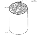
图1(a)是表示本发明的多孔结构体的一个实施方案的模式化透视图。Fig. 1(a) is a schematic perspective view showing one embodiment of the porous structure of the present invention.
图1(b)是图1(a)的Ib部分的局部放大图。Fig. 1(b) is a partially enlarged view of part Ib of Fig. 1(a).
图2(a)是表示本发明的多孔结构体的另一实施方案的模式化透视图。Fig. 2(a) is a schematic perspective view showing another embodiment of the porous structure of the present invention.
图2(b)是图2(a)的IIb部分的局部放大图。Fig. 2(b) is a partially enlarged view of part IIb of Fig. 2(a).
图3是模式化表示本发明的多孔结构体的又一实施方案的局部放大图。Fig. 3 is a partial enlarged view schematically showing still another embodiment of the porous structure of the present invention.
图4是表示本发明的多孔结构体又一实施方案的模式化透视图。Fig. 4 is a schematic perspective view showing still another embodiment of the porous structure of the present invention.
符号说明Symbol Description
1多孔结构体;2间隔壁;3孔;4多孔结构部;5外壁部;6内壳层;7外壳层;10蜂窝结构体;20泡状结构体;42、44端部。1 porous structure; 2 partition; 3 holes; 4 porous structure; 5 outer wall; 6 inner shell; 7 outer shell; 10 honeycomb structure; 20 bubble structure; 42, 44 ends.
实施发明的最佳方式The best way to practice the invention
一边参照附图一边对发明的实施方案进行详细说明,但本发明并不受这些实施方案的限定。以下,如无特别说明,截面是指与孔的通路方向(长度方向)垂直的截面。Embodiments of the invention will be described in detail with reference to the drawings, but the present invention is not limited to these embodiments. Hereinafter, unless otherwise specified, a cross section refers to a cross section perpendicular to the passage direction (longitudinal direction) of a hole.
图1(a)是本发明的多孔结构体的一个实施方案-蜂窝结构体的一个例子的模式化透视图,图1(b)是图1(a)的Ib部分的局部放大图。图1(a)、图1(b)所示方案的蜂窝结构体10(多孔结构体1)具备蜂窝结构的多孔结构部4和外壁部5。蜂窝结构的多孔结构部4具有间隔壁2,该间隔壁2形成从一个端面42贯通到另一个端面44的孔3。在多孔结构部4的外周面,形成有沿孔3的长度方向沟槽状延伸的凹部。在多孔结构部4的外周设置有外壁部5。将该外壁部5设置成一部分进入多孔结构部4的凹部内。Fig. 1(a) is a schematic perspective view of an example of a honeycomb structure, which is an embodiment of the porous structure of the present invention, and Fig. 1(b) is a partially enlarged view of part Ib of Fig. 1(a). A honeycomb structure 10 (porous structure 1 ) of an aspect shown in FIG. 1( a ) and FIG. 1( b ) includes a honeycomb-structured
该蜂窝结构体10的外壁部5是气孔率为40%以上的多孔质,优选气孔率为50%以上、进一步优选气孔率为60%以上的多孔质。通过使外壁部5为多孔质,外壁部5本身成为隔热层,多孔结构部的热量难以通过外壁传递到外部。由此,在加热多孔结构部4时,热量难以转移到外壁部5一侧,可以在短时间内使温度上升,在附载催化剂时,可以在短时间内提高催化剂活性。这样的蜂窝结构体10特别适合作为柴油发动机尾气净化用的薄壁大型蜂窝结构体使用。The
将蜂窝结构体用作捕获柴油发动机排放的烟灰的过滤器时,在其重复使用时,存在因过滤器外周部、特别是过滤器的排气口侧附近容易产生较低温而导致烟灰不能完全燃烧的问题。该问题也是热转移到外壁部的原因,通过使用上述蜂窝结构体,可以使多孔结构部的温度均匀,可以在重复使用时获得抑制碳黑残留的效果。When a honeycomb structure is used as a filter to capture soot from a diesel engine, when it is reused, the outer periphery of the filter, especially near the exhaust port side of the filter tends to generate low temperature, resulting in incomplete combustion of the soot. The problem. This problem is also a cause of heat transfer to the outer wall. By using the above-mentioned honeycomb structure, the temperature of the porous structure can be made uniform, and the effect of suppressing carbon black residue can be obtained during repeated use.
图2(a)是本发明的多孔结构体的另一实施方案-泡状结构体20(多孔结构体1)的一个例子的模式化透视图,图2(b)是图2(a)的IIb部分的局部放大图。图2(a)、图2(b)所示的泡状结构体20具备含有间隔壁2的多孔结构部4和设置于多孔结构部4外周的外壁部5,其中所述间隔壁2的配置使得可以形成互相立体连通、成为流体通路的多个孔3。孔3从一个端面42连通到另一个端面44。外壁部5为具有40%以上、优选50%以上、进一步优选60%以上的气孔率的多孔质。这样形式的多孔结构体1也可得到与上述同样的效果。以下,主要根据蜂窝结构体的实施方案,说明本发明的优选方案,但它们也适用于泡状结构体。Fig. 2 (a) is another embodiment of the porous structure of the present invention - a schematic perspective view of an example of a foam structure 20 (porous structure 1), and Fig. 2 (b) is a schematic perspective view of Fig. 2 (a) Partial enlarged view of part IIb. The
图1(a)、(b)、图2(a)、b所示的多孔结构体1中,外壁部5的气孔率如上所述,为40%以上、进一步优选50%以上,特别优选60%以上,这从提高隔热性的角度考虑是优选的,但是气孔率过高,则强度降低,不优选。因此优选气孔率为80%以下,进一步优选70%以下,特别优越60%以下。但是,如果使外壁层为多层,使内壳层形成高气孔率,使外壳层形成低气孔率以提高外壁层的强度,则优选内壳层的气孔率为80%以上。In the
作为外壁部的强度特性,优选四点弯曲强度(根据JIS 1601)为0.5MPa以上,进一步优选1.0MPa以上,特别优选2.0MPa以上。作为外壁部的微孔特性,优选通过汞压入法测定的体积基准的平均微孔径为100μm以下,进一步优选50μm以下,特别优选25μm以下。关于外壁部的微孔分布特性,通过选择作为造孔剂的中空体或其它制造条件等公知的方法,可以得到任意的微孔分布特性。优选外壁部的热膨胀系数(室温-800℃的平均值)为5.0×10⁻⁶/℃以下,进一步优选3.0×10-6/℃以下,特别优选2.0×10-6/℃以下。关于外壁部的比热,在500℃优选为5000J/kgK以下,进一步优选3000J/kgK以下,特别优选1000J/kgK以下;导热率优选5W/mK以下,进一步优选3W/mK以下,特别优选1W/mK以下。As strength characteristics of the outer wall portion, the four-point bending strength (according to JIS 1601) is preferably 0.5 MPa or more, more preferably 1.0 MPa or more, particularly preferably 2.0 MPa or more. As the pore characteristics of the outer wall portion, the volume-based average pore diameter measured by mercury intrusion porosimetry is preferably 100 μm or less, more preferably 50 μm or less, particularly preferably 25 μm or less. Regarding the pore distribution characteristics of the outer wall portion, any pore distribution characteristics can be obtained by selecting a hollow body as a pore-forming agent or other known production conditions. The thermal expansion coefficient of the outer wall portion (average value at room temperature - 800°C) is preferably 5.0×10 -6 /°C or less, more preferably 3.0×10 -6 /°C or less, particularly preferably 2.0×10 -6 /°C or less. Regarding the specific heat of the outer wall, at 500° C., it is preferably 5000 J/kgK or less, more preferably 3000 J/kgK or less, particularly preferably 1000 J/kgK or less; the thermal conductivity is preferably 5 W/mK or less, more preferably 3 W/mK or less, particularly preferably 1 W/kgK or less. Below mK.
对于多孔结构体,优选外壁部5为含有中空体的形式。中空体例如可以是二氧化硅球、飘尘球(Fly ash Balloon)、微细中空玻璃球(シラスバル一ン)、玻璃球等。通过含有所述中空体,可以得到稳定的隔热性。只要中空体的强度适度,则可提高外壁部的结构强度,有望提高蜂窝结构体对抗来自蜂窝结构体侧面的外压的强度。对于对蜂窝结构体角部的外压也有望产生抑制缺损的效果。并且,有望获得抑制涂布涂层材料并干燥时产生的干燥裂隙的效果。如果中空体具有保水性、吸水性,则抑制该干燥裂隙的效果更好。该效果可能是由于中空体使干燥时涂层内水分的急剧移动或挥发得到缓和而产生的。外壁部的气孔率可从外壁部获取测定试样,通过汞孔度计测定。中空体残留在外壁部内,汞难以渗入到中空体内,因此含有中空体时,对于外壁部的气孔率,只可测定外壁部基材部的气孔率,中空体部分的气孔率无法体现在测定值中。As for the porous structure, it is preferable that the
图3是表示另一个方案的多孔结构体的模式化局部放大图。图3所示的多孔结构体1的外壁部5含有内壳层6和外壳层7。内壳层6比外壳层7的气孔率高。通过提高位于多孔结构部4一侧的内壳层6的气孔率,可以提高隔热效果,通过降低处于比内壳层6更外周侧的外壳层7的气孔率,可以提高强度,这样,可以使外壁整体的隔热效果和强度的平衡更高。从隔热性的角度考虑,内壳层和外壳层的气孔率之差优选为5%以上,更优选为10%以上。内壳层的气孔率如果为40%以上,则外壳层的气孔率可以低于40%。从耐热冲击性的角度考虑,内壳层和外壳层的热膨胀系数差为0.8×10⁻⁶/℃以下,更优选0.4×10-6/℃以下比较好。作为提高外壳层强度的方法,优选降低外壳层的气孔率,但是降低气孔率,则层本身形成高密度,热容量增大,隔热效果将降低。因此,通过在外壳层中混入强度适中的中空体,可以在抑制外壳层整体的高密度化、高热容量化的情况下,提高强度。用于提高强度的中空体优选采用微细中空玻璃球、飘尘球等无机质、耐热性的物质。这些物质即使在蜂窝结构体制造好后,因附载催化剂而进行热处理或在实际应用时因尾气的热而暴露在高温下,仍可以保持其中空形状,保持外壳层的强度。Fig. 3 is a schematic partial enlarged view showing another embodiment of a porous structure. The
为提高外壁部整体的隔热性,优选提高内壳层的气孔率,通过在内壳层中混入中空体,可以提高气孔率,如果希望提高外壁部整体的强度,则中空体优选上述微细中空玻璃球、飘尘球等无机质、耐热性的物质。如果内壳层的强度的提高不重要,而是重视降低热容量,则优选采用发泡树脂等树脂或淀粉等有机物,它们在涂层后通过热处理可以分解、消失,可实现内壳层的低热容量化。除气孔率之外,作为外周涂层材料本身的材料特性,其结构材料的强度、耐热性、耐热冲击性、比热、导热率也成为设计因素。作为提高外壳层强度的方法,除上述混入中空体的方法之外,还可以利用:通过含浸二氧化硅溶胶并进行热处理来形成致密结构的方法;通过使用氙灯或远红外线照射对外壳层进行高温处理,形成致密结构的方法。但并不限于这些方法,也可以是公知的形成致密结构的方法、通过添加颗粒等的补强方法。In order to improve the heat insulation performance of the outer wall as a whole, it is preferable to increase the porosity of the inner shell. By mixing the hollow body in the inner shell, the porosity can be increased. If it is desired to increase the strength of the outer wall as a whole, the hollow body is preferably the fine hollow body described above. Inorganic and heat-resistant substances such as glass balls and dust balls. If it is not important to increase the strength of the inner shell, but to focus on reducing the heat capacity, it is preferable to use resins such as foamed resins or organic substances such as starch, which can be decomposed and disappeared by heat treatment after coating, and can achieve low heat capacity of the inner shell change. In addition to porosity, the strength, heat resistance, thermal shock resistance, specific heat, and thermal conductivity of the structural material, which are the material properties of the outer peripheral coating material itself, also become design factors. As a method of improving the strength of the shell layer, in addition to the above-mentioned method of mixing the hollow body, it is also possible to use: a method of forming a dense structure by impregnating silica sol and performing heat treatment; Processing, methods of forming dense structures. However, it is not limited to these methods, and a well-known method of forming a dense structure and a reinforcement method by adding particles or the like may be used.
优选使用陶瓷材料或金属材料作为多孔结构部的主要成分,也可优选使用陶瓷材料作为外壁部的主要成分。陶瓷材料有:选自堇青石、氧化铝、莫来石、硅酸铝锂、钛酸铝、二氧化钛、二氧化锆、氮化硅、氮化铝和碳化硅的至少一种,以及它们的复合物。多孔结构部还可以含有活性碳、硅胶、沸石等具有吸附功能和/或催化剂功能的材料。也可以使用金属材料作为多孔结构部的主要成分,这是由于金属材料导热性高,热量转移到外壁的多,采用本实施方案,不使热转移、而在短时间内提高孔结构部的内周孔的温度的效果显著,因此优选。外壁部除上述陶瓷材料的颗粒、例如堇青石颗粒之外,还优选含有陶瓷纤维和介于其间的非晶氧化物基质(例如由胶态二氧化硅或胶态氧化铝形成的基质)。为了使其具有更高的耐热性,还可以含有SiC颗粒等耐热性高的材料。也可以含有活性碳、硅胶、沸石等具有吸附功能和/或催化剂功能的材料。这样,可以利用将各种材料进行组合得到的胶粘材料。这里,主要成分是指构成各部的80%质量以上的材料。It is preferable to use a ceramic material or a metal material as the main component of the porous structure portion, and it is also preferable to use a ceramic material as the main component of the outer wall portion. Ceramic materials include: at least one selected from cordierite, alumina, mullite, lithium aluminum silicate, aluminum titanate, titanium dioxide, zirconium dioxide, silicon nitride, aluminum nitride and silicon carbide, and their composites things. The porous structure may also contain materials having an adsorption function and/or a catalyst function, such as activated carbon, silica gel, and zeolite. Metal material can also be used as the main component of the porous structure part. This is due to the high thermal conductivity of the metal material, and much heat is transferred to the outer wall. With this embodiment, the inner surface of the porous structure part can be improved in a short time without heat transfer. The effect of the temperature of the peripheral hole is remarkable, so it is preferable. The outer wall portion preferably contains ceramic fibers with an intervening amorphous oxide matrix (eg, a matrix formed of colloidal silica or colloidal alumina) in addition to particles of the above-mentioned ceramic material, such as cordierite particles. In order to have higher heat resistance, materials with high heat resistance such as SiC particles may be contained. It may also contain activated carbon, silica gel, zeolite and other materials with adsorption function and/or catalyst function. In this way, an adhesive material obtained by combining various materials can be used. Here, the main component refers to a material constituting 80% by mass or more of each part.
本发明的多孔结构体中,优选在孔内(间隔壁表面)和/或间隔壁内部的微孔内表面附载催化剂。这适合用于吸附或吸收汽车尾气等由内燃机排放的排气中含有的HC、NOx、CO等气体成分和/或以碳为核的固体成分或者SOF等微粒状物质,净化排气。如上所述应用本发明的多孔结构体时,为了使催化剂尽早活化,升温速度特别重要,本发明的多孔结构体更为有利。优选的催化剂有:Pt、Pd、Rh等贵金属类、碱金属类、碱土金属类、稀土类等。优选将它们的一种以上附载于孔内和/或上述间隔壁内部。例如将具有高比表面积的γ氧化铝以数μm至数十μm的厚度薄薄涂布于上述孔内和/或上述间隔壁内部,形成涂层,在该氧化铝内的微孔表面分散附载上述催化剂、例如Pt颗粒和Pd颗粒,这样可以高效地对通过孔内和/或孔间隔壁内部的排气中的HC等进行氧化处理。In the porous structure of the present invention, it is preferable to carry the catalyst on the inside of the pores (the surface of the partition wall) and/or the inner surface of the micropores inside the partition wall. This is suitable for adsorbing or absorbing gas components such as HC, NOx, and CO contained in exhaust gas emitted from internal combustion engines such as automobile exhaust, and/or solid components with carbon as a nucleus or particulate matter such as SOF to purify exhaust gas. When the porous structure of the present invention is used as described above, the rate of temperature increase is particularly important in order to activate the catalyst early, and the porous structure of the present invention is more advantageous. Preferable catalysts include noble metals such as Pt, Pd, and Rh, alkali metals, alkaline earth metals, and rare earths. It is preferable to carry one or more of these in the pores and/or inside the above-mentioned partition walls. For example, γ-alumina with a high specific surface area is thinly coated in the above-mentioned pores and/or inside the above-mentioned partition wall with a thickness of several μm to tens of μm to form a coating, and the surface of the micropores in the alumina is dispersed and loaded. The above-mentioned catalysts, such as Pt particles and Pd particles, can efficiently oxidize HC and the like in the exhaust gas passing through the pores and/or the interior of the pore partition walls.
本发明的多孔结构体、特别是蜂窝结构体中,其孔的至少一部分在端部封闭,这是作为过滤器使用的优选方案。如图4所示,两端部42、44的孔交替封闭呈格子状,通过形成这样的结构,使全部流体通过孔的间隔壁,这样的蜂窝结构体适合作为过滤器使用。用作过滤器时,多孔结构部的间隔壁必须是多孔质材料,可优选使用上述陶瓷材料。特别是在捕获由柴油发动机排放的烟灰的过滤器中,例如使用蜂窝结构体,则可以通过燃烧除去捕获的烟灰,可使蜂窝结构体重复使用。在该重复使用中,为了应对上述烟灰未完全燃尽的问题,优选在上述过滤器中使用本发明的一个实施方案的蜂窝结构体。The porous structure of the present invention, especially the honeycomb structure, is preferably used as a filter in which at least a part of the pores are closed at the ends. As shown in FIG. 4 , the pores at both ends 42 and 44 are closed alternately in a lattice shape. By forming such a structure, all the fluid passes through the partition walls of the pores. Such a honeycomb structure is suitable for use as a filter. When used as a filter, the partition wall of the porous structure must be made of a porous material, and the above-mentioned ceramic materials can be preferably used. In particular, in a filter for trapping soot emitted from a diesel engine, for example, a honeycomb structure is used, and the trapped soot can be removed by burning, so that the honeycomb structure can be reused. In this repeated use, it is preferable to use the honeycomb structure of one embodiment of the present invention for the above-mentioned filter in order to cope with the above-mentioned problem of incomplete combustion of soot.
本发明的多孔结构体的截面形状没有特别限制,除圆形外,可以是椭圆形或长圆形、异形。多孔结构体的截面积也有没特别限制,如上所述,更优选适用大型的多孔结构体,因此优选具有相当于直径100mm以上、特别是130mm以上的圆形的截面积的多孔结构体。孔的截面形状可以是三角形、四角形、六角形、圆形等任何形状,没有特别限定。间隔壁的厚度没有特别限制,例如可以是30-2000μm、优选40-1000μm、进一步优选50-500μm的范围。特别是本发明优选适用间隔壁薄的多孔结构体,因此间隔壁厚度为130μm以下、特别是80μm以下的多孔结构体是特别优选的方案。间隔壁优选为多孔质,例如优选制成30-90%体积的气孔率。孔密度(单位截面积的孔数)没有特别限定,例如可以是6-2000孔/平方英寸(0.9-311孔/cm2)、优选50-1000孔/平方英寸(7.8-155孔/cm2)、进一步优选100-400孔/平方英寸(15.5-62.0孔/cm2)的范围。The cross-sectional shape of the porous structure of the present invention is not particularly limited, and may be elliptical, oblong, or irregular in addition to circular. The cross-sectional area of the porous structure is not particularly limited, but as described above, it is more preferable to apply a large porous structure, so a porous structure having a cross-sectional area equivalent to a circle with a diameter of 100 mm or more, especially 130 mm or more is preferable. The cross-sectional shape of the hole may be any shape such as a triangle, a square, a hexagon, or a circle, and is not particularly limited. The thickness of the partition wall is not particularly limited, for example, it may be in the range of 30-2000 μm, preferably 40-1000 μm, more preferably 50-500 μm. In particular, the present invention is preferably applied to a porous structure with a thin partition wall, and therefore a porous structure with a partition wall thickness of 130 μm or less, especially 80 μm or less is particularly preferable. The partition wall is preferably porous, for example, preferably has a porosity of 30 to 90% by volume. The pore density (the number of pores per unit cross-sectional area) is not particularly limited, for example, it can be 6-2000 pores/square inch (0.9-311 pores/cm 2 ), preferably 50-1000 pores/square inch (7.8-155 pores/cm 2 ), more preferably in the range of 100-400 pores/square inch (15.5-62.0 pores/cm 2 ).
下面,根据具体例子说明本发明的多孔结构体的制造方法。该具体例子中,首先将成型原料制成坯土。即,向适合上述多孔结构部的主要成分或形成优选的主要成分的原料中添加粘合剂、例如甲基纤维素和羟基丙氧基甲基纤维素,再添加表面活性剂和水,将其混炼制成坯土,其中所述原料例如是通过煅烧形成堇青石的堇青石化原料或形成碳化硅-金属硅复合物的碳化硅粉和金属硅粉。这里,堇青石化原料例如是将滑石粉、高岭土、预烧高龄土、氧化铝、氢氧化铝、二氧化硅等按照规定的比例混合,使化学组成在以下范围的物质:SiO2为42-56%质量、Al2O3为30-45%质量,MgO为12-16%质量。Next, the method for producing the porous structure of the present invention will be described based on specific examples. In this specific example, the molding raw material is first made into clay. That is, a binder such as methyl cellulose and hydroxypropoxymethyl cellulose is added to a main component suitable for the above-mentioned porous structure or a raw material forming a preferable main component, and a surfactant and water are added to make it Kneading is made into kneaded clay, wherein the raw material is, for example, a cordierite raw material that is calcined to form cordierite, or silicon carbide powder and metal silicon powder that form a silicon carbide-metal silicon composite. Here, the cordierite-forming raw material is, for example, a substance in which talc powder, kaolin, calcined kaolin, alumina, aluminum hydroxide, silica, etc. are mixed in a prescribed ratio so that the chemical composition falls within the following range: SiO 2 is 42- 56% by mass, Al 2 O 3 by 30-45% by mass, and MgO by 12-16% by mass.
接着,通过将该坯土成型,得到具有间隔壁的成型体,该间隔壁形成多个孔。成型的方法没有特别限制,通常优选挤出成型,优选使用活塞式挤出机或双螺杆连续挤出机等。使用双螺杆连续挤出机,可以连续进行形成坯土步骤和成型步骤。此时,可以成型为不含外周壁的成型体,但从抑制间隔壁变形的角度考虑,优选成型为含有与间隔壁一体化的外周壁的成型体。Next, by molding this clay, a molded body having partition walls forming a plurality of holes is obtained. The molding method is not particularly limited, and extrusion molding is usually preferred, preferably using a piston extruder or a twin-screw continuous extruder. Using a twin-screw continuous extruder, the clay forming step and the molding step can be performed continuously. In this case, the molded body may be molded without the outer peripheral wall, but it is preferably molded into a molded body including the outer peripheral wall integrated with the partition wall from the viewpoint of suppressing deformation of the partition wall.
接着,将所得成型体用例如微波、介电、和/或热风等干燥,然后将干燥的成型体进行煅烧,得到煅烧体。此时的煅烧温度和气体气氛可根据所使用的原料适当改变,本领域技术人员均可以选择适合所用原料的最佳煅烧温度和气体气氛。例如,使用堇青石化原料时,在大气中加热脱脂,然后在大气中以最高温度1400-1450℃左右的温度进行煅烧;以碳化硅粉和金属硅粉作为原料时,可在大气或N2气氛中加热脱脂,然后在Ar气氛中以1550℃左右进行煅烧。煅烧时,通常使用单炉或隧道炉等连续炉,由此,可同时或连续进行脱脂·煅烧。Next, the obtained molded body is dried by using, for example, microwave, dielectric, and/or hot air, and then the dried molded body is calcined to obtain a calcined body. The calcination temperature and gas atmosphere at this time can be appropriately changed according to the raw materials used, and those skilled in the art can select the optimum calcination temperature and gas atmosphere suitable for the raw materials used. For example, when using cordierite as a raw material, heat and degrease in the atmosphere, and then calcine in the atmosphere at a maximum temperature of about 1400-1450°C; when using silicon carbide powder and metal silicon powder as raw materials, the It is degreased by heating in the atmosphere, and then calcined at about 1550°C in the Ar atmosphere. For calcination, a continuous furnace such as a single furnace or a tunnel furnace is generally used, whereby degreasing and calcination can be performed simultaneously or continuously.
接着,根据需要,加工除去煅烧体的外周的至少一部分,优选外周整体。该步骤不是必须的,但是外周附近的间隔壁在之前这些步骤中可能发生变形,因此优选除去外周附近的间隔壁。在获得成型体的步骤中,如果要获得含有与间隔壁一体化的外周壁的成型体,也需要除去该外周壁。此时优选与外周壁附近的间隔壁一起除去外周壁。除去外周的至少一部分的步骤可以对煅烧前的成型体进行。对成型体或煅烧体的外周进行加工除去,优选使所除去外周的范围例如为除去从外周开始2个孔以上的部分,进一步优选除去从外周开始2-4个孔的部分。除去孔时,通过在成型体或煅烧体的外周面除去形成孔的间隔壁的一部分,使该孔向外周面开口形成凹部,在设置后述的涂敷材料的步骤中,可以将涂敷材料设置到陷入凹部内,这样可提高外壁的强度。在获得成型体的步骤中,有时通过制造没有外周壁形状的成型体,可以无需进行除去外周的步骤,优选获得不含外周壁的成型体,从而无需加工除去外周部,即可进行后述形成外壁部的步骤。Next, if necessary, at least a part of the outer periphery of the calcined body is processed and removed, preferably the entire outer periphery. This step is not essential, but the partition wall near the outer periphery may be deformed in these previous steps, so it is preferable to remove the partition wall near the outer periphery. In the step of obtaining a molded article, if a molded article including an outer peripheral wall integrated with a partition wall is to be obtained, it is also necessary to remove the outer peripheral wall. At this time, it is preferable to remove the outer peripheral wall together with the partition walls in the vicinity of the outer peripheral wall. The step of removing at least a part of the periphery can be performed on the molded body before firing. The outer periphery of the molded body or calcined body is processed and removed. The removed outer periphery is preferably removed from the outer periphery, for example, 2 or more holes, more preferably 2-4 holes from the outer periphery. When removing the hole, by removing a part of the partition wall forming the hole on the outer peripheral surface of the compact or calcined body, the hole is opened to the outer peripheral surface to form a recess, and the coating material can be applied in the step of setting the coating material described later. Set into the recessed part, which can improve the strength of the outer wall. In the step of obtaining a molded body, sometimes by producing a molded body without the shape of the outer peripheral wall, the step of removing the outer periphery can be eliminated. It is preferable to obtain a molded body without the outer peripheral wall, so that the formation described later can be performed without processing and removing the outer peripheral portion. Steps on the outer wall.
接着在煅烧体的外周设置含有造孔剂的涂敷材料,形成外壁部。通过使涂敷材料中含有造孔剂,可以容易地形成气孔率高的外壁部。造孔剂只要是可在外壁部形成气孔的物质即可,没有特别限制,例如有:碳;二氧化硅球、飘尘球、微细中空玻璃球、玻璃球等球类;未发泡或已发泡的发泡树脂;聚对苯二甲酸乙二醇脂的均聚物或共聚物等聚酯树脂;聚甲基丙烯酸甲酯的均聚物或共聚物等丙烯酸树脂;淀粉等。其中,从可有效地形成规定形状的气孔的角度考虑,优选中空体-球类和已发泡的发泡树脂,优选即使加热也不消失的无机中空体。Next, a coating material containing a pore-forming agent is provided on the outer periphery of the calcined body to form an outer wall portion. By including a pore-forming agent in the coating material, an outer wall portion with a high porosity can be easily formed. The pore forming agent is not particularly limited as long as it is a substance that can form pores on the outer wall, for example: carbon; balls such as silica balls, floating dust balls, fine hollow glass balls, glass balls; unfoamed or expanded foaming resin; polyester resin such as homopolymer or copolymer of polyethylene terephthalate; acrylic resin such as homopolymer or copolymer of polymethyl methacrylate; starch, etc. Among them, from the viewpoint of effectively forming pores of a predetermined shape, hollow bodies-balls and foamed resins are preferable, and inorganic hollow bodies that do not disappear even when heated are preferable.
造孔剂的量没有特别限制,优选外壁部的气孔率达到30%以上、进一步优选达到40%以上、特别优选达到50%以上的量。优选气孔率达到80%以下、进一步优选达到70%以下、特别优选达到60%以下的量。具体来说,相对于100质量份除了造孔剂之外的涂敷材料,造孔剂的量为3质量份以上,进一步优选5质量份以上,特别优选15质量份以上,优选30质量份以下,进一步优选25质量份以下,特别优选20质量份以下。The amount of the pore forming agent is not particularly limited, but it is preferably an amount in which the porosity of the outer wall portion reaches 30% or more, more preferably 40% or more, particularly preferably 50% or more. The porosity is preferably 80% or less, more preferably 70% or less, particularly preferably 60% or less. Specifically, with respect to 100 parts by mass of the coating material other than the pore-forming agent, the amount of the pore-forming agent is 3 parts by mass or more, more preferably 5 parts by mass or more, particularly preferably 15 parts by mass or more, and preferably 30 parts by mass or less , more preferably 25 parts by mass or less, particularly preferably 20 parts by mass or less.
涂敷材料除含有上述造孔剂之外,优选含有选自适合上述外壁的主要成分的陶瓷材料中的至少一种材料,进一步优选含有与孔结构部的主要成分相同种类的陶瓷颗粒。这些陶瓷颗粒的具体例子有:堇青石、氧化铝、莫来石、硅酸铝锂、钛酸铝、二氧化钛、二氧化锆、氮化硅、氮化铝和碳化硅等。涂敷材料除陶瓷颗粒之外,还优选含有胶体二氧化硅和/或胶体氧化铝,进一步优选含有陶瓷纤维,更进一步优选含有无机粘合剂,又进一步优选含有有机粘合剂。优选向这些原料中加入水等液体成分,制成浆状,将其作为涂敷材料配置。The coating material preferably contains at least one material selected from ceramic materials suitable for the main component of the outer wall in addition to the above-mentioned pore-forming agent, and more preferably contains the same type of ceramic particles as the main component of the pore structure. Specific examples of these ceramic particles include cordierite, alumina, mullite, lithium aluminum silicate, aluminum titanate, titanium dioxide, zirconium dioxide, silicon nitride, aluminum nitride, silicon carbide, and the like. In addition to ceramic particles, the coating material preferably contains colloidal silica and/or colloidal alumina, more preferably contains ceramic fibers, still more preferably contains an inorganic binder, still more preferably contains an organic binder. It is preferable to add a liquid component, such as water, to these raw materials, make a slurry, and arrange|position it as a coating material.
在对煅烧体设置涂敷材料的情况下,在设置涂敷材料后进行加热干燥,这可以使液体成分尽早蒸发,形成外周壁,因此优选。例如在80℃以上的温度下进行干燥,可以提高外周壁的强度。设置涂敷材料的方法没有特别限制,除以往进行的涂布等之外,还可以使用火焰喷涂等方法。When the coating material is provided on the calcined body, it is preferable to heat and dry the calcined body after the coating material is provided because the liquid component can be evaporated as early as possible and the outer peripheral wall can be formed. For example, drying at a temperature of 80° C. or higher can increase the strength of the peripheral wall. The method of placing the coating material is not particularly limited, and methods such as flame spraying may be used in addition to conventional coating and the like.
为了使外壁部含有内壳层和外壳层,可以将造孔剂含量多的涂敷材料设置在孔结构部的外周,在其外侧设置造孔剂含量少的涂敷材料。In order to make the outer wall part contain an inner shell layer and an outer shell layer, a coating material with a high pore-forming agent content can be provided on the outer periphery of the pore structure part, and a coating material with a low pore-forming agent content can be provided outside it.
这样形成的多孔结构体与通常的多孔结构体,即,通过将间隔壁和外周壁一体化挤出成型并干燥、成型而形成的间隔壁与外周壁成为一体的多孔结构体不同。对于本发明的多孔结构体而言,在煅烧体的外周面设置涂敷材料后不进行煅烧的情况下,多孔结构部和外壁部的交界处可能存在物理性界面。在外周面设置涂敷材料后进行煅烧的情况下,如果两者材料不同,则两者之间也可能存在界面。即使材料相同,如果两者为堇青石,通过挤出形成的多孔结构部和通过设置形成的外壁部在取向上不同,两者之间也存在界面。即使两者为堇青石以外的相同材料,通常由于一些组成上的不同或形成过程的不同,导致微孔形态或结晶颗粒形态等不同,由此形成组织性界面,或者由于元素分布的不同等而导致可能存在化学性界面。另一方面,通常的多孔结构体由相同材料通过相同的形成过程形成,因此不存在所述界面。因此,通常的多孔结构体难以严格区分外壁部和多孔结构部,但是通过上述制造方法形成的多孔结构体可以区分外壁部和多孔结构部。The porous structure formed in this way is different from a general porous structure, that is, a porous structure in which the partition wall and the peripheral wall are integrally formed by extrusion molding the partition wall and the peripheral wall, drying and molding. In the porous structure of the present invention, when the calcined body is not fired after the coating material is provided on the outer peripheral surface, a physical interface may exist at the boundary between the porous structure portion and the outer wall portion. When firing is performed after providing a coating material on the outer peripheral surface, if the two materials are different, there may be an interface between the two. Even if the materials are the same, if both are cordierite, the porous structure part formed by extrusion and the outer wall part formed by setting are different in orientation, and an interface exists between the two. Even if the two are the same material other than cordierite, usually due to some compositional differences or differences in the formation process, resulting in differences in microporous morphology or crystal particle morphology, thereby forming a structured interface, or due to differences in element distribution, etc. lead to the possible existence of a chemical interface. On the other hand, a general porous structure is formed from the same material through the same formation process, so the interface does not exist. Therefore, it is difficult to strictly distinguish the outer wall part from the porous structure part in a general porous structure, but the porous structure formed by the above-mentioned production method can distinguish the outer wall part from the porous structure part.
本发明的多孔结构体的制造方法中,优选包含将多个成型体或煅烧体、优选煅烧体进行接合的步骤。通过包含该步骤,所形成的多孔结构体形成片段化的多个孔状结构片段互相接合的结构,耐热冲击性提高。在接合步骤中使用的接合材料没有特别限制,例如可以使用与涂敷材料相同的材料。优选该步骤在形成外壁的步骤之前进行,当制造方法中包含任意的除去外周的步骤时,优选在该步骤之前进行。即,优选通过接合步骤将多个成型体或煅烧体进行接合,制成规定的大小,然后除去其外周,制成所需形状的多孔结构部。In the method for producing a porous structure of the present invention, it is preferable to include a step of joining a plurality of molded bodies or calcined bodies, preferably calcined bodies. By including this step, the formed porous structure has a structure in which a plurality of fragmented porous structure segments are joined to each other, and thermal shock resistance is improved. The bonding material used in the bonding step is not particularly limited, and for example, the same material as the coating material can be used. This step is preferably performed before the step of forming the outer wall, and when any step of removing the outer periphery is included in the production method, it is preferably performed before this step. That is, it is preferable to join a plurality of molded bodies or calcined bodies into a predetermined size in a joining step, and then remove the outer periphery thereof to form a porous structure part of a desired shape.
将多孔结构体、特别是蜂窝结构体用于过滤器、特别是DPF等中时,要将部分孔的开口部的端面通过封闭材料封闭,这是用作过滤器时优选的方案。如图4所示,优选在两端部42、44,使孔交互封闭,使两端部呈格子图案。封闭可如下进行:遮掩不需封闭的孔,将封闭材料制成浆状,设置于片段开口端面,干燥后进行煅烧。封闭如果在成型步骤之后、煅烧步骤之前进行,则煅烧步骤一次即可完成,因而优选,但也可以在煅烧后进行封闭,只要是成型后即可,可在任何时期进行。封闭材料没有特别限制,可以使用与成型原料相同的材料。另外,在多孔结构体上附载催化剂时,用含有上述优选的催化剂的溶液或浆涂底漆,然后加热,这样即可在孔内和/或上述间隔壁内部附载催化剂。When using a porous structure, especially a honeycomb structure, in a filter, especially a DPF, it is preferable to seal the end faces of the openings of some pores with a sealing material. As shown in FIG. 4 , it is preferable to alternately close the holes at both ends 42 and 44 so that the two ends form a lattice pattern. The sealing can be carried out as follows: cover the holes that do not need to be sealed, make the sealing material into a slurry, arrange it on the end face of the opening of the segment, and then calcining after drying. If the sealing is performed after the molding step and before the calcination step, it is preferable to complete the calcination step once, but the sealing can also be performed after the calcination, and it can be performed at any time as long as it is after the molding. The sealing material is not particularly limited, and the same material as the molding material can be used. In addition, when the catalyst is supported on the porous structure, a primer is applied with a solution or slurry containing the above-mentioned preferred catalyst, followed by heating, so that the catalyst can be supported in the pores and/or inside the partition wall.
实施例Example
以下,根据实施例进一步详细说明本发明,本发明不受这些实施例的限定。Hereinafter, the present invention will be described in further detail based on examples, but the present invention is not limited by these examples.
(多孔结构部的制作)(Preparation of porous structure part)
向堇青石化原料、即微粒滑石粉、高岭土、氧化铝和其它堇青石化原料中加入成型助剂、造孔剂和水,进行调制,然后混合混炼,使用该混炼物(坯土)进行挤押成型,制造蜂窝状的成型体。接着,向成型体规定的孔的开口部导入封闭材料,干燥,然后煅烧蜂窝状的成型体,得到规定开口部封闭的蜂窝状的煅烧体。然后,通过研磨加工除去煅烧体的外周,使外径尺寸比规定尺寸小,形成多个孔,得到在外周面沿孔的通路方向形成沟槽状延伸的凹部、并含有间隔壁的蜂窝状多孔结构部(孔状结构:间隔壁厚度0.42mm、孔间距2.5mm)。A cordierite-forming raw material, ie, fine-grained talc, kaolin, alumina, and other cordierite-forming raw materials, is prepared by adding a molding aid, a pore-forming agent, and water, and then mixed and kneaded, and the kneaded product (kneaded clay) is used Extrusion molding is performed to produce a honeycomb-shaped molded body. Next, a sealing material is introduced into the openings of the predetermined pores of the molded body, dried, and then the honeycomb molded body is fired to obtain a honeycomb fired body with the predetermined openings closed. Then, remove the outer periphery of the calcined body by grinding, make the outer diameter smaller than the specified size, form a plurality of pores, and obtain a honeycomb-like porous structure with groove-like extending recesses formed on the outer peripheral surface along the passage direction of the holes and containing partition walls. Structure part (porous structure: partition wall thickness 0.42 mm, hole pitch 2.5 mm).
(外壁部的形成)(Formation of outer wall part)
调制表1所示的调制比例(质量份)的涂敷材料,将涂敷材料涂布于多孔结构部的外周面,干燥,然后在400℃进行预烧,得到实施例1-6和比较例1的蜂窝结构体(直径267mm×长度178mm、外壁部厚度1.2mm)。按照表2所示调制比例(质量份),制备形成内壳层的内涂敷材料和形成外壳层的外涂敷材料,将内涂敷材料涂布于与上述同样的多孔结构部的外周面,干燥,然后从其上涂布外涂敷材料,干燥,然后在400℃进行预烧,得到实施例7和8的蜂窝结构体(直径267mm×长度178mm、内壳层的厚度0.7mm、外壳层的厚度0.7mm)。Prepare the coating material with the preparation ratio (parts by mass) shown in Table 1, apply the coating material on the outer peripheral surface of the porous structure part, dry it, and then pre-fire it at 400°C to obtain Examples 1-6 and Comparative Example 1 honeycomb structure (diameter 267 mm x length 178 mm, outer wall thickness 1.2 mm). According to the preparation ratio (parts by mass) shown in Table 2, the inner coating material forming the inner shell layer and the outer coating material forming the outer shell layer were prepared, and the inner coating material was applied to the outer peripheral surface of the same porous structure as above. , dried, and then coated with an outer coating material thereon, dried, and then calcined at 400° C. to obtain the honeycomb structures of Examples 7 and 8 (diameter 267 mm × length 178 mm, inner shell thickness 0.7 mm, outer shell Layer thickness 0.7 mm).

[表2][Table 2]

造孔剂①:发泡树脂(松本油脂株式会社/F-50E)、平均粒径约40μmPore-forming agent ①: Foaming resin (Matsumoto Yushi Co., Ltd./F-50E), average particle size about 40 μm
造孔剂②:飘尘球、平均粒径约40μmPore-forming agent ②: floating dust balls, with an average particle size of about 40 μm
(外壁部的气孔率测定)(Measurement of Porosity of Outer Wall)
从所得蜂窝结构体切下外壁部,测定气孔率。以下表示气孔率的测定方法。在测定气孔率的同时,也可以求出微孔径分布,将体积基准的平均微孔径用作微孔径的代表值。The outer wall portion was cut out from the obtained honeycomb structure, and the porosity was measured. The measuring method of the porosity is shown below. Simultaneously with the measurement of the porosity, the pore diameter distribution may be obtained, and the volume-based average pore diameter may be used as a representative value of the pore diameter.
(1)将测定试样在150℃干燥两小时,然后装入容器,设置在装置上。在添加发泡树脂作为造孔剂的情况下,在550℃热处理1小时后进行设置。(1) After drying the measurement sample at 150° C. for two hours, it is placed in a container and installed on the device. In the case of adding a foaming resin as a pore-forming agent, it is installed after heat-treating at 550° C. for 1 hour.
(2)向容器内注入汞,施加对应于规定微孔径的压力,求出被测定试样吸收的汞容积。(2) Mercury is injected into the container, a pressure corresponding to a predetermined pore diameter is applied, and the volume of mercury absorbed by the measurement sample is obtained.
(3)微孔分布由压力和所吸收的汞容积计算求出。(3) The pore distribution is calculated from the pressure and the volume of mercury absorbed.
(4)微孔容积由施加68.6MPa(700kgf/cm2)的压力所吸收的汞容积计算求出。(4) The pore volume was calculated from the volume of mercury absorbed under a pressure of 68.6 MPa (700 kgf/cm 2 ).
(5)气孔率按照下式,由总微孔容积求出。(5) The porosity was obtained from the total pore volume according to the following formula.
气孔率(%)=总微孔容积(每1g)×100/(总微孔容积(每1g)+1/2.52)Porosity (%) = total micropore volume (per 1g) × 100/(total micropore volume (per 1g) + 1/2.52)
(外壁部升温速度的测定)(Measurement of temperature rise rate of outer wall part)
将所得蜂窝结构体设置于燃烧实验装置上,向陶瓷蜂窝结构体的多孔结构部通入约400℃的燃烧气体。此时,测定外壁部的温度,评定持续上升的温度停止上升、外壁部的温度达到恒定状态为止的时间。将评价后的陶瓷蜂窝结构体取出,评价外周涂敷部有否缺损。The obtained honeycomb structure was installed on a combustion test apparatus, and a combustion gas at about 400° C. was passed through the porous structure portion of the ceramic honeycomb structure. At this time, the temperature of the outer wall was measured, and the time until the temperature of the outer wall stopped rising and the temperature of the outer wall reached a constant state was evaluated. The evaluated ceramic honeycomb structure was taken out, and the presence or absence of chipping in the outer peripheral coated portion was evaluated.
表3表示外壁部的气孔率、燃烧实验中外壁部温度达到恒定的时间以及有否缺损的评价结果。对于外壁部的气孔率、燃烧实验时外壁部温度达到恒定的时间以及有否缺损,按照各n=2进行评价。Table 3 shows the porosity of the outer wall, the time taken for the temperature of the outer wall to become constant in the combustion test, and the evaluation results of the presence or absence of cracks. The porosity of the outer wall, the time taken for the temperature of the outer wall to become constant during the combustion test, and the presence or absence of defects were evaluated so that each n=2.
[表3][table 3]

如表3所示,与比较例1相比较,使用添加有造孔剂的涂敷材料的实施例1-6,其气孔率增高,同时燃烧实验中,外壁部温度达到恒定的时间延长。即,实施例1-6的蜂窝结构体隔热效果高,例如作为排气催化剂载体使用时,热量转移到外壁部的少,多孔结构部的温度容易上升。实施例5和6中,显示了高的气孔率和隔热效果,但观察到外壁部有缺损。这是由于气孔率高,外壁部的强度降低。不过,即使是上述气孔率,通过使用强度更高的原材料成分等,也可以弥补强度降低的缺陷,因此认为在可实用的范围内。As shown in Table 3, compared with Comparative Example 1, the porosity of Examples 1-6 using the coating material added with a pore-forming agent was increased, and the time for the outer wall temperature to reach a constant temperature in the combustion test was prolonged. That is, the honeycomb structure of Examples 1-6 has a high thermal insulation effect, and when used as an exhaust catalyst carrier, for example, less heat is transferred to the outer wall, and the temperature of the porous structure is likely to rise. In Examples 5 and 6, high porosity and thermal insulation effect were exhibited, but defects were observed in the outer wall. This is because the strength of the outer wall portion decreases due to the high porosity. However, even with the above-mentioned porosity, it is considered that it is within a practical range because it can make up for the defect of strength reduction by using a higher-strength raw material component or the like.
将外壁部制成外壳层和内壳层两层的实施例7和8中,通过使内壳层具有高气孔率,可得到隔热效果,通过使外壳层具有较低的气孔率,可以实现更高的强度。In Examples 7 and 8 in which the outer wall is made into two layers, the outer shell and the inner shell, the heat insulation effect can be obtained by making the inner shell have a high porosity, and the heat insulation effect can be achieved by making the outer shell have a lower porosity. higher strength.
产业实用性Industrial applicability
如以上说明,本发明的多孔结构体外壁部的隔热性高,因此可以使多孔结构部的升温速度提高,使多孔结构部的温度分布更均匀。因此,可广泛用作排气净化用的催化剂载体、过滤器等。本发明的蜂窝结构体的制造方法可适合用于制造上述蜂窝结构体。As explained above, since the outer wall of the porous structure of the present invention has high heat insulation performance, the rate of temperature increase of the porous structure can be increased and the temperature distribution of the porous structure can be made more uniform. Therefore, it can be widely used as a catalyst carrier, a filter, and the like for purifying exhaust gas. The method for producing a honeycomb structure of the present invention can be suitably used for producing the above-mentioned honeycomb structure.
Claims (17)
Applications Claiming Priority (2)
| Application Number | Priority Date | Filing Date | Title |
|---|---|---|---|
| JP2004008263A JP4550434B2 (en) | 2004-01-15 | 2004-01-15 | Cell structure and manufacturing method thereof |
| JP008263/2004 | 2004-01-15 |
Publications (2)
| Publication Number | Publication Date |
|---|---|
| CN1933889A CN1933889A (en) | 2007-03-21 |
| CN100431663C true CN100431663C (en) | 2008-11-12 |
Family
ID=34792218
Family Applications (1)
| Application Number | Title | Priority Date | Filing Date |
|---|---|---|---|
| CNB2005800079099A Expired - Lifetime CN100431663C (en) | 2004-01-15 | 2005-01-13 | Porous structure and its manufacturing method |
Country Status (5)
| Country | Link |
|---|---|
| US (1) | US7615273B2 (en) |
| EP (1) | EP1704908B1 (en) |
| JP (1) | JP4550434B2 (en) |
| CN (1) | CN100431663C (en) |
| WO (1) | WO2005068048A1 (en) |
Cited By (1)
| Publication number | Priority date | Publication date | Assignee | Title |
|---|---|---|---|---|
| CN107774325A (en) * | 2016-08-26 | 2018-03-09 | 恩亿凯嘉股份有限公司 | Honeycomb structured body, honeycomb structure type catalyst and manufacture method |
Families Citing this family (35)
| Publication number | Priority date | Publication date | Assignee | Title |
|---|---|---|---|---|
| FR2889184B1 (en) * | 2005-07-29 | 2007-10-19 | Saint Gobain Ct Recherches | PROCESS FOR THE PREPARATION OF A POROUS STRUCTURE USING POROGENIC SILICA AGENTS |
| WO2007086183A1 (en) | 2006-01-27 | 2007-08-02 | Ibiden Co., Ltd. | Honeycomb structure and process for producing the same |
| EP1813339B1 (en) * | 2006-01-27 | 2013-03-06 | Ibiden Co., Ltd. | Honeycomb structure and method for manufacturing honeycomb structure |
| JP4975331B2 (en) * | 2006-02-02 | 2012-07-11 | 日本碍子株式会社 | Method for manufacturing plugged honeycomb structure and plugged honeycomb structure |
| JP4900663B2 (en) * | 2006-03-08 | 2012-03-21 | 独立行政法人産業技術総合研究所 | Exhaust gas purification filter and manufacturing method thereof |
| EP2008987B1 (en) * | 2006-03-30 | 2018-06-27 | NGK Insulators, Ltd. | Honeycomb structure body |
| EP2024299A2 (en) * | 2006-05-31 | 2009-02-18 | Corning Incorporated | Crack-resistant ceramic honeycomb articles and methods of manufacturing same |
| FR2902423B1 (en) * | 2006-06-19 | 2008-09-12 | Saint Gobain Ct Recherches | JOINT CEMENT FOR PARTICLE FILTER. |
| EP2039428B1 (en) | 2006-06-23 | 2014-05-14 | NGK Insulators, Ltd. | Honeycomb structure and method for manufacturing same |
| JP2008043851A (en) * | 2006-08-11 | 2008-02-28 | Tokyo Yogyo Co Ltd | Honeycomb structure |
| JP2008136981A (en) * | 2006-12-05 | 2008-06-19 | Tokyo Yogyo Co Ltd | Honeycomb structure |
| WO2008120390A1 (en) * | 2007-03-29 | 2008-10-09 | Ibiden Co., Ltd. | Process for producing honeycomb structure and honeycomb structure |
| EP1982966B1 (en) | 2007-03-29 | 2011-11-09 | Ibiden Co., Ltd. | Honeycomb structure and method of producing honeycomb structure |
| JPWO2008126305A1 (en) * | 2007-03-30 | 2010-07-22 | イビデン株式会社 | Catalyst carrier and exhaust gas treatment device |
| JP4571989B2 (en) * | 2008-02-28 | 2010-10-27 | 日本碍子株式会社 | Manufacturing method of ceramic honeycomb structure and coating material used therefor |
| JP5266865B2 (en) | 2008-05-13 | 2013-08-21 | いすゞ自動車株式会社 | Exhaust gas purification system and control method thereof |
| JP4402732B1 (en) * | 2008-07-16 | 2010-01-20 | 東京窯業株式会社 | Honeycomb structure |
| JP5292013B2 (en) * | 2008-08-07 | 2013-09-18 | 日本碍子株式会社 | Honeycomb structure |
| JP2010131589A (en) | 2008-10-31 | 2010-06-17 | Ngk Insulators Ltd | Honeycomb structure, and reactor using honeycomb structure |
| US8263512B2 (en) | 2008-12-15 | 2012-09-11 | Unifrax I Llc | Ceramic honeycomb structure skin coating |
| US20100304041A1 (en) * | 2009-05-29 | 2010-12-02 | Tonia Havewala Fletcher | Method For Coating Honeycomb Bodies |
| CN103889929B (en) * | 2011-10-11 | 2015-11-25 | 日立金属株式会社 | Manufacturing method of ceramic honeycomb structure and ceramic honeycomb structure |
| WO2013136848A1 (en) | 2012-03-14 | 2013-09-19 | 日本碍子株式会社 | Sealed honeycomb structure |
| WO2013141244A1 (en) * | 2012-03-19 | 2013-09-26 | 京セラ株式会社 | Honeycomb structure body and gas-processing apparatus provided with same |
| US9067831B2 (en) * | 2012-11-29 | 2015-06-30 | Corning Incorporated | Honeycomb structure comprising a multilayer cement skin |
| US9862650B2 (en) * | 2014-03-18 | 2018-01-09 | Corning Incorporated | Skinning of ceramic honeycomb bodies |
| JP6081951B2 (en) * | 2014-03-26 | 2017-02-15 | 日本碍子株式会社 | Manufacturing method of honeycomb structure |
| JP2016055282A (en) * | 2014-09-11 | 2016-04-21 | 日本碍子株式会社 | Honeycomb structure |
| JP6470975B2 (en) * | 2015-01-13 | 2019-02-13 | 日本碍子株式会社 | Honeycomb structure, manufacturing method thereof, and canning structure |
| JP2017180326A (en) * | 2016-03-30 | 2017-10-05 | イビデン株式会社 | Diffusion member, exhaust gas purification device and use of diffusion member in exhaust gas purification device |
| JP6362232B2 (en) * | 2016-10-04 | 2018-07-25 | 株式会社ランドマスター | Radiation irradiation member |
| JP6749853B2 (en) * | 2017-01-31 | 2020-09-02 | 日本碍子株式会社 | Honeycomb structure manufacturing method and honeycomb structure |
| JP7186031B2 (en) * | 2018-07-26 | 2022-12-08 | イビデン株式会社 | honeycomb structure |
| JP2023135121A (en) * | 2022-03-15 | 2023-09-28 | 日野自動車株式会社 | filter |
| CN114797433B (en) * | 2022-04-13 | 2025-01-10 | 蓝山县联盛气体有限责任公司 | An intelligent alarm system for medical gas production process |
Citations (3)
| Publication number | Priority date | Publication date | Assignee | Title |
|---|---|---|---|---|
| US5629067A (en) * | 1992-01-30 | 1997-05-13 | Ngk Insulators, Ltd. | Ceramic honeycomb structure with grooves and outer coating, process of producing the same, and coating material used in the honeycomb structure |
| CN1208811A (en) * | 1997-06-13 | 1999-02-24 | 康宁股份有限公司 | Coated catalytic converter substrates and mounts |
| CN1211200A (en) * | 1996-06-06 | 1999-03-17 | 诺顿化学工艺产品有限公司 | Catalyst carrier |
Family Cites Families (19)
| Publication number | Priority date | Publication date | Assignee | Title |
|---|---|---|---|---|
| US3441381A (en) * | 1965-06-22 | 1969-04-29 | Engelhard Ind Inc | Apparatus for purifying exhaust gases of an internal combustion engine |
| JPS5210491B2 (en) * | 1972-10-20 | 1977-03-24 | ||
| JPS50142605A (en) * | 1974-05-07 | 1975-11-17 | ||
| JPS6222823A (en) | 1985-07-23 | 1987-01-31 | Toshiba Chem Corp | Sealing resin composition |
| JPS6222823U (en) * | 1985-07-25 | 1987-02-12 | ||
| JPS63144836A (en) | 1986-12-09 | 1988-06-17 | Mitsubishi Electric Corp | Molding equipment |
| JPH07183Y2 (en) * | 1987-03-16 | 1995-01-11 | 日本碍子株式会社 | Ceramic honeycomb structure |
| JPH0769421B2 (en) | 1990-03-20 | 1995-07-31 | 日本無線株式会社 | On-vehicle multipurpose ultrasonic measuring device |
| JP2604876B2 (en) | 1990-03-27 | 1997-04-30 | 日本碍子株式会社 | Method for manufacturing ceramic honeycomb structure |
| JP2613729B2 (en) * | 1992-01-30 | 1997-05-28 | 日本碍子株式会社 | Ceramic honeycomb structure, method of manufacturing the same, and coating material therefor |
| US5260035A (en) * | 1992-08-05 | 1993-11-09 | Corning Incorporated | Apparatus and method for modifying gaseous mixtures |
| JP3281240B2 (en) * | 1995-12-15 | 2002-05-13 | 新日本製鐵株式会社 | Metal carrier for exhaust gas purification catalyst |
| JP3067740B2 (en) * | 1997-08-20 | 2000-07-24 | 住友電気工業株式会社 | Ceramic filter module |
| JP4159155B2 (en) * | 1998-01-22 | 2008-10-01 | 株式会社日本自動車部品総合研究所 | Ceramic honeycomb structure and extrusion mold |
| JP2002143655A (en) * | 2000-11-14 | 2002-05-21 | Nok Corp | Ceramic filter and producing method of ceramic filter |
| JP4394329B2 (en) * | 2001-03-01 | 2010-01-06 | 日本碍子株式会社 | Manufacturing method of ceramic structure |
| JP2004075524A (en) * | 2002-06-17 | 2004-03-11 | Hitachi Metals Ltd | Ceramic honeycomb structure, its manufacturing process and coating material |
| JP2004154768A (en) * | 2002-10-15 | 2004-06-03 | Denso Corp | Exhaust gas purifying filter and method for manufacturing the same |
| JP4216174B2 (en) * | 2003-01-09 | 2009-01-28 | 日本碍子株式会社 | COATING MATERIAL, CERAMIC HONEYCOMB STRUCTURE, AND ITS MANUFACTURING METHOD |
-
2004
- 2004-01-15 JP JP2004008263A patent/JP4550434B2/en not_active Expired - Fee Related
-
2005
- 2005-01-13 CN CNB2005800079099A patent/CN100431663C/en not_active Expired - Lifetime
- 2005-01-13 EP EP20050703545 patent/EP1704908B1/en not_active Expired - Lifetime
- 2005-01-13 WO PCT/JP2005/000306 patent/WO2005068048A1/en not_active Ceased
- 2005-01-13 US US10/585,350 patent/US7615273B2/en active Active
Patent Citations (3)
| Publication number | Priority date | Publication date | Assignee | Title |
|---|---|---|---|---|
| US5629067A (en) * | 1992-01-30 | 1997-05-13 | Ngk Insulators, Ltd. | Ceramic honeycomb structure with grooves and outer coating, process of producing the same, and coating material used in the honeycomb structure |
| CN1211200A (en) * | 1996-06-06 | 1999-03-17 | 诺顿化学工艺产品有限公司 | Catalyst carrier |
| CN1208811A (en) * | 1997-06-13 | 1999-02-24 | 康宁股份有限公司 | Coated catalytic converter substrates and mounts |
Non-Patent Citations (1)
| Title |
|---|
| 高性能多孔β_磷酸三钙生物陶瓷制备新工艺研究. 周大利等.生物医学工程杂志,第16卷. 1999 * |
Cited By (1)
| Publication number | Priority date | Publication date | Assignee | Title |
|---|---|---|---|---|
| CN107774325A (en) * | 2016-08-26 | 2018-03-09 | 恩亿凯嘉股份有限公司 | Honeycomb structured body, honeycomb structure type catalyst and manufacture method |
Also Published As
| Publication number | Publication date |
|---|---|
| WO2005068048A1 (en) | 2005-07-28 |
| US20080220203A1 (en) | 2008-09-11 |
| CN1933889A (en) | 2007-03-21 |
| EP1704908B1 (en) | 2014-04-02 |
| US7615273B2 (en) | 2009-11-10 |
| JP2005199179A (en) | 2005-07-28 |
| JP4550434B2 (en) | 2010-09-22 |
| EP1704908A4 (en) | 2007-10-10 |
| EP1704908A1 (en) | 2006-09-27 |
Similar Documents
| Publication | Publication Date | Title |
|---|---|---|
| CN100431663C (en) | Porous structure and its manufacturing method | |
| CN100434137C (en) | honeycomb structure | |
| EP1741686B1 (en) | Honeycomb structure and method for producing same | |
| CN100537482C (en) | honeycomb structure | |
| CN104529422B (en) | Method for manufacturing ceramic structure | |
| EP1452512B1 (en) | Method for producing porous ceramic article | |
| CN100528341C (en) | Honeycomb structure | |
| CN101006024B (en) | Honeycomb structure body | |
| CN105555738B (en) | Cordierite ceramic honeycomb structure and manufacturing method thereof | |
| JP5808619B2 (en) | Honeycomb structure and honeycomb catalyst body | |
| US11033885B2 (en) | Ceramic honeycomb structure and its production method | |
| EP2239037A1 (en) | Method of producing honeycomb structure and method of producing honeycomb catalyst body | |
| EP1586547A1 (en) | Coating material, ceramic honeycomb structure and method for production thereof | |
| WO2005025720A1 (en) | Honeycomb structural body and method of manufacturing the same | |
| JP7289813B2 (en) | CERAMIC POROUS BODY, MANUFACTURING METHOD THEREOF, AND FILTER FOR DUST COLLECTION | |
| JP2013184836A (en) | Honeycomb structure | |
| JP5649836B2 (en) | Honeycomb catalyst body | |
| EP2221099B1 (en) | Honeycomb structure | |
| JP2012197186A (en) | Method for manufacturing honeycomb structure |
Legal Events
| Date | Code | Title | Description |
|---|---|---|---|
| C06 | Publication | ||
| PB01 | Publication | ||
| C10 | Entry into substantive examination | ||
| SE01 | Entry into force of request for substantive examination | ||
| C14 | Grant of patent or utility model | ||
| GR01 | Patent grant | ||
| CX01 | Expiry of patent term | ||
| CX01 | Expiry of patent term |
Granted publication date: 20081112 |