CN100430147C - Spray gun with improved needle type cut-off valve sealing device - Google Patents
Spray gun with improved needle type cut-off valve sealing device Download PDFInfo
- Publication number
- CN100430147C CN100430147C CNB021403600A CN02140360A CN100430147C CN 100430147 C CN100430147 C CN 100430147C CN B021403600 A CNB021403600 A CN B021403600A CN 02140360 A CN02140360 A CN 02140360A CN 100430147 C CN100430147 C CN 100430147C
- Authority
- CN
- China
- Prior art keywords
- needle
- valve seat
- nozzle assembly
- sealing element
- elastic sealing
- Prior art date
- Legal status (The legal status is an assumption and is not a legal conclusion. Google has not performed a legal analysis and makes no representation as to the accuracy of the status listed.)
- Expired - Lifetime
Links
Images


Classifications
-
- B—PERFORMING OPERATIONS; TRANSPORTING
- B05—SPRAYING OR ATOMISING IN GENERAL; APPLYING FLUENT MATERIALS TO SURFACES, IN GENERAL
- B05B—SPRAYING APPARATUS; ATOMISING APPARATUS; NOZZLES
- B05B1/00—Nozzles, spray heads or other outlets, with or without auxiliary devices such as valves, heating means
- B05B1/30—Nozzles, spray heads or other outlets, with or without auxiliary devices such as valves, heating means designed to control volume of flow, e.g. with adjustable passages
- B05B1/3033—Nozzles, spray heads or other outlets, with or without auxiliary devices such as valves, heating means designed to control volume of flow, e.g. with adjustable passages the control being effected by relative coaxial longitudinal movement of the controlling element and the spray head
- B05B1/304—Nozzles, spray heads or other outlets, with or without auxiliary devices such as valves, heating means designed to control volume of flow, e.g. with adjustable passages the control being effected by relative coaxial longitudinal movement of the controlling element and the spray head the controlling element being a lift valve
- B05B1/3046—Nozzles, spray heads or other outlets, with or without auxiliary devices such as valves, heating means designed to control volume of flow, e.g. with adjustable passages the control being effected by relative coaxial longitudinal movement of the controlling element and the spray head the controlling element being a lift valve the valve element, e.g. a needle, co-operating with a valve seat located downstream of the valve element and its actuating means, generally in the proximity of the outlet orifice
- B05B1/306—Nozzles, spray heads or other outlets, with or without auxiliary devices such as valves, heating means designed to control volume of flow, e.g. with adjustable passages the control being effected by relative coaxial longitudinal movement of the controlling element and the spray head the controlling element being a lift valve the valve element, e.g. a needle, co-operating with a valve seat located downstream of the valve element and its actuating means, generally in the proximity of the outlet orifice the actuating means being a fluid
-
- B—PERFORMING OPERATIONS; TRANSPORTING
- B05—SPRAYING OR ATOMISING IN GENERAL; APPLYING FLUENT MATERIALS TO SURFACES, IN GENERAL
- B05B—SPRAYING APPARATUS; ATOMISING APPARATUS; NOZZLES
- B05B15/00—Details of spraying plant or spraying apparatus not otherwise provided for; Accessories
- B05B15/50—Arrangements for cleaning; Arrangements for preventing deposits, drying-out or blockage; Arrangements for detecting improper discharge caused by the presence of foreign matter
- B05B15/52—Arrangements for cleaning; Arrangements for preventing deposits, drying-out or blockage; Arrangements for detecting improper discharge caused by the presence of foreign matter for removal of clogging particles
- B05B15/522—Arrangements for cleaning; Arrangements for preventing deposits, drying-out or blockage; Arrangements for detecting improper discharge caused by the presence of foreign matter for removal of clogging particles using cleaning elements penetrating the discharge openings
- B05B15/5223—Arrangements for cleaning; Arrangements for preventing deposits, drying-out or blockage; Arrangements for detecting improper discharge caused by the presence of foreign matter for removal of clogging particles using cleaning elements penetrating the discharge openings the cleaning element, e.g. a needle, and the discharge opening being movable relative to each other in a direction substantially parallel to the flow of liquid or other fluent material through said opening
- B05B15/5225—Arrangements for cleaning; Arrangements for preventing deposits, drying-out or blockage; Arrangements for detecting improper discharge caused by the presence of foreign matter for removal of clogging particles using cleaning elements penetrating the discharge openings the cleaning element, e.g. a needle, and the discharge opening being movable relative to each other in a direction substantially parallel to the flow of liquid or other fluent material through said opening the cleaning element being located upstream of the discharge opening or being actuated upstream therefrom
-
- B—PERFORMING OPERATIONS; TRANSPORTING
- B05—SPRAYING OR ATOMISING IN GENERAL; APPLYING FLUENT MATERIALS TO SURFACES, IN GENERAL
- B05B—SPRAYING APPARATUS; ATOMISING APPARATUS; NOZZLES
- B05B7/00—Spraying apparatus for discharge of liquids or other fluent materials from two or more sources, e.g. of liquid and air, of powder and gas
- B05B7/02—Spray pistols; Apparatus for discharge
- B05B7/06—Spray pistols; Apparatus for discharge with at least one outlet orifice surrounding another approximately in the same plane
- B05B7/062—Spray pistols; Apparatus for discharge with at least one outlet orifice surrounding another approximately in the same plane with only one liquid outlet and at least one gas outlet
- B05B7/066—Spray pistols; Apparatus for discharge with at least one outlet orifice surrounding another approximately in the same plane with only one liquid outlet and at least one gas outlet with an inner liquid outlet surrounded by at least one annular gas outlet
-
- B—PERFORMING OPERATIONS; TRANSPORTING
- B05—SPRAYING OR ATOMISING IN GENERAL; APPLYING FLUENT MATERIALS TO SURFACES, IN GENERAL
- B05B—SPRAYING APPARATUS; ATOMISING APPARATUS; NOZZLES
- B05B7/00—Spraying apparatus for discharge of liquids or other fluent materials from two or more sources, e.g. of liquid and air, of powder and gas
- B05B7/02—Spray pistols; Apparatus for discharge
- B05B7/08—Spray pistols; Apparatus for discharge with separate outlet orifices, e.g. to form parallel jets, i.e. the axis of the jets being parallel, to form intersecting jets, i.e. the axis of the jets converging but not necessarily intersecting at a point
- B05B7/0807—Spray pistols; Apparatus for discharge with separate outlet orifices, e.g. to form parallel jets, i.e. the axis of the jets being parallel, to form intersecting jets, i.e. the axis of the jets converging but not necessarily intersecting at a point to form intersecting jets
- B05B7/0815—Spray pistols; Apparatus for discharge with separate outlet orifices, e.g. to form parallel jets, i.e. the axis of the jets being parallel, to form intersecting jets, i.e. the axis of the jets converging but not necessarily intersecting at a point to form intersecting jets with at least one gas jet intersecting a jet constituted by a liquid or a mixture containing a liquid for controlling the shape of the latter
-
- B—PERFORMING OPERATIONS; TRANSPORTING
- B05—SPRAYING OR ATOMISING IN GENERAL; APPLYING FLUENT MATERIALS TO SURFACES, IN GENERAL
- B05B—SPRAYING APPARATUS; ATOMISING APPARATUS; NOZZLES
- B05B7/00—Spraying apparatus for discharge of liquids or other fluent materials from two or more sources, e.g. of liquid and air, of powder and gas
- B05B7/02—Spray pistols; Apparatus for discharge
- B05B7/12—Spray pistols; Apparatus for discharge designed to control volume of flow, e.g. with adjustable passages
- B05B7/1254—Spray pistols; Apparatus for discharge designed to control volume of flow, e.g. with adjustable passages the controlling means being fluid actuated
- B05B7/1263—Spray pistols; Apparatus for discharge designed to control volume of flow, e.g. with adjustable passages the controlling means being fluid actuated pneumatically actuated
- B05B7/1272—Spray pistols; Apparatus for discharge designed to control volume of flow, e.g. with adjustable passages the controlling means being fluid actuated pneumatically actuated actuated by gas involved in spraying, i.e. exiting the nozzle, e.g. as a spraying or jet shaping gas
-
- Y—GENERAL TAGGING OF NEW TECHNOLOGICAL DEVELOPMENTS; GENERAL TAGGING OF CROSS-SECTIONAL TECHNOLOGIES SPANNING OVER SEVERAL SECTIONS OF THE IPC; TECHNICAL SUBJECTS COVERED BY FORMER USPC CROSS-REFERENCE ART COLLECTIONS [XRACs] AND DIGESTS
- Y10—TECHNICAL SUBJECTS COVERED BY FORMER USPC
- Y10S—TECHNICAL SUBJECTS COVERED BY FORMER USPC CROSS-REFERENCE ART COLLECTIONS [XRACs] AND DIGESTS
- Y10S239/00—Fluid sprinkling, spraying, and diffusing
- Y10S239/04—O-ring
Abstract
A gun-like spray device having a spray nozzle assembly at the discharge end and a reciprocatably movable valve needle for controlling the liquid flow through the discharge nozzle assembly. The nozzle assembly includes an orifice member which defines a liquid discharge orifice and a rigid valve seat for centering and precisely locating the valve needle in a closed position. An annular resilient sealing member is secured within the orifice member for engaging and creating a liquid seal about the valve needle separate and apart from the rigid seat when the valve needle is in a closed position. The spray nozzle assembly may be used with spray devices having different sized valve needles and includes a first rigid valve seat downstream of the resilient sealing member for receiving a relatively small diameter valve needle and a second rigid valve seat upstream of the resilient sealing member for receiving a relatively large diameter valve needle.
Description
Technical field
The present invention relates generally to nozzle assembly, relates more specifically to a kind of spray gun with reciprocating needle that the nozzle assembly that is positioned at outlet side and controllable flow body discharge from nozzle assembly.
Background technology
Spray gun with the pin type shut off valve that can operate is well-known with moving back and forth in the art, has for example transferred shown in the assignee's of the present invention United States Patent (USP) 5707010.The nozzle assembly of this spray gun is included in the aperture that is called the hole part herein and forms part or abaculus, the conical valve seat that it has formed outlet and has been used for reciprocating control needle on liquid flow path, thus can control flowing of fluid by nozzle assembly.Form Metal Contact between the needle of hole part and the conical valve seat when valve cuts out, needle is located and blocked to valve seat and needle with one heart, and close flowing of fluid by the hole part.
Usually the shuttling movement with predetermined higher rate comes the operation control valve pin, discharges to obtain required injecting type.In order to reach reliable fluid control and to close completely in the operation cycle each time, outlet, valve seat and control needle must be made has accurate tolerance.Even now is made this nozzle assembly and still can be caused the problem of quality control and expensive component to scrap and do over again.For example, the taper downstream of control needle must closely cooperate with one heart and correctly with conical valve seat.The blemish of needle or valve seat can cause leakage problem, must take nozzle apart the surface of conical valve seat is polished and reprocessed, and needle is polished.Owing to the size of hole part that is used for this spray gun and needle is relative less, so the problem of the problem of quality control and tolerance mixes.The valve seat of making flexible material is unacceptable with the suggestion of more easily regulating machining deviation, this is because flexible material can not accurately stop and locate with one heart needle as required, and the more serious closing problem that can deform, even cause in use.
Change at the scene in the process of hole part, the nozzle assembly of existing spray gun may also have other problem to take place.Because wearing and tearing maybe need to change port size, generally will change the hole part termly at the scene.Although this hole part is designed to be easy to change, need not dismantle and change needle, yet even the small amount of wear of needle also can cause new hole part shut off valve fully.Must reprocess or polish valve seat or needle so again, so that shut off valve correctly.As common in many process operations, when needs were safeguarded a large amount of nozzle assemblies, this especially can make expense expensive and time-consuming.
Another problem in the on-site maintenance of existing nozzle assembly is the stock, just must provide quantity with the hole part of the different size of user's storage and size by manufacturer.For example, this nozzle assembly generally has the needle of different size, and promptly its diameter is generally 0.093 inch or 0.125 inch, and, in order to reduce, preferably do not need at the scene to use and change the hole part for the needle of closing with different size to making and stock's requirement.
Summary of the invention
An object of the present invention is to provide a kind of spray gun or similar injection apparatus with nozzle assembly, nozzle assembly has the hole part that can close more reliably.
Another object of the present invention provides a kind of can processing economically and the nozzle assembly with above-mentioned feature that quality control is improved.
Another object of the present invention provides a kind of nozzle assembly of the above-mentioned type, and it can be accurately and locatees needle with one heart, and reliable fluid sealing, the less tolerance variations and the blemish of energy regulating valve seat and needle simultaneously are provided.
Another object of the present invention provides the nozzle assembly of the above-mentioned type, and its mesopore spare is suitable for using reliably in the spray gun of the needle with different size or similar device.
Another object of the present invention provides a kind of hole part that is used for the nozzle assembly of the above-mentioned type, and it is convenient to install reliably at the scene and change.
Another object of the present invention provides a kind of nozzle assembly, and it has and is designed so that the hole part minimum to stock's requirement.
The present invention proposes a kind of injection apparatus, comprising: nozzle body, and it has the fluid passage that can link to each other with compressed fluid source to be sprayed; Be fixed on the nozzle assembly on the described nozzle body, its bootable fluid enters predetermined jet mode from described fluid passage; Needle with supporting end, it can be return open position and prevent that fluid from optionally moving between the closed position that described nozzle assembly is discharged what the permission fluid in the described main body was discharged from described nozzle assembly, described nozzle assembly has formed valve seat, the supporting part that can hold described needle when being in described needle closed position, described valve seat comprise and can and accurately be positioned at the rigidity valve seat of described closed position and can form the elastic part that fluid seals with the supporting part resilient engagement of described needle and around described supporting part when described needle is in described closed position the centering of described needle.
The present invention also proposes a kind of nozzle assembly, can install and be used to have the injection apparatus of the needle of different size, flow and discharge by described nozzle assembly with the control fluid, described nozzle assembly comprises: the nozzle body that has formed fluid discharge outlet, when the needle of the injection apparatus that described nozzle assembly is installed is shown in an open position, fluid can be discharged by described fluid discharge outlet, and when described needle was in the closed position, fluid was closed; Be installed in the elastic sealing element in the described nozzle body, when described needle is in described closed position, described elastic sealing element can engage with described needle, and around the sealing of described needle formation fluid, described nozzle body has formed the first rigidity valve seat, when the needle with first size is in the closed position, the described first rigidity valve seat can be felt relieved and accurately be located described needle with first size, described nozzle body has also formed the second rigidity valve seat, when the needle with second size that is different from described first size was in the closed position, the described second rigidity valve seat can be felt relieved and accurately be located described needle with second size.
The present invention also proposes a kind of nozzle assembly, can install and be used to have the injection apparatus of reciprocating needle, flow and discharge by described nozzle assembly with the control fluid, described nozzle assembly comprises the nozzle body that has formed fluid discharge outlet, when the needle of the injection apparatus that described nozzle assembly is installed is shown in an open position, fluid can be discharged by described fluid discharge outlet, when described needle is in the closed position, fluid is closed, described nozzle body has formed the first rigidity valve seat, when described needle was in described closed position, the described first rigidity valve seat can be felt relieved and accurately be located described needle; Be installed in the elastic sealing element in the described nozzle body, when described needle is in described closed position, described elastic sealing element and needle resilient engagement, and around the sealing of described needle formation fluid.
Detailed introduction below having read and with reference to the accompanying drawings after, can know other purposes of the present invention and advantage.
Description of drawings
In the accompanying drawings:
Fig. 1 is the longitudinal section that has the schematic spray gun of nozzle assembly according to of the present invention;
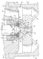
Fig. 2 is the local amplification view of the nozzle assembly of spray gun shown in Figure 1, and wherein needle is in the closed position;
Fig. 3 is and the similar spray gun shown in Figure 1 and the vertical sectional view of nozzle assembly, but its needle is another kind of form; With
Fig. 4 is the schematic diagram that has shown nozzle assembly shown in Figure 3, wherein has with what solid line was represented to close the relative less needle of closing with the size as shown in Figure 2 that is represented by dotted lines of needle.
Although the present invention can carry out various modifications and can have alternative constructions, expressed illustrative embodiment more of the present invention in the accompanying drawings, these embodiment will be explained in greater detail below.Yet should be appreciated that the present invention is not limited to disclosed concrete form, on the contrary, the present invention has covered all modifications, alternative constructions and the equivalent in spiritual essence of the present invention and scope.
The specific embodiment
Now in more detail with reference to the accompanying drawings, shown among the figure that according to injection apparatus 10 of the present invention, it comprises the spray gun 11 with nozzle assembly 12.The basic structure of spray gun 11 and mode of operation are known in this area, and for example shown in above-mentioned United States Patent (USP) 5707010, this patent is incorporated herein by reference.The total of spray gun 11 and mode of operation only should be understood that an example of the injection apparatus that has adopted nozzle assembly of the present invention is described.
Shown spray gun 11 comprises main casing 14, main casing 14 axially supports and closes needle 15, and has the fluid intake 16 that links to each other with fluid source to be sprayed and the auxiliary fluid that for example a links to each other inlet 18 with compressed air source, so that help fluid atomizing to be sprayed, and make needle 15 between the ON/OFF position, carry out in check axially-movable.
This shell 14 comprise by connect in the screw thread 19 interconnect be generally columniform procapsid part 14a and back housing portion 14b.Be formed with fluid intake 16 and auxiliary fluid inlet 18 on the procapsid part 14a, fluid intake 16 communicates with the central fluid channel 20 that centers on needle 15 simultaneously.Needle 15 is long cylindrical members, and it passes housing 14 coaxially and extends in the nozzle assembly 12.Needle 15 passes the opening 21 in the procapsid part 14a, and is supported to move back and forth by annulus 22, and an end of annulus 22 is supported in the front casing section 14a, and the other end is installed in the rear end of housing parts 14a by screw thread clamp nut 24 supports.Be provided with O-ring seal 25 at the two ends of stop sleeve 22.
In order to operate needle 15, back housing portion 14b has driven plunger assembly 28, and at the outside and the end wall of back housing portion 14b or the compression spring 29 between the shoulder of piston component 28.Piston component 28 comprises piston 30 and flexible cup seal ring 31, and it forms slipper seal with the inner surface of the cylindrical hole 32 that is positioned at back housing portion 14b coaxially and engages.Sealing ring 31 is fixed on the piston component by a pair of clamping ring or clamping washer 34,35, and this fixes by the locking cap 36 on the back bar part 38 that is screwed in piston 30 clamping ring or clamping washer 34,35.The enlarged end 39 of needle 15 is sandwiched between the end wall of the outer end of piston rod portion 38 and locking cap 36, thereby links to each other with piston 30.Therefore, needle 15 moves on housing 14 axial directions according to the selectivity axially-movable of piston component 28.
As illustrated in fig. 1 and 2, nozzle assembly 12 comprises and is generally columniform nozzle body 45, is installed in the hole part or the abaculus 46 of the outlet side of nozzle body 45 with one heart, the gas cap of installing around the outlet side of hole part 46 48.Nozzle body 45 is fixed on the front end of gun case 14 by the threaded rod 49 that can engage with fluid passage 20.Nozzle body 45 comprises the central axial fluid passage 50 that is connected with the fluid passage 20 of housing, and one or more connections are from the auxiliary fluid such as the compressed-air actuated passage 51 of circulating line 52, and circulating line 52 enters the mouth by passage 54 in the gun case and auxiliary fluid (being air) and 18 links to each other.The air duct 51 of nozzle body communicates with chamber or pipeline 53 again, and its gas cap 48 by the downstream that centers on nozzle body 45 forms.Gas cap 48 closely cooperates with the end of nozzle body 45, and fixing by the nut 55 that engages and be screwed on the end of nozzle body 45 with gas cap flange 56.
This hole part 46 comprises the hole part main body 59 with the fore-end 60 that has extended and formed fluid discharge outlet 61 forward.Hole part main body 59 press fit in the fluid passage 50 of nozzle body 45, and its location outer rim 62 forms relation close to each other with the built-in annular rim 64 of nozzle body 45.The fore-end 60 of hole part main body 59 extends outside nozzle body 45, and enters and pass the central opening 65 of gas cap 48.The diameter of the diameter ratio open 65 of fore-end 60 is smaller, has formed looping pit 66, can be parallel to the fluid of discharging from outlet 61 and discharges vaporific fluid such as compressed air.This gas cap 48 also comprises the passage 68 of a plurality of circumferentially spaceds, and it also communicates with pipeline or air cavity 53, the spraying of being discharged with further atomizing, formation and guiding.
For reaching best jet performance and prevent to leak when in the closed position closing needle 15, the important point is that the supporting end of needle 15 and hole part 46 should be designed to realize that reliable fluid closes.As implied above, produced the problem of manufacturing and field maintenance and replacing up to now in this regard.
According to the present invention, the hole part is designed to and can engages with the supporting that needle forms metal-metal, accurately and with one heart making needle in the closed position, and when closing for needle provides elastic packing, although in the supporting of metal-metal engages, have less tolerance variations or defective.For this reason, shown hole part 46 has formed the formed first inner conical valve seat 70 by frusto-conical face 70a, and frusto-conical face 70a shrinks towards downstream direction, and intersects with the second frusto-conical face 70b.As example, the first frusto-conical face 70a can form about 30 ° angle with the central axis of hole part, and the second frusto-conical face 70b can form about 20 ° angle with the central axis of hole part.
As illustrated in fig. 1 and 2, needle 15 has less diameter, be generally about 0.093 inch, and has a supporting end 74 that forms by the first frusto-conical face 74a, the first frusto-conical face 74a and the second frusto-conical face 74b intersect, between has formed the annular support shoulder 74c of sharp-pointed or small radii, so that engage with first conical valve seat 70 when needle 15 is in the closed position.This needle supporting shoulder 74c engages with the first frusto-conical face 70a of valve seat 70, can with one heart and accurately needle 15 be positioned bearing position, and form the metal-metal contact, and provide circumferential seal between pin 14 and area supported 70a.As a specific example, the longitudinal axis of surperficial 74a and pin forms about 15 ° angle, and surperficial 74b axis therewith forms about 45 ° angle.In this case, needle 15 also has the fore-end 75 of elongation at its far-end, and the big I of its diameter makes it can extend through outlet 61 when needle 15 is supported, so that clear up.Those skilled in the art will appreciate that and to adopt various needle end construction, engage so that make needle form accurate metal-metal with first valve seat 70.
According to the present invention, hole part 46 also comprises the elastic sealing element 78 of annular, although in needle and valve seat, have wearing and tearing or less tolerance variations, but in the process that valve needle movements seals with the more reliable fluid of formation to the closed position, seal 78 still can form effective fluid sealing with the needle 15 that separates with seal, and this is that metal-metal supporting by needle 15 and valve seat 70 contacts and sets up.The elastic seal ring 78 of this annular adopts the form of the O-ring seals of the upstream extremity that is installed in close valve seat 70.In this case, O-ring seals 78 is fixed on the counterbore 80 formed outward extending radially shoulders 79 by the upstream extremity of hole part main body 59.O-ring seals 78 is crushed on the shoulder 79, and the annular fixing members 81 that press fit in the counterbore 80 of hole part main body 59 fix, and makes O-ring seals produce radially inner distortion in valve needle movements during to the closed position, thereby engages with needle 15.For guaranteeing that elastic sealing element 78 fixes and control when mounted its radial deformation reliably, fixture 81 has radially shoulder 82, and it limits the pre-position in the counterbore 80 that fixture 81 inwardly is press fitted into hole part main body 59.Fixture 81 also has taper or conical end face 84, and it has formed and has been used for reliably the fixedly more sharp-pointed ring edge point 84a of O-ring seals 78.
Should be appreciated that, at needle 15 open position from behind in the motion of top valve closed position, the supporting end of needle especially annular support shoulder 74c is directed in the valve seat 70 of hole part, formation can be accurately and needle 15 metal-metal supportings in the closed position is contacted, and this supporting shoulder 74c engages with the first frusto-conical face 70a of valve seat 70.Simultaneously, the radially inside ledge of elastic sealing element 78 will contact with the conical bearing end of needle, and support the frusto-conical face 74a formation sealed engagement of upstream end in the part of hole with the metal-metal of needle.The metal-metal supporting that those skilled in the art will appreciate that needle 15 and valve seat 70 engages and needle is felt relieved and is positioned the closed position, and has formed the first fluid sealing.Elastic ring seal 78 provides second fluid sealing around needle 15 when needle 15 is in the closed position, thereby prevents from more reliably to leak, although exist tolerance variations or blemish in the metal-metal supporting of hole part inner valve needle.Therefore, needle and hole part multi-sealed contacts is not only providing more reliable valve to close in each operation cycle, also can be adjusted in issuable surface deviation and defective in the original manufacturing of hole part or the on-the-spot replacing process simultaneously.
According to the present invention, hole part 46 can be used to have the spray gun of the needle 15 of different size effectively.Fig. 3 with reference to as example represented spray gun same as described above 11 and nozzle assembly 12 among the figure, but spray gun 11 has the needle 85 of large-size, and for example its diameter is 0.125 inch.In this case, needle 85 has supporting end 86, the first frusto-conical face 86a and the second frusto-conical face 86b that are formed by the first frusto-conical face 86a and intersects, and has formed the supporting shoulder 86c that is positioned between the two.As example, surperficial 86a can form about 15 ° angle with the axis of needle, and surperficial 86b axis therewith forms about 45 ° angle.In addition, be appreciated that needle 85 can have other supporting end structure, comprise that those have the cleaning part of extending forward.
For realizing feature of the present invention, hole part 46 can be effectively be directed to the supporting that forms metal-metal at some place, the upstream of second elastic packing that is formed by elastic sealing element 78 with the supporting end 86 of needle 85 and engages.For this reason, retainer ring 81 has the annular lip 88 that extends internally at front end, it has formed sealing shoulder 88a, can be effectively preceding supporting end 86 guiding of needle 85 being formed accurate and concentric supporting engages, in this example, the supporting of metal-metal is bonded between the frusto-conical face 86a of the shoulder 88 of retainer ring 81 and needle and forms.In this case, the distance that the O-ring seals 86 of hole part 46 extends radially inwardly is bigger than the sealing shoulder 88a's of retainer ring 81, and forms elastic packing with the downstream taper seat 86b of needle 85 and contact.Therefore, similar to the embodiment among Fig. 1 and 2, when needle 85 was in the closed position, hole part 46 formed multi-metal-metal and flexible sealed engagement with needle, more reliable fluid sealing is provided, can have regulated tolerance or blemish in the metal-metal supporting simultaneously.
Those skilled in the art it can also be appreciated that the hole part 46 of nozzle assembly of the present invention make field maintenance and change more convenient, make simultaneously to the stock require minimum.At first, hole part 46 can carry out the scene as required effectively to be changed, and can regulate the tolerance variations or the wearing and tearing of needle simultaneously by elastic sealing element.And, because the hole part can use with the needle of different size, as Fig. 2,3 with (Fig. 4 is identical with Fig. 3, but needle 85 dots) shown in 4, can reduce requirement significantly to the stock.Needn't be each size or all types of independent hole parts of needle outfit.As the skilled personnel to understand, the unique location of elastic sealing element 78 and installation also make the hole part to use with the needle of various different sizes and type.
Claims (38)
1. injection apparatus comprises: nozzle body, and it has the fluid passage that can link to each other with compressed fluid source to be sprayed; Be fixed on the nozzle assembly on the described nozzle body, its bootable fluid enters predetermined jet mode from described fluid passage; Needle with supporting end, it can be return open position and prevent that fluid from optionally moving between the closed position that described nozzle assembly is discharged what the permission fluid in the described nozzle body was discharged from described nozzle assembly, described nozzle assembly has formed valve seat, the supporting part that can hold described needle when being in described needle closed position, described valve seat comprise and can and accurately be positioned at the rigidity valve seat of described closed position and can form the elastic part that fluid seals with the supporting part resilient engagement of described needle and around described supporting part when described needle is in described closed position the centering of described needle.
2. injection apparatus according to claim 1, it is characterized in that, described nozzle assembly comprises the hole part main body that has formed fluid discharge outlet and described rigidity valve seat, and described flexible valve seat part is formed by the cyclic spring seal that is fixed in the part main body of described hole.
3. injection apparatus according to claim 2 is characterized in that, described elastic sealing element is an O-ring seals.
4. injection apparatus according to claim 2 is characterized in that, described needle and hole part main body are made of metal, and when described needle was in the closed position, the supporting part of described rigidity valve seat and needle formed metal-metal and contacts.
5. injection apparatus according to claim 2 is characterized in that described elastic sealing element is located at the upstream of described rigidity valve seat.
6. injection apparatus according to claim 2 is characterized in that described elastic sealing element is located at the downstream of described rigidity valve seat.
7. injection apparatus according to claim 2 is characterized in that, described device comprises the annular fixing member in the upstream extremity of being located at described hole part main body, is used for fixing described elastic sealing element.
8. injection apparatus according to claim 7 is characterized in that, described fixture engages with described elastic sealing element, and the described relatively hole of described elastic sealing element part main body radially inwardly is out of shape.
9. injection apparatus according to claim 2 is characterized in that, described hole part main body has formed the first rigidity valve seat in the downstream of described elastic sealing element, and described nozzle assembly has formed the second rigidity valve seat in the upstream of described elastic sealing element.
10. injection apparatus according to claim 9 is characterized in that, the distance that described elastic sealing element extends radially outwardly surpasses the described second rigidity valve seat.
11. injection apparatus according to claim 9, it is characterized in that, described device comprises the annular fixing member in the upstream extremity of being located at described hole part main body, be used for fixing described elastic sealing element, the described first rigidity valve seat is formed by contraction of direction towards downstream that is positioned at described hole part main body and the tapered channel that communicates with described outlet, and the described second rigidity valve seat is formed by described fixture.
12. injection apparatus according to claim 2, it is characterized in that, described hole part main body has the upstream counterbore, defines the radially ledge adjacent with the upstream extremity of described rigidity valve seat, and described elastic sealing element is fixed on the adjacent described radially ledge.
13. injection apparatus according to claim 12 is characterized in that, described elastic sealing element is fixed on the described radially ledge by the annular fixing member in the counterbore that is installed in described hole part main body, and described counterbore is round described needle.
14. injection apparatus according to claim 13 is characterized in that, described fixture has the taper downstream that has formed more sharp-pointed annular shoulder, and being used for joins to merging with described elastic sealing element is fixed in the installation site.
15. injection apparatus according to claim 11, it is characterized in that, the described first rigidity valve seat is formed by first frusto-conical portion of described hole part main body, and described first frusto-conical portion links to each other with second frusto-conical portion, and described second frusto-conical portion communicates with described outlet again.
16. injection apparatus according to claim 15 is characterized in that, the supporting part of described needle comprises and intersecting to form first and second frusto-conical portions that valve seat engages shoulder.
17. injection apparatus according to claim 2, it is characterized in that, described nozzle body comprises the air duct that links to each other with compressed air source, described nozzle assembly comprises the gas cap that is provided with around described hole part main body, described gas cap forms bootable described compressed-air actuated at least one air duct, discharges from described fluid discharge outlet with control and termination fluid.
18. injection apparatus according to claim 17 is characterized in that, described gas cap has formed first circular passage around described fluid discharge outlet, and the circumferential air passage on a plurality of radially outer direction that is arranged on described circular passage.
19. nozzle assembly, can install and be used to have the injection apparatus of the needle of different size, flow and discharge by described nozzle assembly with the control fluid, described nozzle assembly comprises: the nozzle body that has formed fluid discharge outlet, when the needle of the injection apparatus that described nozzle assembly is installed is shown in an open position, fluid can be discharged by described fluid discharge outlet, and when described needle was in the closed position, fluid was closed; Be installed in the elastic sealing element in the described nozzle body, when described needle is in described closed position, described elastic sealing element can engage with described needle, and around the sealing of described needle formation fluid, described nozzle body has formed the first rigidity valve seat, when the needle with first size is in the closed position, the described first rigidity valve seat can be felt relieved and accurately be located described needle with first size, described nozzle body has also formed the second rigidity valve seat, when the needle with second size that is different from described first size was in the closed position, the described second rigidity valve seat can be felt relieved and accurately be located described needle with second size.
20. nozzle assembly according to claim 19 is characterized in that, described elastic sealing element is located at the upstream of described first valve seat in the described nozzle body and the downstream of described second valve seat.
21. nozzle assembly according to claim 20 is characterized in that, described first valve seat is arranged to feel relieved and is accurately located the needle of diameter less than the needle diameter that is positioned at described second valve seat.
22. nozzle assembly according to claim 19, it is characterized in that, described nozzle body comprises the hole part main body that has formed described fluid discharge outlet and at least one described rigidity valve seat, and the interior annular fixing member of upstream extremity of being located at described hole part main body, is used for fixing described elastic sealing element.
23. nozzle assembly according to claim 22 is characterized in that, described fixture engages with described elastic sealing element, and the described relatively hole of described elastic sealing element part main body radially inwardly is out of shape.
24. nozzle assembly according to claim 22 is characterized in that, described annular fixing member has formed the described second rigidity valve seat.
25. nozzle assembly according to claim 22, it is characterized in that, the described first rigidity valve seat is formed by contraction of direction towards downstream that is positioned at described hole part main body and the tapered channel that communicates with described outlet, and the described second rigidity valve seat is formed by described fixture.
26. nozzle assembly according to claim 25 is characterized in that, the described second rigidity valve seat is formed by the annular shoulder of described fixture.
27. nozzle assembly according to claim 26 is characterized in that, described annular shoulder is formed by the longitudinal end that extends internally of described fixture.
28. nozzle assembly according to claim 19, it is characterized in that, described assembly comprises the gas cap of installing near the downstream of described hole part main body, and described gas cap has formed at least one air duct, can guide compressed air and fluid to discharge by described fluid discharge outlet simultaneously.
29. nozzle assembly, can install and be used to have the injection apparatus of reciprocating needle, flow and discharge by described nozzle assembly with the control fluid, described nozzle assembly comprises the nozzle body that has formed fluid discharge outlet, when the needle of the injection apparatus that described nozzle assembly is installed is shown in an open position, fluid can be discharged by described fluid discharge outlet, when described needle is in the closed position, fluid is closed, described nozzle body has formed the first rigidity valve seat, when described needle was in described closed position, the described first rigidity valve seat can be felt relieved and accurately be located described needle; Be installed in the elastic sealing element in the described nozzle body, when described needle is in described closed position, described elastic sealing element and needle resilient engagement, and around the sealing of described needle formation fluid.
30. nozzle assembly according to claim 29 is characterized in that, described elastic sealing element is located at the upstream of the described rigidity valve seat in the described nozzle body.
31. nozzle assembly according to claim 29 is characterized in that, described elastic sealing element is located at the downstream of the described rigidity valve seat in the described nozzle body.
32. nozzle assembly according to claim 29 is characterized in that, described nozzle body has formed the first rigidity valve seat in the downstream that is positioned at described elastic sealing element and has been positioned at the second rigidity valve seat of the upstream of described elastic sealing element.
33. nozzle assembly according to claim 32 is characterized in that, described second valve seat can be felt relieved effectively and accurately be located the needle of diameter greater than described first valve seat.
34. injection apparatus according to claim 29 is characterized in that, described nozzle body comprises the hole part main body that forms described fluid discharge outlet and described rigidity valve seat.
35. injection apparatus according to claim 34 is characterized in that, described device comprises the annular fixing member in the upstream extremity of being located at described hole part main body, is used for fixing described elastic sealing element.
36. injection apparatus according to claim 35 is characterized in that, described fixture engages with described elastic sealing element, and the described relatively hole of described elastic sealing element part main body radially inwardly is out of shape.
37. injection apparatus according to claim 32, it is characterized in that, described nozzle body comprises the hole part main body that forms described fluid discharge outlet and described rigidity valve seat, with the annular fixing member in the upstream extremity of being located at described hole part main body, with fixing described elastic sealing element, the described first rigidity valve seat is formed by contraction of direction towards downstream that is positioned at described hole part main body and the tapered channel that communicates with described outlet, and the described second rigidity valve seat is formed by described fixture.
38. injection apparatus according to claim 29, it is characterized in that, described nozzle body comprises the air duct that links to each other with compressed air source, described nozzle assembly comprises the gas cap that is provided with around described nozzle body, described gas cap forms at least one air duct, and bootable described compressed air and control and termination fluid are discharged from described fluid discharge outlet.
Applications Claiming Priority (2)
| Application Number | Priority Date | Filing Date | Title |
|---|---|---|---|
| US09/892138 | 2001-06-26 | ||
| US09/892,138 US6776360B2 (en) | 2001-06-26 | 2001-06-26 | Spray gun with improved needle shut-off valve sealing arrangement |
Publications (2)
| Publication Number | Publication Date |
|---|---|
| CN1394691A CN1394691A (en) | 2003-02-05 |
| CN100430147C true CN100430147C (en) | 2008-11-05 |
Family
ID=25399432
Family Applications (1)
| Application Number | Title | Priority Date | Filing Date |
|---|---|---|---|
| CNB021403600A Expired - Lifetime CN100430147C (en) | 2001-06-26 | 2002-06-26 | Spray gun with improved needle type cut-off valve sealing device |
Country Status (10)
| Country | Link |
|---|---|
| US (1) | US6776360B2 (en) |
| EP (1) | EP1270081B1 (en) |
| JP (1) | JP4330848B2 (en) |
| CN (1) | CN100430147C (en) |
| AT (1) | ATE426457T1 (en) |
| AU (1) | AU784945B2 (en) |
| CA (1) | CA2389940C (en) |
| DE (1) | DE60231677D1 (en) |
| DK (1) | DK1270081T3 (en) |
| ES (1) | ES2322940T3 (en) |
Families Citing this family (40)
| Publication number | Priority date | Publication date | Assignee | Title |
|---|---|---|---|---|
| US7640006B2 (en) * | 2001-10-03 | 2009-12-29 | Accenture Global Services Gmbh | Directory assistance with multi-modal messaging |
| US7762476B2 (en) * | 2002-08-19 | 2010-07-27 | Illinois Tool Works Inc. | Spray gun with improved atomization |
| US6808122B2 (en) * | 2002-08-19 | 2004-10-26 | Illinois Tool Works, Inc. | Spray gun with improved pre-atomization fluid mixing and breakup |
| US20050284957A1 (en) * | 2002-09-23 | 2005-12-29 | Spraying Systems Co. | External mix air atomizing spray nozzle assembly |
| US6935577B2 (en) * | 2003-02-28 | 2005-08-30 | Illinois Tool Works Inc. | One-piece fluid nozzle |
| JP2006521205A (en) * | 2003-03-27 | 2006-09-21 | スプレイング システムズ カンパニー | Modular spray gun with multiple control modules |
| US7883026B2 (en) | 2004-06-30 | 2011-02-08 | Illinois Tool Works Inc. | Fluid atomizing system and method |
| US7926733B2 (en) * | 2004-06-30 | 2011-04-19 | Illinois Tool Works Inc. | Fluid atomizing system and method |
| BRPI0419248B1 (en) | 2004-12-28 | 2014-12-02 | Pirelli | METHOD AND APPARATUS FOR MANUFACTURING VEHICLE WHEEL TIRE |
| US8389062B2 (en) | 2005-05-12 | 2013-03-05 | Spraying Systems Co. | Spraying system for progressive spraying of non-rectangular objects |
| JP4958412B2 (en) * | 2005-07-08 | 2012-06-20 | 株式会社ウエノコーポレーション | Painting equipment |
| KR100554723B1 (en) | 2005-12-08 | 2006-02-24 | 주식회사 삼진정밀 | Pilot-relief valve |
| FR2896293B1 (en) * | 2006-01-17 | 2010-08-13 | Schrader Sas | MECHANISM FOR OPENING OR CLOSING A VALVE HAVING TWO CLOSURE POSITIONS |
| RU2329873C2 (en) * | 2006-08-24 | 2008-07-27 | Андрей Леонидович Душкин | Liquid sprayer |
| US20080179554A1 (en) * | 2007-01-29 | 2008-07-31 | Finn Clifford J | Dispensing Gun Valve Member And Dispensing Gun Formed Therewith |
| KR200437997Y1 (en) * | 2007-02-08 | 2008-01-11 | 손형모 | Sealing structure for valve |
| US9272295B2 (en) * | 2008-02-12 | 2016-03-01 | Kohler Co. | Sprayer assembly |
| GB0903275D0 (en) | 2009-02-26 | 2009-04-08 | Earlex Ltd | Spray gun |
| CN101816986B (en) * | 2010-04-27 | 2012-11-07 | 杭州华达喷射真空设备有限公司 | Adjustable ejector nozzle and method for forming jet linear fluid |
| US8939387B2 (en) | 2010-05-03 | 2015-01-27 | Chapin Manufacturing, Inc. | Spray gun |
| GB2491929B (en) | 2011-06-17 | 2017-07-26 | Earlex Ltd | Spray gun |
| US8524312B2 (en) * | 2011-11-16 | 2013-09-03 | Csl Silicones Inc. | Applicator for spraying elastomeric materials |
| WO2014069326A1 (en) * | 2012-10-29 | 2014-05-08 | 東海ゴム工業株式会社 | Spray gun |
| CN103292011B (en) * | 2013-07-01 | 2015-01-14 | 核工业理化工程研究院 | Pneumatic oil injection cut-off valve |
| NL2011640C2 (en) * | 2013-10-18 | 2015-04-23 | Kimman Process Solutions B V | Sampling device. |
| US20150375986A1 (en) * | 2014-06-27 | 2015-12-31 | Gssc, Inc. | Rod Valve |
| CN104437940A (en) * | 2014-12-24 | 2015-03-25 | 深圳市沃尔核材股份有限公司 | Controllable leakage stop shower nozzle |
| US10392786B2 (en) * | 2015-01-19 | 2019-08-27 | Moen Incorporated | Electronic plumbing fixture fitting with electronic valve including piston and seat |
| US10213795B2 (en) | 2015-05-07 | 2019-02-26 | Nordson Corporation | Fluid dispensing apparatus and methods utilizing a resilient nozzle |
| DE102015008659B4 (en) * | 2015-07-03 | 2019-06-19 | Dürr Systems Ag | Coating agent valve and rotary atomizer |
| DE102015008661A1 (en) | 2015-07-03 | 2017-01-05 | Dürr Systems Ag | needle valve |
| US9915389B1 (en) * | 2017-02-06 | 2018-03-13 | Emerson Process Management Regulator Technologies, Inc. | Mechanically-retained sealing disks for use with fluid regulators |
| DE102017122493A1 (en) * | 2017-09-27 | 2019-03-28 | Dürr Systems Ag | Applicator with small nozzle spacing |
| DE102017122495A1 (en) | 2017-09-27 | 2019-03-28 | Dürr Systems Ag | Applicator with a small nozzle spacing |
| CN109225708A (en) * | 2018-08-23 | 2019-01-18 | 浙江荣鹏气动工具有限公司 | A kind of adjustable sealing structure on high-pressure airless spraying gun |
| CN110215982A (en) * | 2019-06-03 | 2019-09-10 | 吉林市新大科机电技术有限责任公司 | A kind of fluidized bed counter jet mill mill porous bottom spray nozzle device in room |
| DE102020107044A1 (en) | 2020-03-13 | 2021-09-16 | André Hiessl | Spray device for applying small amounts of a spray medium |
| CN112058515B (en) * | 2020-08-10 | 2022-03-04 | 浙江虹达特种橡胶制品有限公司 | Manufacturing method and application method of perfume slow-release device used in spray head |
| CN113309881B (en) * | 2021-05-22 | 2023-08-11 | 上海开维喜阀门有限公司 | Binary channels valve with high sealing performance |
| CN115944535B (en) * | 2023-03-15 | 2023-06-13 | 江中药业股份有限公司 | Spray gun device for medicine granulator or coating machine |
Citations (7)
| Publication number | Priority date | Publication date | Assignee | Title |
|---|---|---|---|---|
| DE1152857B (en) * | 1961-01-11 | 1963-08-14 | Ruhrstahl Ag | Valve with a hard and flexible seal |
| FR1351077A (en) * | 1963-03-11 | 1964-01-31 | Double closing valve, to intercept liquids, more particularly for central heating installations | |
| EP0109268A2 (en) * | 1982-11-10 | 1984-05-23 | Diversey Engineering (Europe) Limited | Spray gun |
| EP0116704A1 (en) * | 1983-02-10 | 1984-08-29 | Dynapac Aktiebolag | Spray bar valve |
| US5344078A (en) * | 1993-04-22 | 1994-09-06 | Ransburg Corporation | Nozzle assembly for HVLP spray gun |
| US5618025A (en) * | 1996-05-23 | 1997-04-08 | Fisher Controls International, Inc. | Protected soft seat with secondary hard seat |
| US5707010A (en) * | 1995-09-29 | 1998-01-13 | Spraying Systems Co. | Controllable spray nozzle assembly |
Family Cites Families (14)
| Publication number | Priority date | Publication date | Assignee | Title |
|---|---|---|---|---|
| US2929401A (en) * | 1957-03-11 | 1960-03-22 | Herbert M Cowan | Check valve with plural seating |
| US3233863A (en) * | 1963-04-15 | 1966-02-08 | Pressure Products Ind Inc | Valve having multiple seating surfaces |
| US4014510A (en) * | 1975-09-05 | 1977-03-29 | Midcon Pipeline Equipment Co. | Pilot valve |
| DE8231663U1 (en) * | 1982-11-11 | 1983-08-18 | Hermann Behr & Sohn Gmbh & Co, 7121 Ingersheim | NOZZLE WITH CONNECTING COAXIAL ARRANGEMENT FOR A COLOR SPRAYING DEVICE |
| US4834338A (en) * | 1988-02-05 | 1989-05-30 | Fisher Controls International, Inc. | High pressure flexible seat valve trim |
| DE4009168A1 (en) * | 1990-03-22 | 1991-09-26 | Walther Spritz Lackiersyst | SPRAY GUN |
| US5123436A (en) * | 1990-06-27 | 1992-06-23 | Mallory, Inc. | Plunger-type fuel pressure regulator |
| DE4213826A1 (en) * | 1991-05-08 | 1992-11-12 | Walther Spritz Lackiersyst | Spray gun for print - has closed nozzle pin tip, spring-loaded on sealing seat in spray nozzle, to block spray material |
| US5370357A (en) * | 1993-12-03 | 1994-12-06 | Ohmeda Inc. | Needle valve with deformable seal |
| US5462204A (en) * | 1994-03-29 | 1995-10-31 | Rhh Foam Systems, Inc. | Foam dispensing gun |
| DE19544016A1 (en) * | 1995-11-27 | 1997-05-28 | Klaschka Gmbh & Co | Atomizing head for liquids and device for spraying workpieces with liquids with such atomizing heads |
| US5878993A (en) | 1997-03-27 | 1999-03-09 | St. Germain; Stephen V. | Shielded globe valve seal mechanism |
| US5899387A (en) * | 1997-09-19 | 1999-05-04 | Spraying Systems Co. | Air assisted spray system |
| US6283152B1 (en) | 1999-03-01 | 2001-09-04 | Cor-Val, Inc. | Multiple sleeve valve assembly |
-
2001
- 2001-06-26 US US09/892,138 patent/US6776360B2/en not_active Expired - Lifetime
-
2002
- 2002-06-10 CA CA2389940A patent/CA2389940C/en not_active Expired - Lifetime
- 2002-06-17 AU AU48819/02A patent/AU784945B2/en not_active Expired
- 2002-06-25 EP EP02254448A patent/EP1270081B1/en not_active Expired - Lifetime
- 2002-06-25 DK DK02254448T patent/DK1270081T3/en active
- 2002-06-25 DE DE60231677T patent/DE60231677D1/en not_active Expired - Lifetime
- 2002-06-25 AT AT02254448T patent/ATE426457T1/en active
- 2002-06-25 ES ES02254448T patent/ES2322940T3/en not_active Expired - Lifetime
- 2002-06-26 CN CNB021403600A patent/CN100430147C/en not_active Expired - Lifetime
- 2002-06-26 JP JP2002186526A patent/JP4330848B2/en not_active Expired - Lifetime
Patent Citations (7)
| Publication number | Priority date | Publication date | Assignee | Title |
|---|---|---|---|---|
| DE1152857B (en) * | 1961-01-11 | 1963-08-14 | Ruhrstahl Ag | Valve with a hard and flexible seal |
| FR1351077A (en) * | 1963-03-11 | 1964-01-31 | Double closing valve, to intercept liquids, more particularly for central heating installations | |
| EP0109268A2 (en) * | 1982-11-10 | 1984-05-23 | Diversey Engineering (Europe) Limited | Spray gun |
| EP0116704A1 (en) * | 1983-02-10 | 1984-08-29 | Dynapac Aktiebolag | Spray bar valve |
| US5344078A (en) * | 1993-04-22 | 1994-09-06 | Ransburg Corporation | Nozzle assembly for HVLP spray gun |
| US5707010A (en) * | 1995-09-29 | 1998-01-13 | Spraying Systems Co. | Controllable spray nozzle assembly |
| US5618025A (en) * | 1996-05-23 | 1997-04-08 | Fisher Controls International, Inc. | Protected soft seat with secondary hard seat |
Also Published As
| Publication number | Publication date |
|---|---|
| CA2389940A1 (en) | 2002-12-26 |
| ATE426457T1 (en) | 2009-04-15 |
| ES2322940T3 (en) | 2009-07-02 |
| US6776360B2 (en) | 2004-08-17 |
| DK1270081T3 (en) | 2009-06-02 |
| AU4881902A (en) | 2003-01-02 |
| US20020195505A1 (en) | 2002-12-26 |
| EP1270081B1 (en) | 2009-03-25 |
| CN1394691A (en) | 2003-02-05 |
| JP4330848B2 (en) | 2009-09-16 |
| JP2003062490A (en) | 2003-03-04 |
| DE60231677D1 (en) | 2009-05-07 |
| AU784945B2 (en) | 2006-08-03 |
| CA2389940C (en) | 2012-02-21 |
| EP1270081A3 (en) | 2004-03-10 |
| EP1270081A2 (en) | 2003-01-02 |
Similar Documents
| Publication | Publication Date | Title |
|---|---|---|
| CN100430147C (en) | Spray gun with improved needle type cut-off valve sealing device | |
| CN1764502B (en) | Modular spray gun with multiple control modules | |
| US5154259A (en) | Lubricating device for knitting machine | |
| US7789325B2 (en) | Air atomizing spray nozzle with magnetically actuated shutoff valve | |
| KR970061374A (en) | Solution discharging device and manufacturing method thereof | |
| KR20160115059A (en) | The valve seat device having a removable way ball valve seat surface cleaning means | |
| JP6701212B2 (en) | Fuel injector | |
| US6676047B1 (en) | Double sealing valve | |
| US20130020414A1 (en) | Spray gun nozzle tip with integrated seal and auto aligining fluid path | |
| KR20010020200A (en) | Spray gun | |
| KR20010029778A (en) | A check-valve for a water jet pump of a water jet type loom | |
| CA1285457C (en) | Valve | |
| CN110671249B (en) | Distribution pump plunger with oil outlet valve and working method thereof | |
| KR20210027216A (en) | Valve and system for application of covering product comprising such a valve | |
| RU2142081C1 (en) | Radiator valve | |
| KR930003051B1 (en) | Quantitative distributing valve | |
| KR19990045381A (en) | Sealing device for metering valve for internal combustion engine fuel injector | |
| CN111120171A (en) | Fuel injection valve assembly | |
| CN112912288A (en) | Cleaning device with reciprocating piston | |
| KR100287310B1 (en) | Fuel Injection Nozzle for Internal Combustion Engines | |
| CN110529879A (en) | Two-phase fuel nozzle | |
| KR102067212B1 (en) | A Dispensing Device | |
| KR20170084667A (en) | Automatic pressure control valve of power sprayer | |
| CA2150427A1 (en) | Fuel injection nozzle | |
| US20230366478A1 (en) | Valve device for controlled passage of a medium, in particular in the high-pressure range |
Legal Events
| Date | Code | Title | Description |
|---|---|---|---|
| C06 | Publication | ||
| PB01 | Publication | ||
| C10 | Entry into substantive examination | ||
| SE01 | Entry into force of request for substantive examination | ||
| C14 | Grant of patent or utility model | ||
| GR01 | Patent grant | ||
| C56 | Change in the name or address of the patentee |
Owner name: SPRAYING SYSTEM CO., LTD. Free format text: FORMER NAME: SPRAY SYSTEMS INC. |
|
| CP01 | Change in the name or title of a patent holder |
Address after: Illinois State Patentee after: SPRAYING SYSTEMS Co. Address before: Illinois State Patentee before: SPRAYING SYSTEMS CO. |
|
| CX01 | Expiry of patent term | ||
| CX01 | Expiry of patent term |
Granted publication date: 20081105 |