CN100429832C - Electric connector assembly - Google Patents
Electric connector assembly Download PDFInfo
- Publication number
- CN100429832C CN100429832C CNB2004100660760A CN200410066076A CN100429832C CN 100429832 C CN100429832 C CN 100429832C CN B2004100660760 A CNB2004100660760 A CN B2004100660760A CN 200410066076 A CN200410066076 A CN 200410066076A CN 100429832 C CN100429832 C CN 100429832C
- Authority
- CN
- China
- Prior art keywords
- connector
- insulating body
- grab
- electric coupler
- coupler component
- Prior art date
- Legal status (The legal status is an assumption and is not a legal conclusion. Google has not performed a legal analysis and makes no representation as to the accuracy of the status listed.)
- Expired - Fee Related
Links
Images


Classifications
-
- H—ELECTRICITY
- H01—ELECTRIC ELEMENTS
- H01R—ELECTRICALLY-CONDUCTIVE CONNECTIONS; STRUCTURAL ASSOCIATIONS OF A PLURALITY OF MUTUALLY-INSULATED ELECTRICAL CONNECTING ELEMENTS; COUPLING DEVICES; CURRENT COLLECTORS
- H01R13/00—Details of coupling devices of the kinds covered by groups H01R12/70 or H01R24/00 - H01R33/00
- H01R13/62—Means for facilitating engagement or disengagement of coupling parts or for holding them in engagement
- H01R13/627—Snap or like fastening
- H01R13/6275—Latching arms not integral with the housing
-
- H—ELECTRICITY
- H01—ELECTRIC ELEMENTS
- H01R—ELECTRICALLY-CONDUCTIVE CONNECTIONS; STRUCTURAL ASSOCIATIONS OF A PLURALITY OF MUTUALLY-INSULATED ELECTRICAL CONNECTING ELEMENTS; COUPLING DEVICES; CURRENT COLLECTORS
- H01R12/00—Structural associations of a plurality of mutually-insulated electrical connecting elements, specially adapted for printed circuits, e.g. printed circuit boards [PCB], flat or ribbon cables, or like generally planar structures, e.g. terminal strips, terminal blocks; Coupling devices specially adapted for printed circuits, flat or ribbon cables, or like generally planar structures; Terminals specially adapted for contact with, or insertion into, printed circuits, flat or ribbon cables, or like generally planar structures
- H01R12/70—Coupling devices
- H01R12/71—Coupling devices for rigid printing circuits or like structures
- H01R12/712—Coupling devices for rigid printing circuits or like structures co-operating with the surface of the printed circuit or with a coupling device exclusively provided on the surface of the printed circuit
- H01R12/716—Coupling device provided on the PCB
Abstract
The present invention relates to an electric connector assembly (10) which is used for electrically connecting two circuit boards. The present invention comprises a first connector (20) and a second connector (30) butted with the first connector, wherein the first connector comprises a first insulation body (200) and a plurality of first conductive terminals (210) contained in the first insulation body; the second connector comprises a second insulation body (300) and a plurality of second conductive terminals (320) arranged in the second insulation body to be correspondingly inserted with the first conductive terminal. Both sides of the first insulation body are respectively provided with a clamping hook (220), and both sides of the second insulation body are correspondingly provided with a protrusion (314) used for locking the clamping hook. When the first connector is butted with the second connector, the clamping hook and the protrusion are stably buckled to prevent the first connector falling off from the second connector and to improve the reliability of the electrical connection of the electric connector assembly.
Description
[technical field]
The present invention relates to a kind of electric coupler component, especially a kind of in order to electrically connect the Board-to-Board Electrical Connector of two circuit boards.
[background technology]
In order to realize the stable transfer of data and signal between the circuit board, Board-to-Board Electrical Connector is provided with button usually and holds mechanism on first connector of butt joint mutually and second connector, to increase the retain strength after the butt joint of first connector and second connector.
Prior art has disclosed multiplely to be had button and holds the Board-to-Board Electrical Connector of mechanism, relevant patent see also on March 30th, 1999 bulletin No. the 5th, 888,077, United States Patent (USP) and in No. the 5th, 885,093, the United States Patent (USP) of bulletin on May 23rd, 1999.The Board-to-Board Electrical Connector that above-mentioned patent discloses comprises first connector and second connector that docks with first connector, be respectively equipped with projection on the end walls of first connector, the corresponding fluting that offers this projection of snap close on the end walls of second connector, the fastening of borrowing projection and fluting prevents that to increase the retain strength after first connector and second connector dock first connector relative second electric connector on the butt joint direction from producing motion.
But, there is following shortcoming in the Board-to-Board Electrical Connector that above-mentioned prior art discloses: the butt joint of first connector and second connector only depends on the frictional force between the fluting of the projection of first connector and second connector to keep, because insulating body smooth surface and be easy to produce distortion, therefore, retain strength between butt joint back first connector and second connector is difficult to be guaranteed, first connector comes off in second connector easily, influences the reliability that Board-to-Board Electrical Connector electrically connects.
Therefore, need a kind of novel Board-to-Board Electrical Connector of design to overcome the shortcoming of above-mentioned prior art.
[summary of the invention]
The technical problem to be solved in the present invention provides a kind of have preferable retain strength and the reliable electric coupler component that electrically connects performance.
For solving the problems of the technologies described above, electric coupler component of the present invention comprises first connector and second connector that docks with first connector.First connector comprises first insulating body and is placed in some first conducting terminals in first insulating body, second connector comprise second insulating body and be arranged in second insulating body, some second conducting terminals to peg graft with corresponding first conducting terminal.The first insulating body both sides are provided with grab, the corresponding protuberance that is provided with the locking grab in the second insulating body both sides.
With respect to prior art, electric coupler component of the present invention has the following advantages: the first insulating body both sides are provided with grab, the corresponding protuberance that is provided with the locking grab in the second insulating body both sides, when first connector and the butt joint of second connector, grab and protuberance can be stablized fastening, can provide preferable retain strength whereby, prevent that first connector from coming off in second connector, improve the reliability that electric coupler component electrically connects.
[description of drawings]
Below in conjunction with the drawings and specific embodiments, electric coupler component of the present invention is described in further detail.
Fig. 1 is the three-dimensional exploded view of electric coupler component of the present invention;
Fig. 2 is the assembly drawing of electric coupler component shown in Figure 1;
Fig. 3 is the partial sectional view of electric coupler component shown in Figure 2;
Fig. 4 is the partial enlarged drawing of the A of circle portion in the electric coupler component shown in Figure 3;
Fig. 5 be in the electric coupler component shown in Figure 1 first connector along the cutaway view of B-B line;
[embodiment]
See also shown in Figure 1, electric coupler component 10 of the present invention, in order to electrically connect two circuit boards (not shown), it comprises first connector 20 and second connector 30 that docks with first connector 20.
First insulating body 200 is by the integrated longitudinal structure of insulating material, and it comprises base portion 202 that is positioned at first insulating body, 200 both sides and the central boss 204 that protrudes out with respect to base portion 202.Central boss 204 offers some terminal grooves 206 that run through first insulating body 200, arrange by certain way, correspondingly in the terminal groove 206 contains some first conducting terminals 210.First conducting terminal, 210 1 ends extend the installed surface 208 of first insulating body 200, and to electrically connect circuit board, other end bifurcated in terminal groove 206 forms the grafting space, to accommodate corresponding second conducting terminal 320.
See also Fig. 4 and Fig. 5, the base portion 202 of first insulating body, 200 both sides is arranged with the grab 220 that extends in the same way with central boss 204, grab 220 with respect to the extended distance of base portion 202 less than the extended distance of central boss 204 with respect to base portion 202.Grab 220 is formed by the sheet metal forging and pressing of tool favorable elasticity, and is immobilizated in first insulating body 200 by injection mo(u)lding, and it comprises holding parts 222 and the holding section 224 that suspends of extending with holding parts 222 coplanes.The limit, two opposite sides of holding parts 222 is arranged with some hangnails 223, so that grab 220 more stably is immobilizated in first insulating body 200.Holding section 224 forms elasticity buckling parts 226 near free ends through punching press, and buckling parts 226 1 sides are connected on the holding section 224, and opposite side 224 breaks away from and holding section 224 generation elastic displacements relatively from the holding section.224 free end both sides, holding section are provided with lead angle 228, so that grab 220 inserts on second insulating body, 300 end walls 304 in the corresponding accepting groove of offering 306 smoothly.
In other execution modes of the present invention, buckling parts 226 also can be formed by the bending of grab 220 free ends; In addition, can also on the base portion 202 of first insulating body 200, offer the slit of accommodating grab 220 holding parts 222 earlier, then grab 220 is inserted in this slit, grab 220 stably is immobilizated in first insulating body 200 by means of the interference engagement between grab 220 holding parts 222 and the slot wall.
Please continue to consult shown in Figure 1, second connector 30 comprise second insulating body 300 and be mounted in second insulating body 300, with first connector 20 in corresponding first conducting terminal 210 some second conducting terminals 320 of pegging graft.
Second insulating body 300 is one-body molded by insulating material, and it comprises diapire 302 and the pair of end walls 304 of extending in the same way from diapire 302 two ends.End wall 304 is slightly larger than the extended distance of the central boss 204 of first insulating body 200 with respect to base portion 202 with respect to the distance that diapire 302 extends, distance between end wall 304 inboards is slightly larger than the length dimension of the central boss 204 of first insulating body 200, to guarantee the smooth butt joint between first connector 20 and second connector 30.Group is provided with some needle-likes on the diapire 302 of second insulating body 300, the arrangement mode of second conducting terminal, 320, the second conducting terminals 320 that runs through second insulating body, 300 diapires 302 is corresponding with the arrangement mode of first conducting terminal 210.Second conducting terminal, 320 1 ends and end wall 304 extend in the same way, and to peg graft with corresponding first conducting terminal 210, the other end extends the joint face 303 of second insulating body 300, to be electrically conducted with circuit board.
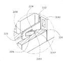
Please in conjunction with consulting Fig. 3 and Fig. 4, the end wall 304 of second insulating body 300 has suitable thickness, is respectively equipped with the accepting groove 306 of accommodating grab 220 on it.Accepting groove 306 runs through second insulating body 300 along end wall 304 direction of extension and extends and be provided with, and it comprises abutment walls 308, the pair of sidewalls 310 that extends in parallel from abutment walls 308 two ends, and contact wall 312 308 relative with abutment walls, that be connected sidewall 310.Contact wall 312 tops are provided with from contacting the protuberance 314 that wall 312 protrudes out to abutment walls 308, protuberance 314 comprises successively that from top to bottom guiding face 3140, self-aiming face 3140 ends are parallel to the perpendicular end surface 3142 that abutment walls 308 is extended downwards, and the horizontal bottom 3144 of extending from perpendicular end surface 3142 terminal horizontal, the spacing between perpendicular end surface 3142 and the abutment walls 308 less than grab 220 in the spacing between buckling parts 226 free ends and the holding section 224 under the nature.
The docking operation of electric coupler component 10 first connectors 20 of the present invention and second connector 30 is described: at first below with reference to Fig. 1, Fig. 2 and Fig. 3,304 of the end walls of central boss 204 insertions second insulating body 300 of first insulating body 200, and along the diapire 302 direction slippages of end wall 304 to second insulating body 300, second corresponding in first conducting terminal, 210 beginnings in first connector 20 and second connector 30 conducting terminal 320 is pegged graft; When first insulating body 200 when end wall 304 slides onto certain position, holding section 224 beginnings of grab 220 are against the abutment walls 308 of accepting groove 306, the lead angle 228 of grab 220 buckling partss 226 contacts with the sidewall 310 of accepting groove 306, and at this moment, the buckling parts 226 of grab 220 still in the raw; When buckling parts 226 slides onto when contacting with perpendicular end surface 3142, buckling parts 226 is subjected to the extruding of perpendicular end surface 3142 to produce strain and draws in to holding section 224 directions; At last, when perpendicular end surface 3142 is crossed in the free end slippage of buckling parts 226, buckling parts 226 borrows the strain of self towards launching away from holding section 224 directions, and return to nature, simultaneously, corresponding second conducting terminal 320 is fully pegged graft in first conducting terminal 210 in first connector 20 and second connector 30.
After first connector 20 and second connector 30 dock fully, the free end of grab 220 buckling partss 226 is connected on the horizontal bottom 3144 of protuberance 314 lower ends, thereby with first connector 20 and the 30 stable lockings of second connector, can prevent that first connector 20 from coming off in second connector 30, improve the reliability that electric coupler component 10 electrically connects.
Claims (9)
1. electric coupler component, it comprises first connector and second connector that docks with first connector, first connector comprises first insulating body and some first conducting terminals that are placed in first insulating body, second connector comprises second insulating body and is mounted in second insulating body, some second conducting terminals with corresponding grafting with first conducting terminal, it is characterized in that: the described first insulating body both sides respectively are provided with grab, the described second insulating body both sides are corresponding to be provided with the accepting groove that can accommodate grab, and is provided with the protuberance that protrudes into the grab that also can lock in it in the accepting groove.
2. electric coupler component according to claim 1 is characterized in that: described grab comprises holding parts and the holding section of extending with the holding parts coplane, and the holding section is provided with the elasticity buckling parts.
3. electric coupler component according to claim 2 is characterized in that: near the punch forming free end of holding section of described buckling parts, and the one side is connected on the holding section, and opposite side breaks away from from the holding section.
4. according to claim 2 or 3 described electric coupler components, it is characterized in that: the bilateral symmetry of described grab holding parts is provided with some hangnails.
5. electric coupler component according to claim 1, it is characterized in that: first insulating body comprises base portion that is positioned at the first insulating body both sides and the central boss that protrudes out with respect to base portion, second insulating body comprises diapire and the end wall that extends in the same way from the diapire two ends, be respectively equipped with described accepting groove on the end wall, described grab extends in the same way from base portion and central boss, and described protuberance relative set is in the accepting groove top.
6. electric coupler component according to claim 5 is characterized in that: described accepting groove runs through second insulating body along the end wall direction of extension and extends.
7. electric coupler component according to claim 5 is characterized in that: described grab with respect to the extended distance of base portion less than the extended distance of central boss with respect to base portion.
8. electric coupler component according to claim 3, it is characterized in that: described protuberance is provided with guiding face, the terminal perpendicular end surface of extending and supplying the described buckling parts of extruding of self-aiming face, and from the extension of perpendicular end surface terminal horizontal and for the horizontal bottom that fastens described buckling parts.
9. electric coupler component according to claim 2 is characterized in that: free end both sides, described holding section are provided with and can insert the interior lead angle of the second insulating body accepting groove smoothly for grab.
Priority Applications (2)
| Application Number | Priority Date | Filing Date | Title |
|---|---|---|---|
| CNB2004100660760A CN100429832C (en) | 2004-12-14 | 2004-12-14 | Electric connector assembly |
| US11/304,512 US7234957B2 (en) | 2004-12-14 | 2005-12-14 | Electrical connector assembly having locking mechanism |
Applications Claiming Priority (1)
| Application Number | Priority Date | Filing Date | Title |
|---|---|---|---|
| CNB2004100660760A CN100429832C (en) | 2004-12-14 | 2004-12-14 | Electric connector assembly |
Publications (2)
| Publication Number | Publication Date |
|---|---|
| CN1790815A CN1790815A (en) | 2006-06-21 |
| CN100429832C true CN100429832C (en) | 2008-10-29 |
Family
ID=36584588
Family Applications (1)
| Application Number | Title | Priority Date | Filing Date |
|---|---|---|---|
| CNB2004100660760A Expired - Fee Related CN100429832C (en) | 2004-12-14 | 2004-12-14 | Electric connector assembly |
Country Status (2)
| Country | Link |
|---|---|
| US (1) | US7234957B2 (en) |
| CN (1) | CN100429832C (en) |
Families Citing this family (10)
| Publication number | Priority date | Publication date | Assignee | Title |
|---|---|---|---|---|
| JP4947648B2 (en) * | 2007-06-18 | 2012-06-06 | Smk株式会社 | connector |
| US20090034164A1 (en) * | 2007-08-02 | 2009-02-05 | Dragonstate Technology Co., Ltd. | Anchor structure for electronic card connector pins |
| US7632131B2 (en) * | 2007-10-16 | 2009-12-15 | T-Conn Precision Corporation | Structure of electronic connector |
| TWM344595U (en) * | 2008-03-31 | 2008-11-11 | Hon Hai Prec Ind Co Ltd | Electrical connector |
| US8641442B2 (en) * | 2012-04-27 | 2014-02-04 | Anderson Power Products, Inc. | Compact latching mechanism for a mid-power electrical connector |
| CN203707415U (en) | 2014-01-26 | 2014-07-09 | 上海莫仕连接器有限公司 | Terminal |
| CN203707480U (en) * | 2014-01-26 | 2014-07-09 | 上海莫仕连接器有限公司 | Electric connection device |
| CN105811167B (en) * | 2016-05-31 | 2018-06-29 | 安费诺电子装配(厦门)有限公司 | connector module with self-locking structure |
| CN108321607A (en) * | 2017-01-14 | 2018-07-24 | 富士康(昆山)电脑接插件有限公司 | Electric connector |
| CN113078510B (en) * | 2021-03-10 | 2023-09-19 | 东莞立讯技术有限公司 | Connector assembly |
Citations (3)
| Publication number | Priority date | Publication date | Assignee | Title |
|---|---|---|---|---|
| US3394337A (en) * | 1966-08-15 | 1968-07-23 | Hughes Aircraft Co | Connector securing device |
| US6164989A (en) * | 1993-11-12 | 2000-12-26 | Glad; Paul H. | Adaptable communications connectors |
| CN2766373Y (en) * | 2004-12-15 | 2006-03-22 | 富士康(昆山)电脑接插件有限公司 | Electric connector assembly |
Family Cites Families (3)
| Publication number | Priority date | Publication date | Assignee | Title |
|---|---|---|---|---|
| TW417868U (en) * | 1998-11-06 | 2001-01-01 | Hon Hai Prec Ind Co Ltd | Auxiliary installation apparatus for electric card connector |
| TWI254498B (en) * | 2001-08-02 | 2006-05-01 | Hosiden Corp | Plug connector |
| WO2004036262A2 (en) * | 2002-10-16 | 2004-04-29 | Finisar Corporation, Llc | Transceiver latch mechanism |
-
2004
- 2004-12-14 CN CNB2004100660760A patent/CN100429832C/en not_active Expired - Fee Related
-
2005
- 2005-12-14 US US11/304,512 patent/US7234957B2/en not_active Expired - Fee Related
Patent Citations (3)
| Publication number | Priority date | Publication date | Assignee | Title |
|---|---|---|---|---|
| US3394337A (en) * | 1966-08-15 | 1968-07-23 | Hughes Aircraft Co | Connector securing device |
| US6164989A (en) * | 1993-11-12 | 2000-12-26 | Glad; Paul H. | Adaptable communications connectors |
| CN2766373Y (en) * | 2004-12-15 | 2006-03-22 | 富士康(昆山)电脑接插件有限公司 | Electric connector assembly |
Also Published As
| Publication number | Publication date |
|---|---|
| US20060128192A1 (en) | 2006-06-15 |
| US7234957B2 (en) | 2007-06-26 |
| CN1790815A (en) | 2006-06-21 |
Similar Documents
| Publication | Publication Date | Title |
|---|---|---|
| US9577379B2 (en) | Connector | |
| US7140896B2 (en) | Connector | |
| US5713746A (en) | Electrical connector | |
| KR101255032B1 (en) | Electrical connector | |
| CN100593883C (en) | Electric connector | |
| US20070281519A1 (en) | Board-to-board connector | |
| US8317533B2 (en) | Electric connector with a lock member on an elastically displaceable lock arm | |
| US6623316B1 (en) | Electrical connector having improved features regarding normal force required for effectively engaging a printed board with the electrical connector | |
| US9595781B2 (en) | Terminal and connector | |
| CN100429832C (en) | Electric connector assembly | |
| US7950952B2 (en) | FPC connector with rotating latch | |
| US20050026494A1 (en) | Connector small in size and simple in structure | |
| JP5723478B1 (en) | connector | |
| US6554634B1 (en) | Electrical contact for ZIF socket connector | |
| US8647137B2 (en) | Connector | |
| JP3810134B2 (en) | Contact and IC socket having this contact | |
| CN2766373Y (en) | Electric connector assembly | |
| JP2002050423A (en) | Connector for flexible base board connection | |
| CN217589508U (en) | Bidirectional plug-in type electric connector | |
| CN201285927Y (en) | Electric connector component | |
| JP6195861B2 (en) | connector | |
| JP6128696B2 (en) | connector | |
| CN217589509U (en) | Bidirectional plug-in type electric connector | |
| CN217691727U (en) | Cable connector and connecting device | |
| CN217691728U (en) | Cable connector and connecting device |
Legal Events
| Date | Code | Title | Description |
|---|---|---|---|
| C06 | Publication | ||
| PB01 | Publication | ||
| C10 | Entry into substantive examination | ||
| SE01 | Entry into force of request for substantive examination | ||
| C14 | Grant of patent or utility model | ||
| GR01 | Patent grant | ||
| C17 | Cessation of patent right | ||
| CF01 | Termination of patent right due to non-payment of annual fee |
Granted publication date: 20081029 Termination date: 20100114 |