Quadrature amplitude modulation transmission system and send the device of signal to it
Technical field
The present invention relates to the hierarchical QAM transmission system.
Background technology
It is known that the signal that combination separates on single carrier wave is used for transmission.For example, in United States Patent (USP) 5710754, announced a digital signal that is used to be used in combination as QPSK or QAM modulated digital vector modulation transmission, and the system of the analog signal of simulation vector modulation.In vectorial plane graph, digital signal is taked in the preposition group continuously.Simulated vector space that signal occupies around each preposition.Simulated vector space that signal occupies not with simulated the vector space that signal occupies at adjacent preposition overlapping in order to remain on a preposition, the amplitude that simulated the vector space that signal occupies is subjected to the restriction of automatic gain control equipment.
Another is No. 5966412, the United States Patent (USP) that licensed to Ramaswamy on October 12nd, 1999 for example, announced can with the modulating system of old-fashioned quarternary phase-shift keying (QPSK) (QPSK) receiver backward compatibility, for higher data rate or more accurate data are provided, also allow more advanced receiver to receive additional data flow simultaneously.Fig. 1 has illustrated the block diagram of the classification QAM transmission system of announcing in this patent.Fig. 1 has announced data transmitter 100, and it is connected to a data receiver 300 by a transmission channel 200.
In Fig. 1, the sub-DATA1 of first input end is connected to the first data signal source (not shown), and the second input terminal DATA2 is connected to the second data signal source (not shown).First and second data-signals can be represented to separate and data independently, or the relevant data-signal of expression, as the master data part and the supplementary data part (as will be described in detail, being used to send improved signal keeps and the backwards compatibility that has old-fashioned receiver now simultaneously) of carrying the various piece (being used to increase the throughput of transmission system) of same data-signal or same data-signal.The sub-DATA1 of first input end is connected to the input terminal of first Error detection/correcting coder 102.The lead-out terminal of first encoder 102 is connected to the input terminal of rank 1QPSK modulator 104.The lead-out terminal of rank 1QPSK modulator 104 is connected to first input end of signal combiner 106.
The second input terminal DATA2 is connected to the input terminal of second Error detection/correcting coder 108.The lead-out terminal of second encoder 108 is connected to the input terminal of rank 2 qpsk modulators 110.The lead-out terminal of rank 2QPSK modulator 110 is connected to the input terminal of the variable gain amplifier 111 with gain G.The lead-out terminal of variable gain amplifier 111 is connected to second input terminal of signal combiner 106.The lead-out terminal of signal combiner 106 produces the modulation signal of combination and is connected to transmission channel 200.This channel is a direct satellite TV signal transmitting system in the embodiment that exemplifies, and this transmission channel comprises that transmitter 100 residing ground dispatching stations (transmitting antenna by a void is represented), one are used for receiving the data of ground station and the communication satellite (not shown) that these data are broadcasted to a plurality of grounded receiving stations again, one of them grounded receiving station is exemplified at Fig. 1 and is receiving station 300, be used to receive and handle the data-signal of broadcasting again, illustrate with the reception antenna of a void.
The output of transmission channel 200 is connected to the input terminal of rank 1QPSK demodulator 302.The lead-out terminal of rank 1QPSK demodulator 302 is connected respectively to the input terminal and the delay circuit 306 of first Error detection/correction decoder device 304.The lead-out terminal of first decoder 304 is connected to the output DATA1 ' and the input terminal of encoder 308 again.The lead-out terminal of encoder 308 is connected to the subtrahend input terminal of subtracter 310 again.The lead-out terminal of delay circuit 306 is connected to the minuend input terminal of subtracter 310.Difference output end of subtracter 310 is connected to the input terminal of second Error detection/correction decoder device 312.The lead-out terminal of second decoder 312 is connected to the sub-DATA2 ' of second data output end.
In operation, first encoder, 102 codings, the first data-signal DATA1 provides Error detection/calibration capability in known manner.Encoder/decoder can adopt any known Error detection/correcting code to 102/304,108/312, and described in the as noted above patent, those sign indicating numbers can be in cascade together.First encoder 102 produces the bitstream encoded of the first data-signal DATA1 behind the presentation code.Rank 1 modulator 104 is handled continuous group of two coded data bits, and every group is known as a code element (symbol), produces the QPSK signal in the quadrant that is in four quadrants in known manner.Similarly, second encoder, 108 codings, the second data-signal DATA2 provides Error detection/calibration capability in known manner.Rank 2 modulators 110 are handled the group of two coded data bits, also produce the QPSK signal in the quadrant that is in four quadrants.It should be appreciated by those skilled in the art that additional data-signal (DATA3 etc.) can be respectively be carried out Error detection/correction coding by additional encoder, and the group of additional two the coded data bits of additional modulator (rank 3 etc.) response produces additional QPSK signal respectively.To QPSK signal feeding weighted value 1 from rank 1 modulator 104; From the QPSK signal of rank 2 modulators 110 by variable gain amplifier 111 given weighted values or gain 0.5; The 3rd weighted value 0.25 or the like.Then, the QPSK signal of all weightings is combined as an independent modulation signal by signal combiner 106 and is sent out by transmission channel 200.
Rank 1QPSK modulator 104 response is from the group of two coded data bits of first encoder 102, makes the signal of combination be in in four quadrants one.Can consider each quadrant is divided into four sub-quadrants successively.110 responses of rank 2QPSK modulator make the signal of combination be in the interior sub-quadrant of rank 1QPSK modulator 104 selected quadrants from the group of two input data bits of second encoder 108.It is also conceivable that sub-quadrant is divided into four sons-sub-quadrant, response is from the groups of two of the 3rd encoder (not shown) input data bits, makes the signal of combination be in in those sons-sub-quadrant one, or the like.
Old-fashioned receiver (among Fig. 1 by dotted line 300 ' illustrate) only comprises rank 1QPSK demodulator 302, and it can detect the signal residing position in the I-Q plane that receives.From that information, Error detection/correction decoder device 304 can be determined the bit of corresponding two codings in first data flow that receives.This Error detection/correction decoder device 304 can also be proofreaied and correct any error code of being introduced by transmission channel, to produce the data-signal DATA1 ' of the reception of representing the first original data-signal DATA1.Therefore, under the situation that has additional modulated data signal DATA2 (DATA3 etc.), such receiver can correctly receive, decodes and handle the first data-signal DATA1.The signal that rank 2QPSK modulator comprises is regarded as the noise for such receiver simply.
Therefore on the other hand, which quadrant the modulation signal that more advanced receiver 300 can detect reception is in, and can receive, decodes and handle continuous group of two data bits representing the first data-signal DATA1.Encoder again 308 in the advanced receiver and then generation are in the ideal signal in pointed quadrant centre position, and it is deducted from the modulation signal that receives.This operation is an initial point with the central transformation of the signal quadrant of transmission.Remaining by the qpsk modulation signal of 0.5 weighting, the expression second data-signal DATA2.This signal by 312 decodings of second decoder, to determine which sub-quadrant this signal is in, is pointed out the group of two bits of corresponding that signal then.Continuous group of two data bits of representing the second data-signal DATA2 is received like this, decodes and handle or the like.Such transmission system is by modulation and regarded as the carrier wave of constellation (constellation) quadrature of code element allowable moves, and is the form of a kind of quadrature amplitude modulation (QAM).Such system is known as classification QAM transmission system, because it can be used to send other other data-signal of level, or sends other detailed content of other grade in the individual signals, keeps the backwards compatibility with old-fashioned receiver simultaneously.
Fig. 2 a exemplifies in the as noted above patent, the planisphere in the I-Q plane of the code element allowable of classification 16QAM transmission system.In Fig. 2 a, determined which quadrant is the code element that produces be in for first group of two bits.If first group of two bit is " 00 ", code element is in the upper right hand quadrant so, and rank 1 modulator 104 produces the I-Q signal of I=1 and Q=1; If first group of two bit is " 01 ", code element is in the upper left hand quadrant so, and rank 1 modulator 104 produces the I-Q signal of I=-1 and Q=1; If first group of two bit is " 10 ", code element is in the hand quadrant of bottom right so, and rank 1 modulator 104 produces the I-Q signal of I=1 and Q=-1; If first group of two bit is " 11 ", code element is in the hand quadrant of lower-left so, and rank 1 modulator 104 produces the I-Q signal of I=-1 and Q=-1.This in Fig. 2 a by the suitable bit in the middle of the relevant quadrant to pointing out.
As mentioned above, consider each quadrant is divided into four sub-quadrants as shown in the upper right hand quadrant among Fig. 2 a.Second group of two bit determined which sub-quadrant is code element be in.As the above-mentioned limit of fixation really, identical map is used for determining sub-quadrant.That is, if second group of two bit is " 00 ", code element (symbol) is in the upper right hand quadrant so, and rank 2 modulators produce the I-Q signal of I=1 and Q=1; If second group of two bit is " 01 ", code element is in the upper left hand quadrant so, and rank 2 modulators produce the I-Q signal of I=-1 and Q=1; If second group of two bit is " 10 ", code element is in the hand quadrant of bottom right so, and rank 2 modulators produce the I-Q signal of I=1 and Q=-1; And if second group of two bit be " 11 ", code element is in the hand quadrant of lower-left so, and rank 2 modulators produce the I-Q signal of I=-1 and Q=-1.Variable gain amplifier 111 (Fig. 1's) is with the signal of weighted value 0.5 weighting from rank 2 modulators 110, so the point in the sub-quadrant is in the position of central point ± 0.5 around quadrant.Each these position is shown as solid circle in Fig. 2 a, represents first and second groups combination of two bits, first group of a pair of bit and second group of a pair of bit that two bits are left hands that two bits are right hands with four bit binary number.
We know that the error rate level by each data flow of the different stage of aforesaid classification QAM system is different.The error rate of general rank 1 data flow is better than the error rate of rank 2 (and higher level) data flow.Yet when the error rate of each data flow by different stage was identical, total performance of classification QAM system was optimum.Therefore, not only need to optimize the total bit error rate of transmission system, but also each error rate of the different stage in the transmission system is closer mated.
By changing the spacing of the constellation data point that sends in the quadrant (or sub-quadrant), the relevant bit-error rate level of rank 1 and rank 2 data flow may change.The EP-A-0594505 that EUROPEAN PATENT OFFICE publishes, having announced as prior art uses the group to shrink (contraction) and expansion (dilation) variation error code level, but do not announce or be proposed to be used in the circuit of carrying out this group contraction, or announce or advise any standard that is used to be chosen to group factor.
The articles that the people showed such as Kim " Performance of Multiresolution OFDM onFrequency-Selective Fading Channels " (frequency-selective fading channel separate OFDM performance) have announced that also the grouping factor of classification qam constellation can be changed to change the error rate of corresponding signal more.This piece article has been announced and has been used many rectification to guard against when receiver place signal strength signal intensity reduces the deterioration of received signal.
In Russel etc. " Terretrial Digital Video Broadcasting for MobileReception Using OFDM " that the people showed (using the mobile reception of the digital video broadcast-terrestrial of the OFDM) article, announced a system, wherein the grouping factor of classification qam constellation can be changed to change the error rate of corresponding signal.This piece article also relates to the many rectification of use to guard against when receiver place signal strength signal intensity reduces the deterioration of received signal.The neither one system is the back compatible problem of consideration or solution and old-fashioned receiver in these references.
Summary of the invention
The present inventor recognizes the spacing by the constellation data point that changes the transmission in the quadrant (or sub-quadrant), can change the relevant bit-error rate level of rank 1 and rank 2 data flow.For the error rate of closer mating rank 1 and rank 2 data flow is horizontally disposed with this spacing.
According to principle of the present invention, the QAM transmission system comprises rank 1 and rank 2 datastream source, the continuous code element of each data flow carrying.Be connected to the classification QAM transmitter of rank 1 and rank 2 datastream source, produce classification QAM signal, wherein, rank 1 code element represented by the data point in the quadrant of four quadrants in the I-Q plane, and rank 2 code elements are represented by the data point in of four sub-quadrants of the central point that is centered around the quadrant that comprises rank 1 data point.This QAM transmitter comprises rank 1
Qpsk modulator, response rank 1 data flow is used to produce the rank 1QPSK signal of representing rank 1 code element; And rank 2QPSK modulator, response rank 2 data flow are used to produce the rank 2QPSK signal of representing rank 2 code elements.This QAM transmitter also comprises the QAM signal generator, and being used for is 1 factor weighting rank 1QPSK signal, with described grouping factor weighting rank 2QPSK signal, and makes up the rank 1 of this weighting and rank 2QPSK signal to produce the QAM signal of classification.This QAM signal generator comprises: have the variable gain amplifier of the gain that is set to grouping factor, be used to produce the rank 2QPSK signal of weighting; And signal combiner, be used to make up the rank 2QPSK signal of rank 1QPSK signal and weighting.Rank 2 data points are departed from from central point by grouping factor, with the error rate level of approaching more coupling rank 1 and rank 2 data flow.
In order to realize the present invention, a kind of QAM receiving system is provided, comprise: be used to receive the rank 1 of the continuous code element of carrying and the input of rank 2 data flow, wherein, rank 1 code element is represented by the data point in the quadrant of four quadrants in the I-Q plane, and rank 2 code elements are represented by the data point in the sub-quadrant of four sub-quadrants of the central point that centers on the quadrant that comprises rank 1 data point, and wherein, rank 2 data points are departed from from central point by grouping factor, and this grouping factor is configured to more near the performance of BER of mating rank 1 and rank 2 data flow; Demodulator, response produce demodulated data stream in the data flow that described input receives; The signal shaping network that comprises decoder, the data flow of response demodulation produces rank 1 and rank 2 data.
In order to realize the present invention, provide a kind of being used for to comprise: rank 1 and rank 2 datastream source, the continuous code element of each data flow carrying to the device that sends multi-level data flow QAM signal such as the QAM receiver of QAM receiving system as defined above; And the classification QAM transmitter that is connected to rank 1 and rank 2 datastream source, be used to produce the QAM signal of classification, wherein, rank 1 code element is represented by the data point in the quadrant of four quadrants in the I-Q plane, and rank 2 code elements are represented by the data point in of four sub-quadrants of the central point of the quadrant that comprises rank 1 data point, wherein, rank 2 data points are departed from from central point by grouping factor; Wherein, described this QAM transmitter comprises: rank 1QPSK modulator, and response rank 1 data flow is used to produce the rank 1QPSK signal of representing rank 1 code element; Rank 2QPSK modulator, response rank 2 data flow are used to produce the rank 2QPSK signal of representing rank 2 code elements; Described device characteristic is: the QAM signal generator, being used for is 1 factor weighting rank 1QPSK signal, with described grouping factor weighting rank 2QPSK signal, and make up the rank 1 of this weighting and rank 2QPSK signal to produce the QAM signal of classification, described QAM signal generator comprises: have the variable gain amplifier of the gain that is set to grouping factor, be used to produce the rank 2QPSK signal of weighting; And signal combiner, be used to make up the rank 2QPSK signal of rank 1QPSK signal and weighting; And by being arranged to group factor, with the performance of BER of approaching more coupling rank 1 and rank 2 data flow.
Description of drawings
Fig. 1 is the block diagram according to the transmission system of principle of the present invention.
Fig. 2 is the planisphere that exemplifies the code element allowable of branch rank 16QAM transmission system.
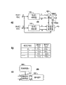
Fig. 3 a and c are the more detailed block diagrams of the various piece of transmission system shown in Figure 1, and also comprise a Gray code mapper, and Fig. 3 b is the tables of data that comprises the operation of control Gray code mapper.
Fig. 4 is the more detailed block diagram of the part of the transmission system that exemplifies among Fig. 1, has exemplified the operation of the different Error detection/correcting codes that are used for different stage.
Fig. 5 is the planisphere that receives, and Fig. 6 is the figure of a quadrant that is transmitted the reception constellation of distortion that channel causes.
Fig. 7 is the block diagram of circuit of center of gravity that is used for the quadrant of the constellation data point that determine to receive.
Fig. 8 is a planisphere, has illustrated to use grouping factor to change the relevant bit-error level of different stage signal in the classification QAM signal.
Embodiment
Fig. 3 a and c are the more detailed block diagrams of the various piece of transmission system shown in Figure 1, and also comprise a Gray code mapper, and Fig. 3 b is the table that exemplifies the operation of the Gray code mapper that illustrates among Fig. 3 a and the c.At first with reference to figure 2b, exemplified the adjacent point of all positions wherein and represented the only planisphere of the different data value in bit position of its data value.For producing this constellation, the dibit group in rank 2 data-signals of coding for sub-quadrant in the map of position depend on sub-quadrant and be in which quadrant.Upper right hand quadrant (00) among Fig. 2 b is identical with upper right hand quadrant among Fig. 2 a.Yet, be listed as about in upper left hand quadrant and exchanged.Up-downgoing is exchanged in the hand quadrant of bottom right, and right-hand man's row and up-downgoing exchanged in the hand quadrant of lower-left.This can be by before the second data-signal DATA2 of modulating-coding, by the operation of the simple mapping in the transmitter 100, then by after second data-signal of the coding that is received is by demodulation, carries out in receiver 300 and simply separates map and operate and carry out.
In Fig. 3 a, the part of transmitter 100 has been described.Rank 1 code element (from two bits of first encoder 102 of Fig. 1) is connected respectively to a plurality of input terminals of rank 1 modulator 104 and Gray code mapper 112.Be connected to first input end of first adder 106 (I) and first input end that is connected to second adder 106 (Q) from quadrature (O) signal of rank 1 modulator 104 from homophase (I) signal of rank 1 modulator 104.The signal combiner that has been combined to form Fig. 1 106 of first adder 106 (I) and second adder 106 (Q).Rank 2 code elements (from two bits of second encoder 108) are connected to the input terminal of rank 2 modulators 110.The I lead-out terminal of rank 2 modulators 110 is connected to the I input terminal of Gray code mapper 112, the Q lead-out terminal of rank 2 modulators 110 is connected to the Q input terminal of Gray code mapper 112, the I lead-out terminal of Gray code mapper 112 is connected to second input terminal of first adder 106 (I), and the Q lead-out terminal of Gray code mapper 112 is connected to second input terminal of second adder 106 (Q).Be reduced graph, do not illustrate have a decay factor of 0.5 and be connected variable gain amplifier 111 between Gray code mapper 112 and the signal combiner 106.
In operation, rank 1 code element of being represented by the group of two coded data bits is received from rank 1 encoder 102 (Fig. 1).Rank 1 code element is carried out QPSK modulation by rank 1 modulator 104, produces the one group of I of quadrant of expression modulation signal and the signal of Q component in known manner.For example, if code element is 0, promptly dibit is 00, specify so upper right hand quadrant (I=1, Q=1); If code element is 1, promptly dibit is 01, specify so upper left hand quadrant (I=-1, Q=1); If code element is 2 to be that dibit is 10, specify so bottom right hand quadrant (I=1, Q=-1); If code element is 3 to be that dibit is 11, specify so lower-left hand quadrant (I=-1, Q=-1).In a similar manner, rank 2 code elements are carried out QPSK modulation by rank 2 modulators 110, produce the one group of I and the Q component signal of the sub-quadrant of expression modulation signal in known manner.Rank 2 modulators and rank 1 modulator 104 produce modulation signal in identical mode, if promptly dibit is 00 (0), specify so upper right hand quadrant (I=1, Q=1); If dibit is 01 (1), specify so upper left hand quadrant (I=-1, Q=1); If dibit is 10 (2), specify so bottom right hand quadrant (I=1, Q=-1); If dibit is 11 (3), specify so lower-left hand quadrant (I=-1, Q=-1).The signal of this modulation is then by 0.5 weighting (not shown).
From the constellation that obtains of the combination of these two modulation signals shown in Fig. 2 a.Gray code mapper 112 operation from the I of rank 2 modulators 110 and Q signal to produce the planisphere shown in Fig. 2 b.Fig. 3 b is Gray code mapper 112 employed map lists.If rank 1 code element is 0, specify upper right hand quadrant, so sub-quadrant does not change, and promptly I and the Q output signal from rank 2 modulators do not change.Therefore, the I output signal is promptly from the Iout identical with I input signal Iin (Iout=Iin) of Gray code mapper 112, and the Q output signal is promptly from the Qout identical with Q input signal Qin (Qout=Qin) of Gray code mapper 112.If rank 1 code element is 1, specify upper left hand quadrant, so, with reference to figure 2, row are exchanged.It is negative to be that positive I value becomes, and vice versa.Therefore, when rank 1 code element was 1, the I output signal was the inverse value (Iout=-Iin) of I input signal, and the Q output signal is the inverse value (Qout=-Qin) of Q input signal simultaneously.If rank 1 code element is 2, specify bottom right hand quadrant, so, row is exchanged.It is negative to be that positive Q value becomes, and vice versa.Therefore, when rank 1 code element is 2, I output signal identical with the I input signal (Iout=Iin), the Q output signal is the inverse value (Qout=-Qin) of Q input signal simultaneously.If rank 1 code element is 3, specify lower-left hand quadrant, so, row and column is all exchanged, and promptly positive I value becomes negative, positive Q value and becomes negatively, and vice versa.Therefore, when rank 1 code element was 3, the I output signal was the inverse value (Iout=-Iin) of I input signal, and the Q output signal is the inverse value (Qout=-Qin) of Q input signal simultaneously.Gray code mapper 112 provides this function.I that obtains from Gray code mapper 112 and Q value are used 0.5 weighted value weighting (not shown for simplifying) as mentioned above and are represented that by signal combiner 106 usefulness the I of rank 1 code element and Q value make up.The planisphere of gained is shown among Fig. 2 b.
Such map is reversible in the receiver 300 that uses similar Gray code mapper.Fig. 3 cs shows the part of the receiver 300 that comprises such Gray code mapper 314.In Fig. 3 c, the lead-out terminal of encoder 308 is connected to the input terminal of Gray code mapper 314 again.Be connected to the I input terminal of Gray code mapper 314 from the I signal of subtracter 310 (Fig. 1), and the Q signal of subtracter 310 is connected to the Q input terminal of Gray code mapper 314.The I lead-out terminal of Gray code mapper 314 is connected to the I input terminal of second decoder 312, and the Q lead-out terminal of Gray code mapper 314 is connected to the Q input terminal of second decoder 312.
In operation, encoder 308 produces the signal of the desirable rank that expression received 1 code element again.That is, be any position that is in the upper right hand quadrant if rank 1 signal that receives is determined, encoder 308 generation values are 0 signal so again; If any position in upper left hand quadrant, then generation value is 1 signal; If any position in the hand quadrant of bottom right, then generation value is 2 signal; If any position in the hand quadrant of lower-left, then generation value is 3 signal.This code element is provided for Gray code mapper 314.I and Q signal from subtracter 310 are handled in the mode that exemplifies among above-mentioned and Fig. 3 b by Gray code mapper 314 respectively, those skilled in the art will understand that the Gray code mapper 314 in the receiver 300 operates in an identical manner with the Gray code mapper 112 among Fig. 3 a, and will carry out reverse functions performed in transmitter 100.
In transmitter 100 and receiver 300, use Gray code mapper (112 and 312) to allow the aforesaid way relevant to use the planisphere that exemplifies among Fig. 2 b with Fig. 3 a.Use the transmission system of above-mentioned Gray code map function, adjacent for producing, only be no more than a constellation that bit is different, will increase the error rate of system.Anti-very having illustrated uses aforesaid Gray code that rank 2 bit error code numbers are reduced half.This provides the additional allowance of about 1/4dB in signal noise ratio (SNR).Improve the performance of having improved transmission system generally though this improvement is not very big with other.
Fig. 4 is the more detailed block diagram of the part of the transmission system shown in Fig. 1, and it has exemplified the operation of the different Error detection/correcting codes of different stage.As mentioned above, because the compression of the distance between the constellation point in the modulation of higher level that applied non-linear high power amplifier brought in the broadcasting-satellite system, the different stage of QPSK modulation is subjected to deterioration in various degree.More clearly, than low level the bit mistake appears more continually the high-level of hierarchical modulation.For closer mating the error rate of rank 1 and rank 2 signals, in each data flow, use Error detection/correcting code with different performance feature.More clearly, will be in high level data flow the stronger Error detection/correction coding of function of use, the more weak Error detection/correction coding of function of use in low-level data flow simultaneously.This will optimize the overall performance and the message transmission capacity of transmission system.
In Fig. 4, be denoted by like references with the identical parts that exemplify among Fig. 1, and no longer be described in detail hereinafter.In Fig. 4, first Error detection in the transmitter 100/correcting coder 102 is divided into an external encoder 102 (O) and an internal encoder 102 (I).Similarly, second Error detection/correcting coder 108 is divided into an external encoder 108 (O) and an internal encoder 108 (I).In the corresponding way, first Error detection in the receiver 300/correction decoder device 304 is divided into an outer decoder 304 (O) and an inner decoder 304 (I).Similarly, second Error detection/correction decoder device 312 is divided into an outer decoder 312 (O) and an inner decoder 312 (I).As announcing in above-mentioned patent document, external encoder/decoder is to adopting the block encoding technique as Hamming code, Hadamard codes, cyclic code and Reed-Solomon (RS) sign indicating number, and internal encoder/decoder is to adopting convolution code simultaneously.
In Fig. 4, it is much better than that the encoding ratio that is used for rank 2 data flow is used for the encoding function of rank 1 data flow.More clearly, it is more much better than than the convolution code function of the internal encoder that is used in rank 1 data flow/decoder centering to be used in the convolution code of internal encoder/decoder centering of rank 2 data flow.For example, in a preferred embodiment, handle the first internal encoder/decoder of rank 1 data flow the convolution code that adopts speed 1/2 constraint length 7 is deleted by 7/8 speed.Second internal encoder/decoder of handling rank 2 data flow adopts the nothing of speed 1/2 constraint length 7 to delete and cuts convolution code.The encoding function of encoding ratio rank 1 data flow of rank 2 data flow is stronger.This closer mates the error rate level of rank 1 and rank 2 data flow, and has optimized the performance of transmission system on the whole.
As mentioned above and exemplify among Fig. 1, rank 1 demodulator 302 and decoder 304 are used to detect the DATA1 signal from the constellation that receives jointly.Deducted from the constellation that is received from the reconstruct ideal signal of this detected DATA1 signal of expression of encoder 308 more then, and the conversion that causes the constellation that received ideally is to form another constellation that detects the sub-quadrant in the quadrant.Yet, this conversion operations be the reality " central point " of the quadrant that received very easily and again the desired center point of encoder 308 hypothesis (from the initial point of rank 1 constellation depart from ± 1) between any unmatched influence.The virtual center point that not the matching of any size between constellation that is received and both ideal constellation causes receiving quadrant departs from the central point of hypothesis, and when encoder 308 and subtracter 310 are changed the constellation that is received again, cause the virtual center point of polaron quadrant to depart from the initial point that second decoder 312 is supposed.Therefore, for the central point with sub-quadrant is placed on correct position (initial point) accurately to be decoded by second decoder 312, must correctly allocate the gain of receive channel.
In known transmission system, the gain of system is determined by the data point constellation of relatively reception and known ideal strong point constellation.Yet, and several problems are arranged so that the accurate maintenance of this gain is relevant.At first, in some transmission systems, the position of constellation point is perhaps by the ideal position that intentionally departs from them.Resulting constellation is the equally spaced point as exemplifying among Fig. 2 not.The second, transmission channel is not constant, and perhaps the variable nonlinear noise of total amount is arranged.For the position of the central point of determining quadrant and the gain of system, in such system, determine the center of gravity of all data points in the quadrant.
Fig. 7 is the block diagram of circuit of center of gravity that is used to determine the quadrant of the data point constellation that received.In Fig. 7, circulator 321 receives expression from the I of the continuous reception data point of rank 1 demodulator 302 (Fig. 1) and the I and the Q value of Q component.The I lead-out terminal of circulator 321 is connected to the input terminal of I low pass filter (LPF) 320.The Q lead-out terminal of circulator 321 is connected to the input terminal of Q low pass filter 322.The lead-out terminal separately of I and Q LPFs 320 and 322 is connected to respective input of amplitude calculating circuit 324.The lead-out terminal of amplitude calculating circuit 324 is connected to encoder 308 again.
In the operation, circulator 321 rotates to the value that receives in the whichever quadrant upper right hand quadrant in known manner.Fig. 5 is planisphere that is received and the position that shows the modulating data point of a plurality of continuous receptions.This receives data point in all four quadrants, forms the point that looses near the position that the constellation point of each reception is supposed.Fig. 6 is the figure of the upper right hand quadrant of the constellation that received, and wherein all data points of constellation are rotated device 321 and rotate to this quadrant.The quadrant that exemplifies among Fig. 6 is represented to have the intentional predistortion of the constellation point that has been sent out and/or is operated the planisphere of the distortion that causes by transmission channel 200.
The sliding average of ordering with n from the I component of the data point that is rotated of circulator 321 has carried out low-pass filtering in LPF320.In the embodiment that exemplifies, this sliding average uses aforesaid 500 data point calculation.Q component from the data point that is rotated of circulator 321 has also been carried out low-pass filtering similarly with sliding average.One skilled in the art should appreciate that low pass filter 320,322 also can use iir digital filter separately to make up.Low-pass filtering operation produces I and the Q component that receives the center of gravity of data point in each quadrant.In amplitude calculating circuit 324, calculate the amplitude estimated value of center of gravity.For example, if r
i[n] is that filtered homophase I forms, and r
q[n] is filtered quadrature Q component, and the amplitude of center of gravity is calculated as so
Big or small desirable should be of the amplitude M of center of gravity
The amplitude M of the center of gravity of RESPONSE CALCULATION and adjusting from the amplitude of the desirable reconstruction signal of encoder 308 again.By correctly adjusting from the amplitude of the desirable reconstruction signal of encoder 308 again, the center of the quadrant of each reception will correctly be converted to initial point by subtracter 310, and allow being correctly decoded of rank 2 and higher level data-signal.
Whether the circuit that Fig. 7 exemplifies is with independent operation, linear or non-linear irrelevant with transmission method.When having predistortion transmission constellation or non-standard grouping factor, it also can proper operation (following will the detailed description in detail).Have been found that when being used for the classification 16QAM transmission system of process linear channel with original comparing about definite quadrant center, in fact this circuit works does not well have significantly deterioration.This circuit exist noise particularly as in direct satellite TV signal transmission system, find have the channel distortion that nonlinear channel brings the time, also operation is good.Such circuit has improved the performance of high-level data flow so has improved the overall performance of transmission system.
Again with reference to figure 1, in known classification QAM transmission system, the constellation that rank 2 modulators 110 produce in variable gain amplifier 111 by after the factor 0.5 weighting, the constellation combination that in signal combiner 106, produces with rank 1 modulator 104.This weighted factor 0.5 is called group factor and is the variable correlated performance with change rank 1 and rank 2 data flow, as will be described in detail.With reference to figure 2a, the constellation of gained is made up of equally spaced constellation point.As mentioned above, such arrangement has caused in this transmission system, and the performance about the error rate of rank 1 data flow is better than rank 2 data flow.By changing this grouping factor, the correlated performance of rank 1 and rank 2 data flow can be more near coupling.
With reference to figure 8a, the gain of variable amplifier (Fig. 1 111) is adjusted to 0.3.The constellation point of gained and the central point of quadrant be spacing 0.3 only.Person of skill in the art will appreciate that the constellation that exemplifies among the constellation that exemplifies in Fig. 8 a and Fig. 2 a compares, the constellation point in the quadrant is farther apart from the constellation point of other quadrant.On the contrary, the constellation point in the quadrant is than more closely getting together of exemplifying among Fig. 2 a.Such system allows correctly to determine the quadrant at rank 1 data-signal place, cost is not really correctly to determine the constellation point of rank 2 data-signals in quadrant, therefore, compare, increased the performance of rank 1 data flow and weakened the performance of rank 2 data flow with the system of Fig. 2 a.
With reference to figure 8b, the gain of variable amplifier (Fig. 1 111) is adjusted to 0.7.The central point spacing 0.7 of constellation point and quadrant as a result.Person of skill in the art will appreciate that the constellation that exemplifies among the constellation that exemplifies in Fig. 8 b and Fig. 2 a compares, the constellation point in the quadrant is nearer apart from the constellation point of other quadrant.On the contrary, the constellation point in the quadrant is than separating further of exemplifying among Fig. 2 a.Such system allows more correctly to determine the constellation point of rank 2 data-signals in quadrant, cost is not really correctly to determine the quadrant at rank 1 data-signal place, therefore, compare, increased the performance of rank 2 data flow and weakened the performance of rank 1 data flow with the system of Fig. 2 a.
By the gain of variable gain amplifier 111 (Fig. 1) correctly is set, every group of constellation point can optimize placement in groups with more near the performance of coupling rank 1 and rank 2 data flow.Determined that for 16QAM transmission system grouping factor about 0.6 to 0.7 will be more near the performance of mating rank 1 and rank 2 data flow by non-linear direct satellite television channel transmission.This makes the as a whole overall performance that will increase transmission system.