CN100423982C - Riveted sprocket assembly - Google Patents
Riveted sprocket assembly Download PDFInfo
- Publication number
- CN100423982C CN100423982C CNB2005100752288A CN200510075228A CN100423982C CN 100423982 C CN100423982 C CN 100423982C CN B2005100752288 A CNB2005100752288 A CN B2005100752288A CN 200510075228 A CN200510075228 A CN 200510075228A CN 100423982 C CN100423982 C CN 100423982C
- Authority
- CN
- China
- Prior art keywords
- rivet
- load
- carrying element
- sprocket wheel
- sprocket
- Prior art date
- Legal status (The legal status is an assumption and is not a legal conclusion. Google has not performed a legal analysis and makes no representation as to the accuracy of the status listed.)
- Active
Links
Images


Classifications
-
- B—PERFORMING OPERATIONS; TRANSPORTING
- B62—LAND VEHICLES FOR TRAVELLING OTHERWISE THAN ON RAILS
- B62M—RIDER PROPULSION OF WHEELED VEHICLES OR SLEDGES; POWERED PROPULSION OF SLEDGES OR SINGLE-TRACK CYCLES; TRANSMISSIONS SPECIALLY ADAPTED FOR SUCH VEHICLES
- B62M9/00—Transmissions characterised by use of an endless chain, belt, or the like
- B62M9/04—Transmissions characterised by use of an endless chain, belt, or the like of changeable ratio
- B62M9/06—Transmissions characterised by use of an endless chain, belt, or the like of changeable ratio using a single chain, belt, or the like
- B62M9/10—Transmissions characterised by use of an endless chain, belt, or the like of changeable ratio using a single chain, belt, or the like involving different-sized wheels, e.g. rear sprocket chain wheels selectively engaged by the chain, belt, or the like
Landscapes
- Engineering & Computer Science (AREA)
- Chemical & Material Sciences (AREA)
- Combustion & Propulsion (AREA)
- Transportation (AREA)
- Mechanical Engineering (AREA)
- Gears, Cams (AREA)
Abstract
A riveted sprocket assembly that includes a sprocket carrier having a plurality of carrier arms and a plurality of sprockets attached to the carrier arms by rivets. First and second rivet heads of the rivets are countersunk into the carrier arms on one face and into the sprocket on the other face. The second rivet head is formed on the sprocket on the front face of the sprocket carrier. To prevent the riveting tool from damaging the sprocket during the riveting process, the rivet holes of the sprockets include a clearance portion around the second rivet head. This results in the sprocket having three-stepped rivet holes: a small diameter for the rivet shaft, an intermediate diameter for the rivet head and a larger diameter for the riveting tool. To minimize weight, the carrier arms narrow in a central region between radially inner and radially outer rivet holes on the carrier arms.
Description
Technical field
The present invention relates to bicycle chain wheel assembly, relate more specifically to comprise light-duty sprocket wheel load-carrying element and a plurality of chain wheel assembly with sprocket wheel of stepped appearance rivet hole, described rivet hole is configured to hold rivet stem, rivet head and rivet tool.
Background technology
Usually, the chain wheel assembly that is used to have the bicycle of gear transmission system comprises and is a plurality ofly supported with one heart and had a swedged gradually sprocket wheel by the sprocket wheel load-carrying element.For example, DE19937212A1 has disclosed a kind of chain wheel assembly, and it comprises a plurality of sprocket wheels that are installed on the stepped appearance four arm sprocket wheel load-carrying elements.Maximum sprocket wheel is supporting the sprocket wheel load-carrying element, and each step holds a sprocket wheel.Maximum sprocket wheel and sprocket wheel load-carrying element are nonrotatably mounted tO on the wheel hub, so that send the torque of other sprocket wheel to wheel hub.Other sprocket wheel is installed on sprocket wheel load-carrying element or the maximum sprocket wheel by rivet.
Disclosed another kind of chain wheel assembly in utility model DE 29623671U1, it comprises two chain wheel assemblies.Each sub-component comprises a hub and the load-carrying element arm that extends from this hub outward radial.Two sprocket wheels adopt identical rivet to be installed on each sub-component, and a sprocket wheel is installed on each surface of load-carrying element arm.Difference between the number of teeth on two sprocket wheels is less.Adopt distance piece to come dividually several other sprocket wheels to be installed on the cycle hub.
Thereby since wish to have a large amount of sprocket wheels cause gear ratio near and sprocket wheel external diameter difference is less and wish to have lightweight construction, so there are several shortcomings in top chain wheel assembly.A tight axial arranged shortcoming of each sprocket wheel on the sprocket wheel load-carrying element is the rivet head that stretches out, and it extend in the space between these sprocket wheels and with chain and interferes.The damage that sprocket surface caused of another problem in the riveted joint process, causing by rivet tool.Therefore, a plurality of sprocket wheels need be installed fine and are arranged on the sprocket wheel load-carrying element.
Summary of the invention
One object of the present invention is to provide a kind of chain wheel assembly, and this assembly is light-duty and stronger aspect antitorque, and is being preferable aspect the production of riveting operation and installation especially.The ladder-type structure of the lightweight construction of the arm by the sprocket wheel load-carrying element and the rivet hole by being used to hold rivet head on sprocket wheel is realized these purposes.
One object of the present invention is, avoids rivet head to exceed axial sprocket profiles by rivet head is imbedded, and avoids rivet tool that sprocket surface is caused damage by providing round the gap that the rivet head of rivet extends.
The invention provides a kind of riveted sprocket assembly that is used for bicycle, it comprises a sprocket wheel load-carrying element and a plurality ofly is installed in sprocket wheel on the load-carrying element by rivet.Rivet has a rivet stem and first and second rivet heads.Sprocket wheel comprises a plurality of rivet holes that are used to hold these rivets.The partial sum of immersing oneself in that these rivet holes comprise the hole portion that is used to hold rivet stem, be used to hold second rivet head is used to hold the gap portion of rivet tool.The hole portion of rivet hole has first diameter of the diameter of the rivet stem of being equal to or greater than.The part of immersing oneself in of rivet hole has second diameter that is equal to or greater than the rivet head diameter.Second diameter is greater than first diameter.The gap portion of rivet hole has the 3rd diameter that is configured to provide for rivet tool the gap.The 3rd diameter is equal to or greater than second diameter.
The sprocket wheel load-carrying element comprises a hub and a plurality of load-carrying element arm that extends from this hub outward radial.Described hub comprise a plurality of can with the spline with different in width of corresponding splined engagement on the wheel hub.The front surface of load-carrying element arm comprises the step that is used to hold sprocket wheel, and the rear surface of load-carrying element arm is essentially smooth.The load-carrying element arm also comprises the rivet hole that be used to receive rivet stem relevant with each step.In order to make the minimize weight of sprocket wheel load-carrying element, making the wall thickness of hub minimize and make the load-carrying element arm is level and smooth to the transition portion of hub.In addition, the circumferential width of load-carrying element arm is narrower at the middle section place, and broadens once more towards the radial outer end of load-carrying element arm.Although the load-carrying element arm has narrower middle section, because step has increased the radially inside axial width towards hub of load-carrying element arm, so the intensity of load-carrying element or stability can not be affected.The axial width of the end regions of load-carrying element arm is determined by the spacing of outside sprocket wheel.
Maximum and second largest sprocket wheel is installed on the rear surface and front surface of sprocket wheel load-carrying element in side direction respectively; Each load-carrying element arm adopts single rivet.Remaining sprocket wheel is installed on the front surface of load-carrying element arm.Because a large amount of sprocket wheels must be installed on the load-carrying element, so the axial space of sprocket wheel and the gap between adjacent sprocket wheel must minimize.
By rear surface at first rivet stem is inserted into the rivet hole of load-carrying element arm, thereby these sprocket wheels are installed on the load-carrying element from load-carrying element.Then, will be by rivet tool from the riveted joint of the extended rivet stem of the front surface of sprocket wheel and load-carrying element end, to form second rivet head.During riveting operation, rivet stem expands in the rivet hole of sprocket wheel, but is also contacting a part of rivet hole in the load-carrying element arm.It is motionless that this operation has guaranteed that rivet is locked in the rivet hole that is arranged on sprocket wheel and the load-carrying element arm, thereby cause sprocket wheel immovably seamlessly to be installed on the load-carrying element arm.
In another embodiment of the present invention, before installing, can adopt pin rivet rather than rivet that sprocket wheel is installed on the load-carrying element without any rivet head.After in the rivet hole that pin is inserted in sprocket wheel and load-carrying element arm, two ends by the rivet pin rivet form first and second rivet heads.During riveting operation, rivet stem becomes in the rivet hole that is locked in sprocket wheel and near the bore region the rivet hole of load-carrying element arm corresponding.
By this riveted sprocket assembly and by because its less number of teeth and the sprocket wheel that further reduces are not to be arranged on the sprocket wheel load-carrying element but to be arranged near this sprocket wheel load-carrying element, so can assemble out such chain wheel assembly, its have very little axial width and with compare lighter and more economical in those schemes described in the above-mentioned patent documentation.
By below in conjunction with the explanation of accompanying drawing, will understand these and other feature and advantage of the present invention more all sidedly to some embodiment of the present invention.
Description of drawings
In these accompanying drawings:
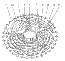
Fig. 1 is the front isometric view of chain wheel assembly according to an embodiment of the invention;
Fig. 2 is the stereo rearview of the chain wheel assembly of Fig. 1;
Fig. 3 is the front isometric view of sprocket wheel of the chain wheel assembly of Fig. 1;
Fig. 4 is the part sectional view of the chain wheel assembly of Fig. 1, has specifically illustrated to be used for sprocket wheel is installed in rivet on the sprocket wheel load-carrying element; With
Fig. 5 is the part sectional view of chain wheel assembly in accordance with another embodiment of the present invention.
Reference numerals list
1 chain wheel assembly
The 2a-2f sprocket wheel
3 sprocket wheel load-carrying elements
4 hubs
5 in-profiles
6 load-carrying element arms
7 rivets
8 steps
10 installation brackets
11 rivet holes immerse oneself in part
12 otch
13 rivet holes
The gap portion of 14 rivet holes
15 the 3rd diameters
16 first rivet heads
17 rivet stem
18 second rivet stem
19 pin rivets
Hole in 20 sprocket wheels
Tooth on 22 sprocket wheels
The rivet hole of 24 load-carrying element arms
The bar portion of 26 sprocket wheel rivet holes
30 first rivet heads
32 second rivet heads
The rivet stem of 34 pin rivets
36 first diameters
38 second diameters
40 load-carrying element arm rivet holes immerse oneself in part
The specific embodiment
Fig. 1-4 demonstrates riveted sprocket assembly 1 according to an embodiment of the invention.This chain wheel assembly 1 generally includes and a plurality ofly is installed in sprocket wheel 2a-2f on the sprocket wheel load-carrying element 3 by rivet 7, is six sprocket wheels in the present embodiment.This sprocket wheel load-carrying element 3 comprises hub 4 and a plurality of load-carrying element arm 6 that extends radially outwardly from this hub 4.Hub 4 comprise can with corresponding splined engagement on the wheel hub (not shown) so that transmit internal splines 5 torque, that have different in width effectively.In order to make the minimize weight of load-carrying element, hub 4 has bigger radius and 6 transition portion is level and smooth from hub 4 to arm.In addition, the wall thickness of hub 4 and the thickness of load-carrying element arm 6 are minimized.
Referring to Fig. 2, load-carrying element arm 6 comprises the step 8 that is used for holding sprocket wheel 2b-2e on the front surface that is arranged on sprocket wheel load-carrying element 3.Load-carrying element arm 6 is smooth basically on the rear surface of arm 6.In order to make minimize weight, the circumferential width of load-carrying element arm 6 is narrower in middle section, because the axial width of load-carrying element arm 6 increases towards hub 4 by the step 8 on the front surface of load-carrying element arm 6, so this can not reduce the intensity or the stability of load-carrying element arm 6.The axial width of the end regions of load-carrying element arm 6 is by externally the spacing between the sprocket wheel is definite.Load-carrying element arm 6 also comprises the rivet hole 24 that is used to hold rivet 7, and five rivet holes are arranged on each load-carrying element arm 6 in the present embodiment.These rivets 7 comprise a rivet stem 17 and first rivet head 16.The rivet stem 17 of rivet 7 is inserted into the rivet hole 24 from the rear surface of load-carrying element arm 6, and is riveted on the front surface of sprocket wheel 2 to form second rivet head 18.Maximum sprocket wheel 2f and second largest sprocket wheel 2e are installed on each load-carrying element arm 6 by a rivet 7.Maximum sprocket wheel 2f is installed on the rear surface of load-carrying element arm 6, and second largest sprocket wheel 2e is installed on the front surface of load-carrying element arm 6.
Referring to Fig. 3, sprocket wheel 2a-2f comprises a plurality of installation brackets that extend radially inwardly 10, is five installation brackets in this embodiment.In order to make minimize weight, be used to improve chain the tooth of the cross sections 12 that switches between the sprocket wheel 2a-2f except comprising, sprocket wheel 2a-2f also comprises the hole 20 that is positioned under each tooth 22.In order to make minimize weight, make towards hub diameter to minimize equally to the sprocket wheel quantity of material that extends internally.Rivet hole 13 is arranged on the installation bracket 10.These rivet holes 13 comprise the shank 17 that is used to hold rivet 7 hole portion 26, be used to hold second rivet head 18 immerse oneself in part 11 and be used to hold the gap portion 14 of rivet tool (not shown).The hole portion 26 in hole 13 has first diameter 36 of the diameter of the shank 17 that do not expand that is equal to or greater than rivet 7.The part 11 of immersing oneself in hole 13 has second diameter 38 of the diameter that is equal to or greater than second rivet head 18.The gap portion 14 in hole 13 has the 3rd diameter 15 that is configured for providing for rivet tool the gap, and its diameter is greater than the end of rivet tool.Second diameter 38 is greater than first diameter 36.The 3rd diameter 15 is greater than second diameter 38.Perhaps, immersing oneself in second diameter partly can be the same big with the 3rd diameter of gap portion, but this can damage the intensity of sprocket wheel, and this sprocket wheel has had very open structure in the zone of second rivet head.
Fig. 4 demonstrates three maximum sprocket wheel 2d-2f that are riveted on one of them load-carrying element arm 6.Adopt single rivet 7 that maximum sprocket wheel 2f is installed on the rear surface of load-carrying element arm 6, and second largest sprocket wheel 2e is installed on the front surface of load-carrying element arm 6.The third-largest sprocket wheel 2e and other sprocket wheel 2b-2d are riveted on respectively on the end face of step 8 of load-carrying element arm 6.Sprocket wheel 2a is riveted on the front surface of load-carrying element arm 6.For sprocket wheel 2 is installed on the load-carrying element arm 6, the rivet stem 17 of rivet 7 is inserted into the rivet hole 24 from the rear surface of load-carrying element arm 6.What first rivet head, 16 parts were embedded to rivet hole 24 on the rear surface that is arranged in load-carrying element arm 6 immerses oneself in part 40, thereby causes having only sub-fraction rivet head 16 to extend beyond the flat surfaces basically of the rear surface of load-carrying element arm 6.On the end of the rivet stem 17 of the front surface that extends through load-carrying element arm 6, form second rivet head 18 by rivet tool.During riveting operation, rivet stem 17 expands and presses rivet hole 13 in the sprocket wheel 2, and presses a part of rivet hole 24 that is arranged in load-carrying element arm 6.This is not only between rivet 7 and the sprocket wheel 2 but also formed reliable connection between the load-carrying element arm 6 of rivet 7 and sprocket wheel load-carrying element 3.Sprocket wheel 2 movably and is not installed on the sprocket wheel load-carrying element 3 with aiming at as a result.Second rivet head, 18 parts are contained in immersing oneself in the part 11 of rivet hole 13, and can not extend beyond the front surface of sprocket wheel load-carrying element 3.The gap portion 14 of rivet hole 13 has prevented that rivet tool from directly clashing into sprocket wheel 2 during riveting operation.
Fig. 5 demonstrates another embodiment of the present invention, and the embodiment of it and Fig. 1-4 is similar, except having replaced rivet 7 with pin rivet 19.Be formed on first rivet head 30 on the rear surface of sprocket wheel load-carrying element 3 and second rivet head 32 on the front surface of sprocket wheel load-carrying element 3 with rivet tool.During riveting operation, the rivet stem 34 of pin rivet 19 expands, and press the rivet hole 13 that is arranged in sprocket wheel 2 and press a part of rivet hole 24 of load-carrying element arm 6, thereby not only between rivet 19 and sprocket wheel 2e and 2f but also between rivet 19 and load-carrying element arm 6, formed reliable the connection.Second largest sprocket wheel 2e of result and maximum sprocket wheel 2f movably and are not installed on the sprocket wheel load-carrying element 3 with aiming at.Second rivet head, 32 parts are contained in immersing oneself in the part 11 of sprocket wheel 2, and can not extend beyond the front surface of sprocket wheel 2.This gap 14 has prevented that rivet tool from directly clashing into sprocket wheel 2 during riveting operation.
As shown in these accompanying drawings, prevent that by the gap around rivet head rivet tool from causing damage to sprocket wheel; And the open architecture by sprocket wheel, thin hub wall thickness and make the narrower minimize weight that makes chain wheel assembly of load-carrying element arm.
Though with reference to several embodiment describe the present invention, it being understood that under the situation of the spirit and scope that do not break away from described inventive concept and can make many variations.Therefore, the invention is not restricted to these disclosed embodiment, it can comprise the four corner that language limited by following claim.
Claims (7)
1. a riveted sprocket assembly (1), this assembly is used for bicycle, and it comprises:
One sprocket wheel load-carrying element (3), it has a plurality of load-carrying element arms (6);
A plurality of sprocket wheels (2a-2f), they have a plurality of rivet holes (13); And
A plurality of rivets (7) are used for sprocket wheel (2a-2f) is installed in load-carrying element arm (6), and these rivets (7) have a shank (17) and first and second rivet heads (16,18,30,32), second rivet head (18,32) is on the surface that is formed on sprocket wheel (2a-2f) during the riveting operation
The rivet hole of these sprocket wheels (13) has the hole portion (26) of the shank (17) that is used to hold rivet (7),
It is characterized in that described rivet hole (13) also has the gap portion (14) of immersing oneself in part (11) and being used to hold rivet tool at second rivet head (18) on every side that is used to hold second rivet head (18).
2. riveted sprocket assembly as claimed in claim 1, it is characterized in that, the described hole portion (26) of described rivet hole (13) has first diameter (36) of the diameter of the shank (17) that equals described rivet (7) at least, the part (11) of immersing oneself in of described rivet hole (13) has second diameter (38) of the diameter that equals second rivet head (18) at least, described gap portion (14) has the 3rd diameter (15) that is configured to provide for rivet tool the gap, described second diameter (38) is greater than first diameter (36), and the 3rd diameter (15) equals second diameter (38) at least.
3. riveted sprocket assembly as claimed in claim 2, it is characterized in that, described load-carrying element arm (6) comprises a plurality of rivet holes (24), described rivet stem (17) constitutes expanding at least a portion rivet hole (24) of the rivet hole (13) of sprocket wheel and load-carrying element arm (6) during the riveting operation, up to rivet stem (17) is fixed in sprocket wheel (2) and the load-carrying element arm (6).
4. riveted sprocket assembly as claimed in claim 1, it is characterized in that, described rivet (7) constitutes in the rivet hole (24) that at first is inserted into load-carrying element arm (6), be inserted into the rivet hole (13) that is arranged on the sprocket wheel (2) then, the rivet hole (24) of described load-carrying element arm (6) has immerse oneself in partly (40) that are used for holding described first rivet head (16).
5. riveted sprocket assembly as claimed in claim 4, it is characterized in that, the described rivet hole (24) of described load-carrying element arm (6) immerse oneself in the diameter of part (40) greater than the diameter of described first rivet head (16), and first rivet head (16) of immersing oneself in flushes basically with the surface of load-carrying element arm (6).
6. riveted sprocket assembly as claimed in claim 2, it is characterized in that, maximum sprocket wheel (2f) in described a plurality of sprocket wheel is installed on the rear surface of load-carrying element arm (6), and second largest sprocket wheel (2e) is installed on the front surface of load-carrying element arm (6) maximum and second largest sprocket wheel (2e; 2f) be riveted on each load-carrying element arm (6) by a rivet (7).
7. riveted sprocket assembly as claimed in claim 6, it is characterized in that, during riveting operation, described first and second rivet heads (30,32) both is formed on the respective end place of rivet (19), and rivet stem (34) is expanding near first rivet head (30) zone and near second rivet head (32) zone in the rivet hole of second largest sprocket wheel (2e), maximum sprocket wheel (2f) and load-carrying element arm (6).
Applications Claiming Priority (2)
| Application Number | Priority Date | Filing Date | Title |
|---|---|---|---|
| DE102004027963.2 | 2004-06-08 | ||
| DE102004027963.2A DE102004027963B4 (en) | 2004-06-08 | 2004-06-08 | Riveted sprocket set |
Publications (2)
| Publication Number | Publication Date |
|---|---|
| CN1706714A CN1706714A (en) | 2005-12-14 |
| CN100423982C true CN100423982C (en) | 2008-10-08 |
Family
ID=34937205
Family Applications (1)
| Application Number | Title | Priority Date | Filing Date |
|---|---|---|---|
| CNB2005100752288A Active CN100423982C (en) | 2004-06-08 | 2005-06-07 | Riveted sprocket assembly |
Country Status (4)
| Country | Link |
|---|---|
| US (1) | US8100795B2 (en) |
| EP (1) | EP1604894B1 (en) |
| CN (1) | CN100423982C (en) |
| DE (2) | DE102004027963B4 (en) |
Families Citing this family (50)
| Publication number | Priority date | Publication date | Assignee | Title |
|---|---|---|---|---|
| US20080004143A1 (en) * | 2006-06-16 | 2008-01-03 | Shimano Inc. | Bicycle sprocket assembly |
| US7854673B2 (en) * | 2006-08-31 | 2010-12-21 | Shimano Inc. | Bicycle sprocket assembly having a reinforcement member coupled between sprockets |
| JP2008189254A (en) | 2007-02-07 | 2008-08-21 | Shimano Inc | Rear sprocket assembly for bicycle, and sprocket |
| ITMI20071660A1 (en) | 2007-08-09 | 2009-02-10 | Campagnolo Srl | MOTION BIKE TRANSMISSION SYSTEM |
| ITMI20071661A1 (en) * | 2007-08-09 | 2009-02-10 | Campagnolo Srl | ASSEEME OF WHEELS TOOTHED FOR A BICYCLE |
| US9211583B2 (en) | 2008-09-26 | 2015-12-15 | Borgwarner Inc. | Sleeved sprocket teeth |
| DE102010027228B4 (en) | 2009-11-04 | 2021-12-09 | Sram Deutschland Gmbh | Multiple sprocket arrangement for bicycles |
| US8574108B2 (en) * | 2010-06-21 | 2013-11-05 | Vpower Racing USA, Inc. | Sprockets made of two materials with half holes on the edge of central portion |
| CN102476695A (en) * | 2010-11-30 | 2012-05-30 | 天心工业股份有限公司 | Bicycle chain wheel |
| US8663044B2 (en) * | 2011-03-21 | 2014-03-04 | De-Hsin Lin | Sprocket assembly that is worked easily and quickly |
| US8968130B2 (en) | 2011-03-23 | 2015-03-03 | Tien Hsin Industries Co., Ltd. | Bicycle cogset with support element |
| DE102011103489A1 (en) * | 2011-06-03 | 2012-12-06 | Sram Deutschland Gmbh | Multiple sprocket assembly for a bicycle transmission and rear wheel axle assembly with such a multiple sprocket assembly |
| TWI701186B (en) * | 2011-07-13 | 2020-08-11 | 德商矢倫德國股份有限公司 | Transmission seat device with small sprocket and multi-sprocket configuration for bicycle transmission |
| US9533735B2 (en) * | 2013-07-19 | 2017-01-03 | Sram Deutschland Gmbh | Multiple-sprocket arrangement for a bicycle gearing |
| US9415835B2 (en) * | 2014-01-24 | 2016-08-16 | Shimano Inc. | Rotatable annular bicycle component and bicycle rear sprocket |
| US9394986B2 (en) | 2014-02-10 | 2016-07-19 | Wolf Tooth Components, LLC | Sprocket |
| US9581229B2 (en) | 2014-02-10 | 2017-02-28 | Wolf Tooth Components, LLC | Sprocket |
| US9394987B2 (en) | 2014-02-10 | 2016-07-19 | Wolf Tooth Components, LLC | Sprocket |
| US9581230B2 (en) | 2014-02-10 | 2017-02-28 | Wolf Tooth Components, LLC | Sprocket |
| US11041558B2 (en) * | 2014-03-14 | 2021-06-22 | ZPE Licensing Inc. | Super charger components |
| US9581231B2 (en) | 2014-04-08 | 2017-02-28 | Wolf Tooth Components, LLC | Sprocket |
| US9625027B2 (en) | 2014-04-08 | 2017-04-18 | Wolf Tooth Components, LLC | Sprocket |
| US9404565B2 (en) | 2014-04-08 | 2016-08-02 | Wolf Tooth Components, LLC | Sprocket |
| US9463844B2 (en) * | 2014-09-01 | 2016-10-11 | Shimano Inc. | Bicycle sprocket and bicycle sprocket assembly |
| US9334014B2 (en) * | 2014-09-01 | 2016-05-10 | Shimano Inc. | Bicycle sprocket and bicycle sprocket assembly |
| DE102015203709A1 (en) * | 2015-03-02 | 2016-09-08 | Sram Deutschland Gmbh | Pinion arrangement with adapter |
| US20160272002A1 (en) | 2015-03-17 | 2016-09-22 | Praxis Works LLC | Cassette and bicycle wheel assembly |
| US9168976B1 (en) * | 2015-03-17 | 2015-10-27 | Praxis Works LLC | Cassette and bicycle wheel assembly |
| DE102015205736B4 (en) * | 2015-03-30 | 2024-05-16 | Sram Deutschland Gmbh | Bicycle rear wheel sprocket arrangement |
| US9511819B1 (en) * | 2015-05-25 | 2016-12-06 | Shimano Inc. | Bicycle rear sprocket assembly |
| US10703441B2 (en) * | 2015-07-03 | 2020-07-07 | Sram Deutschland Gmbh | Drive arrangement for a bicycle |
| US10407126B2 (en) * | 2015-08-28 | 2019-09-10 | Shimano Inc. | Bicycle rear sprocket assembly and bicycle rear sprocket |
| US10377445B2 (en) * | 2016-09-20 | 2019-08-13 | Shimano Inc. | Bicycle front sprocket assembly |
| IT201700015311A1 (en) * | 2017-02-13 | 2018-08-13 | Campagnolo Srl | Set of sprockets for sprocket set |
| US10618597B2 (en) * | 2017-02-17 | 2020-04-14 | Shimano Inc. | Bicycle sprocket assembly |
| US10442496B2 (en) * | 2017-03-29 | 2019-10-15 | Shimano Inc. | Bicycle sprocket assembly |
| US10773772B2 (en) * | 2017-04-12 | 2020-09-15 | Shimano Inc. | Bicycle sprocket assembly |
| US10889353B2 (en) * | 2018-01-24 | 2021-01-12 | Shimano Inc. | Bicycle rear sprocket assembly |
| US10717495B2 (en) * | 2017-09-15 | 2020-07-21 | Shimano Inc. | Bicycle sprocket |
| US10926836B2 (en) * | 2017-08-24 | 2021-02-23 | Shimano Inc. | Bicycle rear sprocket assembly |
| US10668980B2 (en) * | 2017-08-24 | 2020-06-02 | Shimano Inc. | Bicycle rear sprocket assembly |
| DE102017008074A1 (en) * | 2017-08-28 | 2019-02-28 | Sram Deutschland Gmbh | Sprocket carrier and multiple sprocket assembly |
| IT201700107554A1 (en) * | 2017-09-26 | 2019-03-26 | Campagnolo Srl | Sprocket assembly component for bicycle and bike drive transmission system |
| IT201700115411A1 (en) * | 2017-10-13 | 2019-04-13 | Campagnolo Srl | Bodice for a rear wheel hub of a bicycle and sprocket set suitable for being mounted on the hub by means of this body |
| IT201700115407A1 (en) | 2017-10-13 | 2019-04-13 | Campagnolo Srl | Sprocket and bodice for mounting on a bicycle rear wheel hub |
| US10864964B2 (en) * | 2018-08-31 | 2020-12-15 | Shimano Inc. | Bicycle sprocket assembly |
| US11008065B2 (en) * | 2018-11-07 | 2021-05-18 | Shimano Inc. | Bicycle sprocket arrangement |
| DE102019202529A1 (en) * | 2019-02-25 | 2020-08-27 | Shimano, Inc. | Bicycle sprocket assembly |
| US11529827B2 (en) * | 2020-12-10 | 2022-12-20 | Tien Hsin Industries Co., Ltd. | Transmission assembly of a bicycle |
| USD1040033S1 (en) * | 2022-11-16 | 2024-08-27 | Sram Deutschland Gmbh | Bicycle sprocket assembly |
Citations (3)
| Publication number | Priority date | Publication date | Assignee | Title |
|---|---|---|---|---|
| CN1186752A (en) * | 1996-12-20 | 1998-07-08 | 株式会社岛野 | Multiple sprocket assembly for bicycle |
| DE29623671U1 (en) * | 1995-09-29 | 1999-03-18 | Shimano Inc., Sakai, Osaka | Sprocket assembly for a bicycle |
| DE19937212A1 (en) * | 1999-08-06 | 2001-02-15 | Sram De Gmbh | Sprocket cassette for a derailleur system of a bicycle |
Family Cites Families (12)
| Publication number | Priority date | Publication date | Assignee | Title |
|---|---|---|---|---|
| JPH04297390A (en) * | 1991-03-27 | 1992-10-21 | Shimano Inc | Multistage wheel for bicycle rear wheel |
| US5213550A (en) * | 1992-01-23 | 1993-05-25 | Wu Chuen Fwu | Variable speed-type bicycle chain ring assembly |
| US5314366A (en) * | 1993-03-25 | 1994-05-24 | Palm Kirby A | Adapter chainring |
| JP3562883B2 (en) | 1995-09-29 | 2004-09-08 | 株式会社シマノ | Multi-stage wheels for bicycle rear wheels |
| JP3578541B2 (en) * | 1996-02-20 | 2004-10-20 | 株式会社エクセディ | Viscous damper mechanism |
| US6428437B1 (en) * | 1999-06-10 | 2002-08-06 | Raphael Schlanger | Power transmission assembly |
| US6382381B1 (en) * | 2000-09-06 | 2002-05-07 | Shimano Inc. | Bicycle hub assembly |
| US20030073531A1 (en) * | 2001-10-15 | 2003-04-17 | Apex Bicycle Components Corporation Ltd. | Combination of sprocket set and rivet structure |
| US20030153423A1 (en) * | 2002-02-14 | 2003-08-14 | Smith Garrett Andrew | Bicycle chainring fastener system |
| CZ295029B6 (en) * | 2002-08-26 | 2005-05-18 | Supersprox, A.S. | Lightweight sprocket |
| EP1407962A1 (en) * | 2002-10-11 | 2004-04-14 | Campagnolo Srl | Sprocket support member for a bicycle sprocket assembly |
| DE10260565B4 (en) * | 2002-12-21 | 2016-09-15 | Sram Deutschland Gmbh | The sprocket assembly |
-
2004
- 2004-06-08 DE DE102004027963.2A patent/DE102004027963B4/en not_active Expired - Fee Related
-
2005
- 2005-05-31 US US10/908,892 patent/US8100795B2/en not_active Expired - Fee Related
- 2005-06-03 DE DE602005011893T patent/DE602005011893D1/en active Active
- 2005-06-03 EP EP05011982A patent/EP1604894B1/en active Active
- 2005-06-07 CN CNB2005100752288A patent/CN100423982C/en active Active
Patent Citations (3)
| Publication number | Priority date | Publication date | Assignee | Title |
|---|---|---|---|---|
| DE29623671U1 (en) * | 1995-09-29 | 1999-03-18 | Shimano Inc., Sakai, Osaka | Sprocket assembly for a bicycle |
| CN1186752A (en) * | 1996-12-20 | 1998-07-08 | 株式会社岛野 | Multiple sprocket assembly for bicycle |
| DE19937212A1 (en) * | 1999-08-06 | 2001-02-15 | Sram De Gmbh | Sprocket cassette for a derailleur system of a bicycle |
Also Published As
| Publication number | Publication date |
|---|---|
| EP1604894B1 (en) | 2008-12-24 |
| DE102004027963B4 (en) | 2015-12-24 |
| DE102004027963A1 (en) | 2005-12-29 |
| US20050272546A1 (en) | 2005-12-08 |
| EP1604894A2 (en) | 2005-12-14 |
| DE602005011893D1 (en) | 2009-02-05 |
| CN1706714A (en) | 2005-12-14 |
| EP1604894A3 (en) | 2007-10-24 |
| US8100795B2 (en) | 2012-01-24 |
Similar Documents
| Publication | Publication Date | Title |
|---|---|---|
| CN100423982C (en) | Riveted sprocket assembly | |
| US10328995B2 (en) | Multi-sprocket arrangement for a bicycle | |
| US10730585B2 (en) | Multiple sprocket assembly for a bicycle | |
| US8371660B2 (en) | Load transmitting insert for a soft spline body | |
| US8911314B2 (en) | Multiple sprocket assembly | |
| US9260158B2 (en) | Multi-gear cassette for a bicycle | |
| CN107380340B (en) | Bicycle front chain wheel | |
| US6102821A (en) | Multiple sprocket assembly for a bicycle | |
| US7442140B2 (en) | Gear assembly for a bicycle gear change | |
| EP1972541B1 (en) | Bicycle multi-gear cassette | |
| US9150280B2 (en) | Bicycle multi-gear cassette | |
| EP2554468A1 (en) | Bicycle sprocket assembly | |
| US20110127746A1 (en) | Lightweight heavy duty bushing with easy assembly | |
| US10889353B2 (en) | Bicycle rear sprocket assembly | |
| CN109421887A (en) | Sprocket carrier and multichain wheel apparatus | |
| US20080230344A1 (en) | Bicycle Multi-Gear Cassette | |
| CN205769959U (en) | Bicycle gear sprocket wheel | |
| CN110799406A (en) | Steering shaft for a motor vehicle and method for producing the same | |
| CN205047643U (en) | Eccentric shaft | |
| EP0197536B1 (en) | Improvements in or relating to bicycle sprocket drive assemblies | |
| TWI270619B (en) | Riveted sprocket assembly | |
| WO2008155172A3 (en) | Shaft-hub connection, particularly of a selector fork unit, and method for the production of a shaft-hub connection of said kind | |
| CN211343879U (en) | Heavy-load cranked link chain | |
| CN216589605U (en) | Interface structure of bimetal shaft sleeve | |
| CN213628769U (en) | Chain transmission special-shaped tooth chain wheel |
Legal Events
| Date | Code | Title | Description |
|---|---|---|---|
| C06 | Publication | ||
| PB01 | Publication | ||
| C10 | Entry into substantive examination | ||
| SE01 | Entry into force of request for substantive examination | ||
| C14 | Grant of patent or utility model | ||
| GR01 | Patent grant |