CN100423944C - Ink jet printer - Google Patents
Ink jet printer Download PDFInfo
- Publication number
- CN100423944C CN100423944C CNB2005100527519A CN200510052751A CN100423944C CN 100423944 C CN100423944 C CN 100423944C CN B2005100527519 A CNB2005100527519 A CN B2005100527519A CN 200510052751 A CN200510052751 A CN 200510052751A CN 100423944 C CN100423944 C CN 100423944C
- Authority
- CN
- China
- Prior art keywords
- balladeur train
- ink
- bubble
- switching member
- exhaust
- Prior art date
- Legal status (The legal status is an assumption and is not a legal conclusion. Google has not performed a legal analysis and makes no representation as to the accuracy of the status listed.)
- Expired - Fee Related
Links
- 239000000976 ink Substances 0.000 claims description 100
- 230000033001 locomotion Effects 0.000 claims description 73
- 238000012423 maintenance Methods 0.000 claims description 48
- 238000007599 discharging Methods 0.000 claims description 13
- 230000015572 biosynthetic process Effects 0.000 claims description 8
- 229920002379 silicone rubber Polymers 0.000 claims description 7
- 238000000034 method Methods 0.000 description 14
- 230000008569 process Effects 0.000 description 12
- 230000000694 effects Effects 0.000 description 10
- 230000007246 mechanism Effects 0.000 description 8
- 230000001360 synchronised effect Effects 0.000 description 6
- 230000000903 blocking effect Effects 0.000 description 5
- 229920001971 elastomer Polymers 0.000 description 4
- 230000008531 maintenance mechanism Effects 0.000 description 4
- 230000005499 meniscus Effects 0.000 description 4
- 238000010992 reflux Methods 0.000 description 4
- 230000000740 bleeding effect Effects 0.000 description 3
- 230000002093 peripheral effect Effects 0.000 description 3
- 230000005540 biological transmission Effects 0.000 description 2
- 230000008859 change Effects 0.000 description 2
- 238000005516 engineering process Methods 0.000 description 2
- 239000000463 material Substances 0.000 description 2
- 230000009467 reduction Effects 0.000 description 2
- 238000007789 sealing Methods 0.000 description 2
- 239000002699 waste material Substances 0.000 description 2
- 238000005452 bending Methods 0.000 description 1
- 239000003086 colorant Substances 0.000 description 1
- 230000006835 compression Effects 0.000 description 1
- 238000007906 compression Methods 0.000 description 1
- 125000004122 cyclic group Chemical class 0.000 description 1
- 230000008030 elimination Effects 0.000 description 1
- 238000003379 elimination reaction Methods 0.000 description 1
- 238000011010 flushing procedure Methods 0.000 description 1
- 230000008676 import Effects 0.000 description 1
- 239000000049 pigment Substances 0.000 description 1
- 229920003002 synthetic resin Polymers 0.000 description 1
- 239000000057 synthetic resin Substances 0.000 description 1
Images


Classifications
-
- B—PERFORMING OPERATIONS; TRANSPORTING
- B41—PRINTING; LINING MACHINES; TYPEWRITERS; STAMPS
- B41J—TYPEWRITERS; SELECTIVE PRINTING MECHANISMS, i.e. MECHANISMS PRINTING OTHERWISE THAN FROM A FORME; CORRECTION OF TYPOGRAPHICAL ERRORS
- B41J2/00—Typewriters or selective printing mechanisms characterised by the printing or marking process for which they are designed
- B41J2/005—Typewriters or selective printing mechanisms characterised by the printing or marking process for which they are designed characterised by bringing liquid or particles selectively into contact with a printing material
- B41J2/01—Ink jet
- B41J2/17—Ink jet characterised by ink handling
- B41J2/175—Ink supply systems ; Circuit parts therefor
- B41J2/17596—Ink pumps, ink valves
-
- B—PERFORMING OPERATIONS; TRANSPORTING
- B41—PRINTING; LINING MACHINES; TYPEWRITERS; STAMPS
- B41J—TYPEWRITERS; SELECTIVE PRINTING MECHANISMS, i.e. MECHANISMS PRINTING OTHERWISE THAN FROM A FORME; CORRECTION OF TYPOGRAPHICAL ERRORS
- B41J2/00—Typewriters or selective printing mechanisms characterised by the printing or marking process for which they are designed
- B41J2/005—Typewriters or selective printing mechanisms characterised by the printing or marking process for which they are designed characterised by bringing liquid or particles selectively into contact with a printing material
- B41J2/01—Ink jet
- B41J2/135—Nozzles
- B41J2/165—Preventing or detecting of nozzle clogging, e.g. cleaning, capping or moistening for nozzles
- B41J2/16517—Cleaning of print head nozzles
- B41J2/1652—Cleaning of print head nozzles by driving a fluid through the nozzles to the outside thereof, e.g. by applying pressure to the inside or vacuum at the outside of the print head
- B41J2/16532—Cleaning of print head nozzles by driving a fluid through the nozzles to the outside thereof, e.g. by applying pressure to the inside or vacuum at the outside of the print head by applying vacuum only
-
- B—PERFORMING OPERATIONS; TRANSPORTING
- B41—PRINTING; LINING MACHINES; TYPEWRITERS; STAMPS
- B41J—TYPEWRITERS; SELECTIVE PRINTING MECHANISMS, i.e. MECHANISMS PRINTING OTHERWISE THAN FROM A FORME; CORRECTION OF TYPOGRAPHICAL ERRORS
- B41J2/00—Typewriters or selective printing mechanisms characterised by the printing or marking process for which they are designed
- B41J2/005—Typewriters or selective printing mechanisms characterised by the printing or marking process for which they are designed characterised by bringing liquid or particles selectively into contact with a printing material
- B41J2/01—Ink jet
- B41J2/17—Ink jet characterised by ink handling
- B41J2/19—Ink jet characterised by ink handling for removing air bubbles
-
- B—PERFORMING OPERATIONS; TRANSPORTING
- B41—PRINTING; LINING MACHINES; TYPEWRITERS; STAMPS
- B41J—TYPEWRITERS; SELECTIVE PRINTING MECHANISMS, i.e. MECHANISMS PRINTING OTHERWISE THAN FROM A FORME; CORRECTION OF TYPOGRAPHICAL ERRORS
- B41J23/00—Power drives for actions or mechanisms
- B41J23/02—Mechanical power drives
Abstract
An ink jet printer includes a carriage movable on a body frame, including at least one printing head that prints data on a printing medium by jetting ink through a nozzle; an ink tank that stores the ink to be supplied to a printing head; and an ink path that supplies the ink from the ink tank to the printing head. The carriage has a bubble collecting chamber that collects bubbles produced in the ink path, a discharge path which is communicated with the bubble collecting chamber, and an opening and closing valve which is arranged in the discharge path and is normally closed. The body frame has an opening and closing member for opening and closing the opening and closing valve, a discharge cap which can be brought into tight contact with the carriage to close an outlet of the discharge path so that an airtight space communicated with the outlet is defined between the discharge cap and the carriage, and a suction member that sucks air from the airtight space.
Description
Technical field
The present invention relates to a kind of ink-jet printer, can be collected in the ink-jet printer that bubble that Mo Daozhong produces keeps good print quality thus and removes collected bubble effectively more specifically to a kind of constituting.
Background technology
Up to now, in JP2000-103084A (referring to Fig. 1 etc.) etc., disclosed a kind of pipe supply formula ink-jet printer, wherein ink has been offered the printhead that is assemblied on the motion balladeur train from the ink tank that is fixed on the ink-jet printer main body by flexible pipe.
In the ink-jet printer disclosed in the JP2000-103084A (referring to Fig. 1 etc.), bubble collection chamber (being called as " manifold " in communique) is formed on the place, top of printhead, and ink tank and circulating pump are fixedly keeping.By the actuation cycles pump, make ink be circulated back to ink tank by the first black road, bubble collection chamber and the second black road from ink tank.The bubble that exists in this cyclic process is directed to ink tank and is removed there.In the maintenance position of balladeur train, remove member by suction and extract ink out from the nozzle (ink-jet side) of printhead.
Summary of the invention
But, there is such shortcoming in the structure disclosed in the JP2000-103084A (referring to Fig. 1 etc.), because ink tank is communicated with atmosphere,, reduce the bubble elimination efficiency thus so when ink circulation was flowed, air (bubble) was mixed in the ink easily.
Therefore, the present invention is devoted to address the above problem.The objective of the invention is to remove effectively the bubble that is collected in the bubble collection chamber.
According to an aspect of the present invention, ink-jet printer comprises: the balladeur train that can on main body frame, move, and it comprises at least one printhead, described printhead is by utilizing nozzle ejection ink print data on print media; Ink tank, it is storing the ink that will offer printhead; And black road, be used for ink being offered printhead from ink tank, the switch valve that wherein said balladeur train has the bubble collection chamber that is used for being collected in the bubble that Mo Daozhong produces, be independent of described black road and the exhaust passage that is communicated with bubble collection chamber and be arranged in the exhaust passage and close usually, and wherein said main body frame has: switching member, this switching member are configured to motion to open and close described switch valve; Exhaust block, it can closely contact covering the outlet of exhaust passage with balladeur train, thus the airtight space that formation is communicated with described outlet between described exhaust block and balladeur train; And aspiration means, it is the sucking-off air from airtight space.
When the bubble in will being collected in bubble collection chamber (air) is discharged, this exhaust block closely contacts to form an airtight space with balladeur train, switch valve is opened so that bubble collection chamber is communicated with airtight space by switching member, and extracted out with to atmospheric exhaust by the air that aspiration means will be in airtight space.Between expulsive stage, gas flows out to atmosphere by airtight space and aspiration means from bubble collection chamber at bubble, thereby constitutes unidirectional flow pattern.Thus, eliminated the possibility that outside air enters bubble collection chamber or black road, and can prevent that air is mixed in the ink.Also have, when with wherein import negative pressure when removing the bubble that is mixed in the ink thus with the sucking-off ink from the nozzle side of printhead, can avoid the ink waste and shorten and remove the required time of bubble.In addition, if by nozzle sucking-off air, the air that then is not sucked out can not discharge.This embodiment of the present invention is very difficult for this to happen reliably.
According to another aspect of the present invention, the valve opening operation of the switch valve that is undertaken by switching member is carried out in such state, and wherein the exhaust block closely contacts with balladeur train, forms airtight space thus between exhaust block and balladeur train.
By such structure, thereby the exhaust block closely contacts the valve opening operation of carrying out in the state that forms airtight space by the switch valve of switching member execution with balladeur train therein, because the exhaust passage of bubble and atmosphere disconnect, and have prevented that atmosphere from entering bubble collection chamber.Thus, can prevent ink because the pressure in bubble collection chamber raises and refluxes to ink tank.
According to another aspect of the present invention, the valve opening operation of the switch valve of being carried out by switching member is carried out in a kind of like this state, wherein by aspiration means since the exhaust block closely contact in the airtight space that forms with balladeur train and produce negative pressure.
Have subatmospheric negative pressure and between printhead and ink tank, exist in the situation of water-head in bubble collection chamber, airtight space has atmospheric pressure if switch valve is opened simultaneously, the air that then is arranged in airtight space is imported into air inlet bubble collection chamber, thereby increased the pressure of bubble collection chamber, and ink refluxes to ink tank from printhead, so thus because the ink of staying in the exhaust block can be with the pigment mixing of ink.But, because producing in airtight space in the state of negative pressure therein in advance, opens by switch valve, so bubble collection chamber remains under the negative pressure, and prevented that ink from refluxing towards ink tank.
According to another aspect of the present invention, switching member forms shaft-like.This switching member passes the exhaust block.This exhaust block is formed by silicon rubber.
By such structure, this exhaust block is formed by silicon rubber, thereby has guaranteed the air-tightness of airtight space, and can be reduced in the resistance to sliding between exhaust block and the switching member.
According to another aspect of the present invention, be provided with and closely contact nozzle block with balladeur train with the nozzle that covers printhead.Discharging bubble by aspiration means carries out owing to nozzle block and balladeur train closely contact in the state that causes printhead and atmosphere to disconnect therein.
If exhaust bubble under printhead and situation that atmosphere is communicated with is then owing to cause the meniscus may be destroyed at the drop aspect the pressure of bubble collection chamber.But, because the discharge of bubble is to carry out owing to nozzle block and balladeur train closely contact in the state that causes printhead and atmosphere to disconnect therein, so can prevent that meniscus is destroyed.
According to another aspect of the present invention, balladeur train has a plurality of printheads.Each printhead has the exhaust passage that extends to outlet from bubble collection chamber.Every exhaust passage has different bubble exhaust resistances when discharge is collected in bubble in the bubble collection chamber.Discharging bubble by aspiration means carries out separately for each printhead.
Owing to causing printhead, the difference aspect nozzle quantity, nozzle diameter and Mo Dao diameter and black road length has in the situation of different exhaust resistances, if carry out the bubble discharging operation simultaneously, then can produce deviation aspect the bubble capacity of each printhead at a plurality of printheads with different exhaust resistances.Therefore, carry out separately for each printhead owing to discharge bubble, so can prevent from producing deviation aspect the bubble capacity of each printhead by aspiration means.
According to another aspect of the present invention, balladeur train has a plurality of printheads.Each printhead has the exhaust passage that extends to outlet from bubble collection chamber.Every exhaust passage bubble in will being collected in bubble collection chamber has identical bubble exhaust resistance when discharging.Discharging bubble by aspiration means carries out simultaneously for a plurality of printheads.
Carry out simultaneously for a plurality of printheads because discharge bubble, so can make bubble capacity in each printhead keep constant and these bubbles of exhaust effectively with same row atmidometer.
According to another aspect of the present invention, switching member switches airtight space therein between the state that is communicated with aspiration means of this airtight space and the state that wherein airtight space and aspiration means disconnect.Cam moves switching member therein between the valve open position opened of switch valve and the valve closed position that wherein this switch valve cuts out.This switching member and cam constitute operation simultaneously.
Because switching member and cam constitute and operate this fact simultaneously, thus by since the operation of the operation of the opening and closing switch valve that the switching member that the operation of cam makes it to move carries out and the sucking-off bubble that undertaken by the aspiration means of switching by switching member can carry out with accurate timing.Owing to do not need to be used to make the operation and the synchronous independent mechanism of bubble suction operation of switching member, so can guarantee designs simplification.
According to another aspect of the present invention, be provided with nozzle block, it can closely contact covering the nozzle of printhead with balladeur train, thus described nozzle block a shot and balladeur train between formation facing to the enclosure space of printhead.Switching member constitutes this enclosure space is switched between the state that is communicated with aspiration means of this enclosure space and the state that wherein this enclosure space and aspiration means disconnect therein.
Because constituting, switching member and cam operate this fact simultaneously, so except by owing to the operation of the operation of the opening and closing switch valve that the switching member that the operation of cam makes it to move carries out and the suction bubble that undertaken by the aspiration means of switching by switching member, can aspirate the operation of blocking the ink that is formed on the passage in the nozzle according to accurate timing.
According to another aspect of the present invention, by cam make doctor therein this doctor can wipe attached to the position of the ink on the print-head nozzle and wherein this doctor not and between the print-head nozzle position contacting operate.The balladeur train locking member remains on balladeur train in the maintenance position by cam, wherein can bubble be discharged from bubble collection chamber.Switching member, doctor and balladeur train locking member are positioned on the surface in next door.Switching member is positioned on this next door and another a surface described surface opposite.
Because be positioned at by cam-actuated switching member, doctor and balladeur train locking member on the surface in next door, and switching member is positioned on another surface in next door.Like this, can be easy to arrange the task of extending to pipe, airtight space and the enclosure space of aspiration means from switching member.
According to another aspect of the present invention, this switching member is covered by cover.This cover has the port that is used for exhaust and sucks air.This switching member constitutes has the switching channel that can be communicated with the port of cover.This switching member can slide on the inner surface of cover and keep air-tightness simultaneously.
When driving slave unit and for example stopping cam after the switching member etc., owing to the load that is applied to from slave unit on this cam, so this cam may stop at position out of position at once.In order to address this problem, because the switching member that rotates integratedly with cam constitutes because the rotation of sliding with respect to cover produces frictional resistance, so can make valve body and cam stop at the pre-position reliably by this frictional resistance.
When driving slave unit and for example stopping cam after the switching member etc., owing to the load that is applied to from slave unit on this cam, so this cam may stop at position out of position at once.In order to address this problem, because the switching member that rotates integratedly with cam constitutes because the rotation of sliding with respect to cover produces frictional resistance, so can make valve body and cam stop at the pre-position reliably by this frictional resistance.
According to another aspect of the present invention, switching member and cam are driven by the gear rotation.Cover remains on this cover wherein and can rotate but in the state that can not move along axial direction with respect to cam by engaging with coaptation splint.Upper-arm circumference by will being formed with this cover is around the axle assembling of this gear, thereby prevents that this cover from directly rotating.
In order to make the fixed-site of port, must guarantee to limit this cover and rotate with respect to the switching member that rotates.As the rotation limiting member, adopt the axle of gear in embodiments of the invention.Therefore, when comparing, can guarantee designs simplification with the situation that special clamp structure is set.Also have, owing to can rotate with respect to cam by the cover of cam maintenance, so can not cause negative effect to the rotation of cam and switching member.
According to another aspect of the present invention, switching member constitutes and can move to the valve open position of opening described switch valve from the valve closed position of cutting out switch valve when the direction of intersecting with the direction of sledge movements is inserted in the exhaust passage.When balladeur train was in the print area that is used for print data on print media, this switching member remained in the valve closed position.When sledge movements during to the maintenance position of can be from bubble collection chamber bubble being discharged, this switching member can move to the valve open position.
During balladeur train is not in maintenance position, because switching member keeps bouncing back to the valve closed position, so can prevent that balladeur train is to the maintenance position motion and prevent that balladeur train from disturbing these switching members during switching member is in the valve open position.
According to another aspect of the present invention, balladeur train can be used at the print area of print data on the print media and move between the maintenance position of bubble collection chamber discharge bubble.Exhaust block therein the tight contact position that closely contacts of exhaust block and balladeur train and wherein exhaust block a shot less than with holding fix that balladeur train contacts between move.Balladeur train constitutes and makes described exhaust block move to tight contact position from holding fix balladeur train moves to the maintenance position motion from print area when.
Though be not provided for making the motion of balladeur train and the member of the synchronized movement that exhaust is blocked a shot, then consistent if balladeur train moves towards maintenance position with the motion of this balladeur train, the exhaust cap cap is closely contacted with balladeur train with correct timing.Also have,, do not need to be used to make the special-purpose drive source of this exhaust block motion because balladeur train constitutes the described exhaust block of pushing.
According to another aspect of the present invention, balladeur train can be used at the print area of print data on the print media and move between the maintenance position of bubble collection chamber discharge bubble.Nozzle block therein the tight contact position that closely contacts of this nozzle block and balladeur train and wherein this nozzle block a shot less than with holding fix that balladeur train contacts between move.Balladeur train constitutes at balladeur train and makes described nozzle block move to tight contact position from holding fix when print area moves to maintenance position.
Though be not provided for making the motion of balladeur train and the member of the synchronized movement that nozzle is blocked a shot, then consistent if balladeur train moves towards maintenance position with the motion of this balladeur train, the nozzle cover cap is closely contacted with balladeur train with correct timing.Also have,, do not need to be used to make the special-purpose drive source of this nozzle block motion because balladeur train constitutes the described nozzle block of pushing.
Description of drawings
Fig. 1 is a perspective view, demonstrates the outward appearance of ink-jet printer;
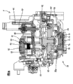
Fig. 2 is a plane, demonstrates the overall structure of internal mechanism;
Fig. 3 is a perspective view, demonstrates the mechanism that is used for rotary driving force is passed to maintenance mechanism;
Fig. 4 is a perspective view, demonstrates the inversion state of balladeur train;
Fig. 5 is the perspective view by watching described maintenance mechanism to draw from the bottom;
Fig. 6 is the bottom view of maintenance mechanism;
Fig. 7 is the top perspective of maintenance mechanism;
Fig. 8 is a schematic cross sectional views, demonstrating wherein block and being in holding fix, switching member and being in the state that valve closed position and doctor are in advanced position;
Fig. 9 is a schematic cross sectional views, and demonstrating wherein, balladeur train is in the tight state of contact in home position and block and balladeur train;
Figure 10 is a schematic cross sectional views, demonstrates the switching member that wherein is used for black and is in the valve open position and is used for the state that colored switching member is in the valve closed position;
Figure 11 is a schematic cross sectional views, demonstrates the switching member that wherein is used for black and is in the valve closed position and is used for the state that colored switching member is in the valve open position;
Figure 12 is the plane of cam, demonstrates wherein to be used for the state that colored switching member is in the valve closed position;
Figure 13 is the plane of cam, demonstrates wherein to be used for the state that colored switching member is in the valve open position;
Figure 14 is a schematic cross sectional views, demonstrates balladeur train wherein and is in state in the idle suction position;
Figure 15 is a schematic cross sectional views, and demonstrating wherein, balladeur train moves to home position and nozzle block and the tight state of contact of balladeur train from idle suction position;
Figure 16 is a schematic cross sectional views, demonstrates the state from the tight ness rating increase that further contacts with balladeur train towards home position motion and nozzle block in the position shown in Figure 15 of balladeur train wherein;
Figure 17 is a schematic cross sectional views, and demonstrating wherein, balladeur train further moves from idle suction position towards the home position and makes exhaust block and the tight state of contact of balladeur train;
Figure 18 is a schematic cross sectional views, demonstrates the state that switching member wherein moves to the valve open position;
Figure 19 A is a schematic plan view, demonstrates when doctor remains in the wiping position position relation between the releasing parts of the cam-follower of doctor and cam;
Figure 19 B is a schematic cross sectional views, demonstrates wherein said doctor and remains on state in the wiping position;
Figure 20 A is a schematic plan view, demonstrates at doctor in wiping position and the position relation between the releasing parts of the cam-follower of bonding part doctor when breaking away from and cam;
Figure 20 B is a schematic cross sectional views, demonstrates the state that doctor wherein breaks away from the bonding part in wiping position;
Figure 21 A is a schematic cross sectional views, demonstrates doctor wherein from the process of wiping position to the advanced position motion;
Figure 21 B is a schematic cross sectional views, demonstrates doctor has wherein moved to advanced position from wiping position state;
Figure 22 is a curve map, demonstrates the position between cam and the switching member, the motion state of switching member, the motion state of balladeur train locking member and the motion state of doctor; And
Figure 23 is the schematic cross sectional views of balladeur train.
The specific embodiment
<the first embodiment 〉
Describe with reference to Fig. 1 to 23 pair of first embodiment of the present invention below.
<overall structure 〉
The ink-jet printer of this embodiment has printer function, duplicator function and scanner functions according to the present invention.As illustrated in fig. 1 and 2, be used for the paper duplicating of duplicator function and scanner functions and the upper surface that scanning means 2 is arranged in main body frame 1.Below this paper duplicating and scanning means 2, be furnished with the balladeur train 3, the ink tank 5 that are used to print operation as will describedly below being used to dredge the maintenance unit 4 of printhead 10 and be used for providing ink to printhead 10.On the front surface of main body frame 1, be furnished with paper collecting disk 6 and sheet feed stacker 7.Balladeur train 3 constitutes along left and right directions and moves back and forth.Print area 8 is defined as from the left end of the motion path of balladeur train 3 and extends near the motion path right-hand member that is positioned at balladeur train 3 position, and maintenance position (home position or original position) is limited to the right-hand member place of the motion path of balladeur train 3.Maintenance unit 4 is arranged at maintenance position.In the maintenance position front (positive front), become side by side relationship to be provided with and be used for black, cyan, magenta and yellow ink tank (print cartridge) 5.
<balladeur train 3 and the member that is used for providing ink〉to balladeur train 3
As shown in figure 23, balladeur train 3 has four printheads 10, and each printhead has a plurality of nozzles on its lower surface.Between 8 moving periods, from the nozzle of corresponding printhead 10, eject ink along print area at balladeur train 3 to go up print data at print media (paper).The nozzle that is used for the printhead 10 of black is positioned at the rectangular area of extending along fore-and-aft direction.Be used for colored for example cyan, magenta and yellow 10 one-tenth side by side relationship of printhead and be positioned at the zone that is formed on the nozzle left side that is used for black.Be used for corresponding cyan, magenta and yellow nozzle quantity is identical, and the quantity of nozzle that is used for black is greater than each nozzle quantity of cyan, magenta and yellow.
In balladeur train 3, be provided with a valve chest 16, it is positioned at the right of printhead 10.Open wide at the lower surface of valve chest 16 from the outlet 18 of the extended exhaust passage 17 of upper wall of corresponding bubble collection chamber 12.These outlets 18 are arranged along fore-and-aft direction.Article four, extend in valve chest 16 along above-below direction exhaust passage 17, is separately installed with normally closed type switch valve 19 in these exhaust passages 17.Because elongated and under the effect of spring 21, valve opening 22 is closed, so each switch valve 19 normally cuts out along the valve body 20 that above-below direction extends.Move upward if valve body 20 overcomes the biasing force of spring 21, then this switch valve 19 is opened.Every the colour that is used for that all extends to the outlet 18 of exhaust passage 17 from bubble collection chamber 12 is that cyan, magenta and yellow exhaust passage (as will describing in detail below) have identical exhaust resistance.On the other hand, the exhaust passage that is used for black has than being used for the colored littler exhaust resistance in exhaust passage.
The balladeur train 3 of Gou Chenging can stop at the home position that is formed on the right-hand member place that moves back and forth passage, be formed on the idle suction position that turn left a little in the home position and doctor 90 is turned right and form the wiping end position place that doctor 90 is turned left a little in it moves back and forth the path of passage like this.
The driving force transmission mechanism of<maintenance unit 4 〉
With reference to Fig. 3, balladeur train framework 110 is provided with the rotary drive mechanism as the member that the feeding-in roll (not shown) is rotated, and it comprises the motor 24 at the left end place that is arranged on balladeur train framework 110.Extend to the right with the rotating shaft 26 of the reduction gearing 25 of the output shaft of motor 24 engagement, thereby and driving gear 27 be arranged on the right-hand member of rotating shaft 26 and rotate integratedly with rotating shaft 26.Balladeur train 29 and driving gear 27 engagements.29 of balladeur trains just mesh with major diameter bevel gear 28 when balladeur train 3 moves to maintenance position.Major diameter bevel gear 28 meshes along the minor diameter bevel gear 30 that above-below direction extends with its axis.
Minor diameter bevel gear 30 is by reduction gearing 31 and central gear 32 engagements.The same as illustrated in Figures 5 and 6, an end of pivotal arm 34 is assemblied on the axle 33 of central gear 32 rotationally.Be rotatably connected on another end of pivotal arm 34 with central gear 32 planet gear meshed 35.In planetary gear 35 fronts, have be parallel to the axis that central gear 32 and planetary gear 35 promptly extend along above-below direction disc cam 55 rotationally by safeguarding that framework 111 supports.Driven gear 36 with height identical with planetary gear 35 forms as one with cam 55.This cam 55 will be elaborated below.
On the other hand, in planetary gear 35 back, the pump gear 37 with height identical with planetary gear 37 is rotationally by safeguarding that framework 111 supports.If pump gear 37 rotates, then drive rotary pump 38 (as aspiration means according to an embodiment of the invention) to carry out suction operation.
If the same central gear 32 as described below rotates along the counter clockwise direction in Fig. 6, then planetary gear 35 meshes along counterclockwise rotating with the driven gear 36 with cam 55 round central gear 32, and along counterclockwise rotating driving cam 55 (when the top is seen, being clockwise direction).On the contrary, if central gear 32 rotates along clockwise direction, then this planetary gear 35 along clockwise direction round central gear 32 rotate with pump gear 37 engagements, and rotation driving pump 38 is to carry out suction operation.Therefore, the rotation of cam 55 is always carried out along the counter clockwise direction in Fig. 6 (clockwise directions in Figure 12 and 13).
The exhaust block 40 of<maintenance unit 4 〉
Block lifting support 41 movably is located to be safeguarded on the framework 111.As Fig. 8,9 with the same shown in 14 to 18, this block promotes support 41 and constitutes according to a kind of like this mode, thereby by can make it at holding fix with closely on left and right directions, move abreast along curved path between the contact position by the 42 pairs of quadric chains that constitute of left and right sides connecting rod that are parallel to each other and have an equal length.Holding fix is lower position, the left side shown in Fig. 8 and 14, and tight contact position is the higher position, the right as shown in Fig. 9 and 17.Block promote support 41 by returning spring 43 bias voltages to holding fix.On the right hand edge of block lifting support 41, be formed with upwardly extending support plate 44.Balladeur train 3 from print area 8 towards the home position (maintenance position) between moving period, just before the home position, this balladeur train 3 contacts with support plate 44 from the left side.Afterwards, when balladeur train 3 arrived the home position, balladeur train 3 these support plates 44 of pushing moved to tight contact position so that block lifting support 41 overcomes the biasing force of returning spring 43 from holding fix.
At the right end position place that is positioned on the block lifting support 41, exhaust block 40 is supported with motion up and down by biasing spring 45.Exhaust block 40 is made by silicon rubber, and has rectangular shape thin and that extend along fore-and-aft direction.Exhaust block 40 has the depression that is open upwards.When block promoted support 41 and is in holding fix, exhaust block 40 remained in the wait state at the height place that is lower than balladeur train 3 lower surfaces.If block promotes that support 41 is promoted towards balladeur train 3 and be inclined upwardly to the right towards tight contact position along curved path and move, the lip that then is formed on the top edge of exhaust block 40 contacts with the lower surface of balladeur train 3 is airtight.Biasing force by biasing spring 45 strengthens the air-tightness between the lower surface of exhaust block 40 and balladeur train 3.By this tight contact, between the lower surface of the depression of exhaust block 40 and balladeur train 3, form and export the airtight space 46 (referring to Figure 17 and 18) that is communicated with four.In the rear end of exhaust block 40, be formed with an inlet 47 of so opening, thereby it can be communicated with depression.Inlet 47 is connected with the exhaust outlet 78 of switching device shifter 70 by pipe.
The switching member 50 of<maintenance unit 4 〉
Four shaft-like switching members 50 arranging along fore-and-aft direction extend up through the lower wall of exhaust block 40, thereby they can slide according to airtight mode and pass exhaust block 40.The switching member that is used for black 50 that is located at backmost (in Figure 12 and 13 topmost and in Figure 10 and 11 the right side) in these four switching members 50 constitutes with respect to exhaust block 40 and moves up and down separately.Be formed with the cam-follower 51 (referring to Figure 14 to 18) that direction is transversely stretched out at switching member 50 places that are used for black.In these four switching members 50, thereby the individual switching member 50 that is used for colour of its excess-three that is arranged in switching member 50 fronts that are used for black is located to interconnect integratedly in its underpart to move up and down.Be formed with another cam-follower 51 that direction is transversely stretched out at three lower ends that are used for the assembly of colored switching member 50.These two cam-followers 51 engage with the cam guide along reciprocating two the front and back sliding parts 52 of left and right directions under the cam effect respectively.These sliding parts 52 will be elaborated below.
<be used for the transmission mechanism of switching member 50 〉
On the upper surface of cam 55, be formed with cam path 56.With the same shown in 13, cam path 56 comprises the non-drive area 56a and the drive area 56b that is connected with non-drive area 56a that has with the concentric curved profile of cam 55 as Figure 12, and has from non-drive area 56a towards cam the profile of 55 central bend.Sliding part 52 is by safeguarding that framework 111 supports according to a kind of like this mode before and after two, thereby they can move above cam 55 individually along left and right directions (they are parallel with the direction of motion of balladeur train 3).The cam-follower 53 that stretches out downwards from respective slide 52 is bonded on the cam path 56 in cam 55 central authorities position to the right.If cam-follower 53 is bonded among the non-drive area 56a of cam path 56, then sliding part 52 remains on (referring to Figure 12) in the wait state in the position on the right, if and cam-follower 53 is bonded among the drive area 56b of cam path 56, then corresponding sliding part 52 slide left (referring to Figure 13).The sliding part 52 of back (above in Figure 12) is used for driving the switching member 50 that is used for black ink, and the sliding part 52 of front is used for driving the switching member 50 that is used for color inks.
Each sliding part 52 is formed with free guiding piece 54a and is used for the cam guide 54b of the cam-follower 51 of engagement switch member 50.Can be easy to find out that free guiding piece 54a extends to form a straight channels along left and right directions (that is, parallel with the direction of motion of sliding part 52) as from Figure 14 to 18, it is neighbouring to form a ramp way to extend up to its right-hand member then.Cam guide 54b is connected with the right-hand member of free guiding piece 54a and has along the upwards sloping portion on inclined-plane to right.
Block promotes support 41 and is in the state in the holding fix therein, even when sliding part 52 is bonded in any of the non-drive area 56a of cam 55 and drive area 56b, the cam-follower 51 of switching member 50 also always is bonded among the free guiding piece 54a, and is bonded on never among the cam guide 54b.If block promotes support 51 and move to tight contact position under the effect of balladeur train 3, then the cam-follower 51 along the switching member 50 that moves integratedly to right and block lifting support 51 engages into cam guide 54b from free guiding piece 54a.At this moment, the cam-follower 53 of sliding part 52 is bonded on non-drive area 56a, the cam-follower 51 of this switching member 50 is bonded in the left end portion of the cam guide 54b at bottom (at the height place identical with the right-hand member of free guiding piece 54a), and switching member 50 remains in the valve closed position corresponding with bottom position.In this valve closed position because its position, upper end of switching member 50 is lower than the lower end of the valve body 20 of switch valve 19, institute so that this switch valve 19 keep closing.
From this state, thereby, the cam-follower 53 of sliding part 52 is bonded among the drive area 56b if sliding left, thereby climb up sloping portion because the cam-follower 51 of switching member 50 moves right along cam guide 54b, so switching member 50 moves up to the valve open position from the valve closed position.If switching member 50 moves to the valve open position, thus then because the upper end of switching member 50 upwards promotes valve body 20 with the following end in contact of valve body 20, so that switch valve 19 stay open.That is to say that switching member 50 moves to the valve open position from the valve closed position in the exhaust passage 17 that is inserted into balladeur train 3 along the direction with the direction of motion perpendicular of balladeur train 3, thereby switch valve 19 is opened.
The nozzle block 60 of<maintenance unit 4 〉
Promote in the support 41 at block, at the place, left side of exhaust block 40, nozzle block 60 is supported by biasing spring 61, thereby it can be along the above-below direction relative motion.This nozzle block 60 is made by silicon rubber, and has the rectangular shape that extends along fore-and-aft direction.Depression about nozzle block 60 has, they are open upwards and wherein accommodate respectively the distance piece 62 with semicircular sectional shape.Block promotes support 41 and is in the state in the holding fix therein, and nozzle block 60 remains in the wait state at the height place of the lower surface that is lower than balladeur train 3.If block promotes that support 41 is promoted towards balladeur train 3 and be inclined upwardly to the right towards tight contact position along curved path and move, the lip that then is formed on the top edge of nozzle block 60 contacts airtightly with the lower surface of balladeur train 3.Biasing force by biasing spring 61 increases the air-tightness between the lower surface of nozzle block 60 and balladeur train 3.By this tight contact, between the lower surface of the upper surface of the distance piece 62 of nozzle block 60 and balladeur train 3, form two independent left and right sides enclosure spaces (referring to Figure 16) that are communicated with the nozzle of printhead 10.The narrower enclosure space in the right that is used for black ink links to each other with the nozzle that is used for black, and the enclosure space that is used for the left side broad of color inks links to each other with the nozzle that is used for those three kinds of colors.
Thereby 64 diapires of setting each depression of passing nozzle block 60 for that enter the mouth are opened the rear end (longitudinal end) that is arranged on diapire and are located.The inlet 64 that is used for the narrower depression of black ink is connected with the port that is used for black ink 79 (being referred to below as " Bk port ") of switching device shifter 70 by pipe, and the inlet 64 that is used for colored broad depression is connected with the port that is used for color inks 80 (being referred to below as " Co port ") of switching device shifter 70 by pipe.Its vertical dimension of each enclosure space (being width) pars intermedia office about enclosure space is minimum and increase gradually towards the left and right end portions of enclosure space.Therefore, when by in enclosure space, forming negative pressure when nozzle passes inlet 64 suction inks, air-flow (including ink) is formed uniformly basically on the whole length of enclosure space, thus the guiding of the left and right end portions (having lower flow resistance) from the width mid portion of enclosure space towards enclosure space.Thereby this air-flow the left and right end portions place of enclosure space compile form towards and guiding inlet port 64 (being formed on the rear end of enclosure space) in air flow.Therefore, 64 be formed in the rear end of the enclosure space that extends along fore-and-aft direction, still make air-flow unanimity on the whole zone of enclosure space, can as one man carry out the ink clear operation to whole nozzle thus though enter the mouth.
The switching device shifter 70 of<maintenance unit 4 〉
As shown in Figure 5, mounting portion 71 defines the circle concentric with cam 55 and driven gear 36.On the external peripheral surface of mounting portion 71, be formed with a plurality of positioning convex 72.This switching member 73 is made by rubber and is had a disc-shape.Switching channel 74 is formed on the outer surface of switching member 73.Switching channel 74 comprises four from the groove 74a of radially extended branch of lower surface central authorities of switching member 73 and form the connection groove 74b that is communicated with the outer end of the groove 74a of branch.This switching member 73 has the positioning convex 72 in the positioning groove 75 that is assembled on the upper surface that is formed on switching member 73, and is assembled to (referring to Fig. 8 and 9) in the mounting portion 71.Thus, can make switching member 73 and cam 55 and driven gear 36 concentric and rotations integratedly.
The cover 76 of Gou Chenging is installed on the cam 55 by the coaptation splint on the lower surface that is formed on cam 55 83 like this.Specifically, flange 84 is formed on the excircle of cover 76 continuously to extend along the whole circumference direction.These three coaptation splints 83 be positioned at the concentric circle of cam 55 on, thereby the predetermined angle in their spaces and can be along the radial direction elastic bending.When on the lower surface that cover 76 is installed in cam 55, three coaptation splints 83 are from the lower surface engages of the excircle and the flange 84 of flange 84.Thus, this cover 76 is supported according to a kind of like this mode, thereby it can rotate and can not move along above-below direction (axial direction of cam 55) with respect to cam 55 and switching member 73.Under cover 76 was installed in situation on the cam 55, switching member 73 was contained in the cover 76, and the lip that is formed on the external peripheral surface of switching member 73 contacts with the inner circumferential surface of cover 76.When cover 76 and switching member 73 relative to each other rotate, between the inner circumferential surface of the lip of switching member 73 and cover 76, produce resistance to sliding (frictional resistance).
The arm 85 that extends along radial direction is formed on the external peripheral surface of cover 76.The far-end of arm 85 is assemblied on the axle 33 of central gear 32 rotationally.Because this assembling of arm 85 on axle 33, thus this cover 76 with respect to safeguarding that framework 111 so keeps, thereby this cover 76 can not directly rotate, and the fixed-site of the port 78 to 82 of this cover 76.Anticreep projection 33a by axle 33 has prevented that this arm 85 from getting loose downwards.Pivotal arm 34 be assemblied in above the arm 85 on the axle 33 between arm 85 and the central gear 32, thereby this pivotal arm 34 can rotate with respect to axle 33.
When switching member 73 rotated in cover 76, switching member 73 remained on that all four of switching member 73 wherein are communicated with state that groove 74b are not communicated with any port 78 to 82 and wherein in the one or more connection groove 74b in these four connection groove 74b and the state that port 78 to 82 is communicated with.All are communicated with in the state that groove 74b does not have with any port 78 to 82 is communicated with therein, and all of the port 78 to 82 disconnects with pump 38.One or three are communicated with in groove 74b and the state that port 78 to 82 is communicated with therein, with be communicated with the port 78 to 82 that groove 74b is communicated with and be communicated with pump 38 by switching channel 74, perhaps be interconnected by switching channel 74 and be communicated with pump 38 with the port 78 to 82 that is communicated with groove 74b connection.To concrete switch mode be described below.
The doctor 90 of<maintenance unit 4 〉
On the upper surface of cam path, be formed with another cam path.This cam path is positioned at the above-mentioned cam path outside that is used for switching member 50 substantially concentricly.Cam path comprises the arch section concentric with cam 55, have the diameter identical with arch section and be formed on a part of arch section with the bossing that extends along circumferencial direction, have the diameter identical with arch section and the release portion that extends along circumferencial direction and be positioned at the release portion outside diametrically and facing to the security of release portion.
This cam path 97 comprises: arch section 97a, and it is concentric and doctor 90 can be remained in the advanced position with cam 55; Extension 97b, it is arranged on the circumferential section with diameter substantially the same with arch section 97a and with doctor 90 interference that remain on advanced position moves to wiping position to promote this doctor and to make it; And release portion 97c, it be arranged on the circumferential section with diameter identical with arch section 97a and with cam-follower 96 radial interference of the doctor 90 that remains on wiping position.
Cam-follower 96 is bonded in the state among the arch section 97a therein, and cam-follower 96 contacts with the upper surface of arch section 97a under the partial pressure of spring 95.At this moment, doctor 90 remains in the advanced position.During near cam-follower 96, this cam-follower 96 makes doctor 90 rise to wiping position on this extension 97b thus at bossing 97b.In the meantime, because doctor 90 is pressed against on the confinement plate 91 and spring 95 tension that is tilted to the left, so when doctor 90 arrival wiping positions, bump bonding 94 engages with bonding part 93, and doctor 90 is remained in the wiping position.
When doctor 90 was in the wiping position, the wiping that is formed on the upper end of doctor 90 partly protruded upward outside the confinement plate 91.In wiping position, doctor 90 contacts with the right surface of confinement plate 91, and cam-follower 96 contacts from the circumferential surface of right side with arch section 97a.In this state, the inclination pulling force that doctor 90 is subjected to spring 95 with along the lower left to extension.Therefore, even when balladeur train 3 is interfered from right side and doctor 90 upper ends (, from home position (maintenance position) towards print area between 8 moving periods), doctor 90 is pressed against on the confinement plate 91, and bump bonding 94 keeps engaging with bonding part 93.At this moment, when doctor 90 is rubbing the nozzle surface of printhead 10, will remove attached to the ink on the nozzle surface.
If balladeur train 3 is interfered from the left side and doctor 90 upper ends, then the attitude along with doctor 90 changes over towards the right side, and bump bonding 94 breaks away from bonding part 93, and under the bias effect of spring 95, and doctor 90 drops to advanced position from wiping position.
The doctor 90 that remains in the wiping position also can drop to advanced position under the effect of the release portion 97c of cam 55.Specifically, if make the following end in contact of conical surface and the cam-follower 96 of release portion 97c by the rotation of cam 55, then because the inclination of conical surface, so thereby the lower end of cam-follower 96 press left and be moved into security 97d.In other words, release portion 97c interferes along radial direction and doctor 90.Afterwards, the lower edge that the attitude of doctor 90 changes over respect to confinement plate 91 is tilted to the right, and bump bonding 94 and bonding part 93 are broken away from.Then, thus the biasing force by spring 95 pulls down doctor 90 and drops in the advanced position.
The balladeur train locking member 100 of<maintenance unit 4 〉
Be formed with the annular flange portion 101 of its lower surface as cam surface 102 at the excircle place of cam 55.The local upwards recessed portion (referring to Fig. 5) that is formed with as the regional 102a of locking on cam surface 102.This cam surface 102 also has the release zone 102b that extends below the regional 102a of locking.Balladeur train locking member 100 is supported according to a kind of like this mode, thereby it can be with respect to safeguarding that framework 111 moves up and down, and by unshowned spring with its bias voltage that makes progress.The cam-follower 103 that is formed on the lower end of balladeur train locking member 100 contacts with cam surface 102 from the bottom.Therefore, most of balladeur train locking member 100 is positioned at above the cam 55.Therein in the 102b state of contact of cam-follower 103 and release zone, balladeur train locking member 100 remains in the following unlocked position, and in cam-follower 103 and the regional 102a state of contact of locking, balladeur train locking member 100 moves up on the motion path of balladeur train 3 therein.At this moment, if balladeur train is in home position (maintenance position), then the upper end of balladeur train locking member 100 engages with the fore-end on the surface, the left side of balladeur train 3.By this joint, prevented that balladeur train 3 is left towards print area 8 motions.
<be used to control the member of the position of rotation of cam 55 〉
On the flange portion on the excircle that is formed on cam 55 101, be furnished with the detected part 105 of rotating integratedly with cam 55.Be provided with a knife switch 106 on the framework 111 safeguarding, thus when cam 55 rotates by detected part 105 with knife switch 106 opening and closing.If knife switch 106 is in open mode or closed condition (i.e. position A (M), N, O, P, Q, R, S and K in Figure 22), then calculate the rotating speed of the motor 24 that is used for driving cam 55, can accurately control the stop position of cam 55 thus.Below in the process explanation that for example maintenance process provides, the relevant explanation that is used to the operation of the position of rotation that opens and closes this knife switch 106 and control cam 55 thus will be omitted.
<block promotes the operation of support 41 along with the motion of support 3 〉
Block promotes support 41 and remains under the partial pressure of returning spring 43 in the state in the advanced position therein, the same as shown in figure 14, if balladeur train 3 moves towards the home position from print area 8, then when balladeur train 3 arrived idle suction position, balladeur train 3 contacted with the support plate 44 that block promotes support 41.At this moment, exhaust block 40 and nozzle block 60 both its positions all are lower than the lower surface of balladeur train 3.That is, exhaust block 40 is blocked a shot 60 boths contacting with the lower surface of balladeur train 3 with nozzle.
In this state, as shown in figure 15, if balladeur train 3 further moves towards the home position, then block lifting support 41 makes progress along the curved path banking motion in the upper right side, and nozzle block 60 contacts with the nozzle surface of printhead 10 in the position in its lower section.Then, as shown in figure 16, if balladeur train 3 moves further to the right, the spring 61 that then is arranged between block lifting support 41 that moves upward and the nozzle block 60 that contacts with the lower surface of balladeur train 3 is subjected to elastic compression, and elastic-restoring force by this spring 61, nozzle block 60 is forced to be pressed on the printhead 10, between nozzle surface and nozzle block 60, form enclosure space thus with the air tight manner positiver sealing.
In this state, as shown in figure 17, if balladeur train 3 moves further to the right and arrives the home position, then exhaust block 40 closely contacts with the lower surface of balladeur train 3, and by being arranged in the elastic force that exhaust block 40 and block promote the biasing spring between the support 41 exhaust block 40 is pressed on the lower surface of balladeur train 3, between the lower surface of balladeur train 3 and exhaust block 40, forms airtight space 46 thus according to the air tight manner positiver sealing.
<exhaust process and idle aspiration procedure in maintenance position 〉
In the starting stage of the process of the bubble exhaust in will being collected in bubble collection chamber 12, balladeur train 3 remains in the home position and by balladeur train locking member 100 and engages to be locked on this home position.Also have, balladeur train 3 is locked in the state on the home position therein, and exhaust block 40 closely contacts with formation airtight space 46 with the lower surface of balladeur train 3.In addition, the position A (M) that cam 55 and switching member 73 remain on Figure 22 locates, and not is not communicated with in atmosphere and the pump 38 any.The enclosure space that is used for black is communicated with atmosphere by the switching channel 74 of switching member 73 with the enclosure space both who is used for colour, and is communicated with pump 38 simultaneously.
In this state, when the position H that turns to Figure 22 at cam 55 and switching member 73 stopped then, airtight space 46 just was communicated with pump 38 by switching member 73.At this moment, be used for the enclosure space of black and be used for colored enclosure space both and be not communicated with and remain on off-state with atmosphere and pump 38.In this state, planetary gear 35 rotates with driving pump 38 round central gear 32, and will be arranged in the air exhaust of airtight space 46, forms negative pressure thus in airtight space 46.
After carrying out the predischarge operation like this, cam 55 and switching member 73 are moved to position I.Between this moving period, be used for the sliding part 52 of black owing to engage to left movement, and the switching member 50 that will be used for black from the valve closed position promotes towards the valve open position upwards with cam 55.Moving upward of switching member 50 by being used for black opened the switch valve 19 that is arranged in the exhaust passage that is used for black.This airtight space 46 just is communicated with, and is used for the enclosure space of black and be used for colored enclosure space both and is not communicated with atmosphere and pump 38 with pump 38, and remains in the off-state.In the I of position, pump 38 is driven, and will be collected in the bubble row of the bubble collection chamber 12 that is used for black to atmosphere by exhaust passage 17, airtight space 46, switching channel and pump 38.In this exhaust process, be used for the enclosure space of black and be used for colored enclosure space remaining on off-state.
Finish if will be collected in the bubble exhaust of the bubble collection chamber 12 that is used for black by pump 38, then cam 55 and switching member 73 move towards position J.Between this moving period, the sliding part 52 that is used for black returns to the right, makes switching member 50 turn back to the valve closed position thus, and the switch valve 19 that will be used for black cuts out.Also have, be used for colored sliding part 52, and will be used for colored switch valve 50 upwards towards the promotion of valve open position, will be arranged in three the colored switch valves 19 that are used for that are used for colored exhaust passage 17 thus and open from the valve closed position to left movement.Also have, as in the situation of position I, 46 of this airtight spaces are communicated with pump 38, and the enclosure space both who is used for the enclosure space of black and is used for colour is being communicated with atmosphere and pump 38, and remain in the off-state.In the J of position, pump 38 is driven in addition, and will be collected in the bubble row of the bubble collection chamber 12 that is used for colour to atmosphere by exhaust passage 17, airtight space 46, switching channel and pump 38.In this exhaust process, be used for the enclosure space of black and be used for colored enclosure space also remaining on off-state.Afterwards, cam 55 and switching member 73 move towards position A.Between this moving period, the colored sliding part 52 that is used for that remains in the valve open mode returns to the right, and is used for colored switching member 50 and turns back to the valve closed position, will be used for colored switch valve 19 thus and close.Like this, finished the operation that will be collected in the bubble exhaust in the bubble collection chamber 12.In this bubble exhaust process, balladeur train 3 remains in the home position.
Afterwards, cam 55 and switching member 73 rotate to position B, and balladeur train locking member 100 descends and is used to limit the state (locking state) of the motion of balladeur train 3 with releasing.Also have, in the B of this position, carry out the connection or the disconnection of airtight space 46 and enclosure space according to the mode identical with position A.If removed the locking state of being realized by balladeur train locking member 100, then balladeur train 3 move from the home position to idle suction position, and exhaust block 40 and nozzle is blocked a shot 60 separate with the lower surface of balladeur train 3.Then, cam 55 and switching member 73 are to position G motion, and the depression that is used for black of nozzle block 60 only is communicated with pump 38, and the depression of exhaust block 40 and nozzle block 60 be used for colored depression and pump 38 disconnections.During cam 55 and switching member 73 rotated towards position G, doctor 90 rose to wiping position from advanced position, and remains in the wiping position owing to bump bonding 94 engages with bonding part 93.At this moment, balladeur train 3 is positioned at doctor 90 the right (towards the home position).
In this state, balladeur train 3 is to left movement.Between this moving period,, will wipe attached to the ink on the nozzle surface by doctor 90 thus at the sliding motion on the top edge of doctor 90 of the nozzle surface on the lower surface of balladeur train 3.Then, if along with balladeur train 3 has been finished wiping operation through doctor 90, then balladeur train 3 just stops at wiping end position place.Afterwards, this balladeur train 3 turns back to idle suction position (towards the home position).At this moment, on left side and doctor 90 during end in contact, doctor 90 drops to advanced position from wiping position at balladeur train 3.After doctor 90 descended, balladeur train 3 stopped at idle suction position place.
So cam 55 and switching member 73 turn to position H.At this moment, balladeur train 3 remains in the idle suction position.Because exhaust block 40 does not contact with balladeur train 3, thus airtight space 46 do not formed, and the depression of exhaust block 40 is communicated with pump 38.If pump 38 is driven, then carry out idle suction operation, thus will be in bleeding from bubble collection chamber 12, be drawn into ink in the exhaust block 40 and be drawn in the pump 38 with to atmospheric exhaust with bubble (air).Like this, the idle suction operation that is through with.
Afterwards, cam 55 and switching member 73 turn to position L.So the depression both who is used for the nozzle block of black and colour is communicated with atmosphere and pump 38.The depression of exhaust block 40 is not communicated with pump 38.In this state, balladeur train 3 turns back to the home position from idle suction position.Thus, exhaust block 40 and balladeur train 3 closely contacts forming airtight space 46 (disconnecting with atmosphere), and nozzle block a shot and 60 closely contact with balladeur train 3, thus the formation enclosure space.Afterwards, cam 55 and switching member 73 turn back to position A (M).Like this, bleeding and idle suction operation have been finished.
<ink clear operation in maintenance position 〉
At the ink that is used for aspirating and discharge the nozzle of blocking printhead 10 be included in starting stage of ink reset procedure of bubble of this ink, balladeur train 3 is locked on the home position, and forms airtight space 46 and enclosure space.Also have, cam 55 and switching member 73 remain among the position A of Figure 22, and the two is communicated with atmosphere and is communicated with pump 38 by switching member 73 to be used for black and colored enclosure space.Airtight space 46 is not communicated with in atmosphere and the pump 38 any, but remains in the off-state.
In this state, cam 55 and switching member 73 turn to position F.Then, be used for black and colored enclosure space both and atmosphere disconnection, and be communicated with pump 38.This airtight space 46 also disconnects with atmosphere and pump 38.In this state, when pump 38 is driven, in pump 38 and switching member 73, form negative pressure (its pressure of the inside of pump 38 and switching member 74 is reduced to and is not more than atmospheric pressure).
Afterwards, cam 55 and switching member 73 turn to position G.Then, the enclosure space that is used for black is communicated with pump 38 by switching member 73, and the black ink that will be collected in thus in the enclosure space (that is, the nozzle block 60) that is used for black is inhaled in the pump 38.At this moment, being used for colored airtight space 46 and enclosure space and pump 38 and atmosphere disconnects.
If having finished the ink that will be arranged in the enclosure space that is used for black removes, then cam 55 and switching member 73 turn to position H, have only airtight space 46 to be communicated with thus, and be used for black and two colored enclosure spaces are not communicated with pump 38, and disconnect with atmosphere with pump 38.
Afterwards, balladeur train 3 just moves from the home position to idle suction position, then to print area 8 motions.At this moment, cam 55 and switching member 73 the same as mentioned above from position A during position F rotates, remain on doctor 90 in the advanced position and raise and be locked on the wiping position to be in the wait state that is used for wiping operation.Therefore, between 3 moving periods, the nozzle surface of printhead 10 contacts with doctor 90 at balladeur train, and will wipe attached to the ink on the nozzle surface.Also have, through after the doctor 90, finished flushing at balladeur train 3.
Afterwards, balladeur train 3 turns back to idle suction position.During this return movement, balladeur train 3 contacts with doctor 90, and doctor 90 drops to advanced position from wiping position thus.Also have, balladeur train 3 turns back in the state of idle suction position therein, owing to exhaust block 40 keeps separating with the lower surface of balladeur train 3 with nozzle block 60, so the not formation of airtight space 46 and enclosure space.
Afterwards, cam 55 and switching member 73 move to position G from position H, and the depression that only is useful on the nozzle block 90 of black thus is communicated with pump 38.And, in this state,, extract out and be removed by pump 38 at the black ink of the enclosure space that is used for black along with pump 38 is driven.Like this, be used for the clear operation of black ink.
Afterwards, cam 55 and switching member 73 turn to position L, and the depression that is used for the enclosure space of black and colour thus is communicated with atmosphere and pump 38.Also have, the depression of exhaust block 40 is not communicated with pump 38.In this state,, carry out idle suction operation once more along with pump 38 is driven.Thus, the ink of staying the switching channel that is communicated with atmospheric air port among the switching channel 74 is removed then by pump 38 sucking-offs.
Afterwards, the balladeur train 3 that remains in the idle suction position turns back to the home position, and forms airtight space 46 and enclosure space.Then, make cam 55 and switching member 73 turn to position A (M).Like this, be through with and be used for the clear operation of black ink.
In addition, be used for the clear operation of color inks according to identical as mentioned above mode.Be used for the clear operation of color inks, beginning to change over position C, D and E respectively from charging into negative pressure to position F, G and H that suction finishes in the clear operation that is used for black ink.Idle suction position G after wiping changes over position D.
In the superincumbent process, though thereby charging into negative pressure is to carry out the ink of sucking-off simultaneously before removing the ink pattern, it is contemplated that to charge under the situation of operation and carry out the ink clear operation not carrying out negative pressure.In this case, having saved wherein balladeur train 3 stops at position F (being used for colored situation, position C) and sentences the process of carrying out suction operation by pump 38.
<wherein balladeur train 3 begins the process of print data on print media 〉
In this case, before driving balladeur train 3, the cam 55 that remains among the A of position moves towards the position that for example arrives between position L and M through position J.At cam 55 from position J towards position L between moving period, the release portion 97c of cam 55 interferes so that doctor 90 drops to advanced position with the doctor 90 that is locked on the wiping position.In this state, though balladeur train 3 from the home position during towards print area 8 motion, balladeur train 3 can not contact with doctor 90 yet, can avoid unnecessary wiping operation thus.
The effect of<embodiment 〉
When (1) bubble in will being collected in bubble collection chamber 12 (air) is discharged, exhaust block 40 closely contacts to form airtight space 46 with balladeur train 3, switch valve 19 is opened so that bubble collection chamber 12 is communicated with airtight space 46 by switching member 50, and will be extracted out with to atmospheric exhaust at the air in the airtight space 46 by pump 38.Therefore, during discharging bubble, air flows to atmosphere to constitute unidirectional flow pattern from bubble collection chamber 12 by airtight space 46 and pump 38.Thus, eliminated the possibility that ambient atmos enters bubble collection chamber 12 and ink channel, and can prevent that air is mixed in the ink.
Also have,, can avoid the ink waste in the present invention and shorten the time that is used to remove bubble when with wherein when the nozzle side of printhead 10 forms negative pressure and is mixed in bubble the ink with sucking-off ink and removing.
(2) be that block 40 of exhaust therein and balladeur train 3 closely contact to carry out in the states that form airtight space 46 owing to make switch valve 19 carry out the valve opening operation by switching member 50, so when disconnecting with atmosphere, prevented that atmosphere is mingled with in the bubble collection chamber 12 in the exhaust passage 17 of bubble.Thus, can prevent ink because the pressure in ink collection chamber 12 raises and overflows from printhead 10.
(3) be lower than atmospheric pressure and between printhead 10 and ink tank 5, exist in the situation of water-head at the pressure of bubble collection chamber 12, airtight space 46 is atmospheric pressure if switch valve is opened simultaneously, then the gas in the airtight space 46 is imported in the air inlet bubble collection chamber 12 increasing the pressure of bubble collection chamber 12, and ink is back to ink tank 5 from printhead 10.But, in this embodiment of the present invention,,, and prevented that ink from refluxing towards ink tank 5 in airtight space 46 so bubble collection chamber 12 remains on the negative pressure place because switch valve 19 is opened in the state of formation negative pressure therein in advance.
(4) because each switching member 50 has the rod-shape of the exhaust of passing block 40 and exhaust block 40 is formed by silicon rubber, thus guaranteed the air-tightness of airtight space 46, and can be reduced in exhaust block a shot 40 and switching member 50 between resistance to sliding.
(5) if under printhead 10 and situation that atmosphere is communicated with, discharge bubble, then owing to causing meniscus destroyed easily at the drop aspect the pressure of bubble collection chamber 12.But, in this embodiment of the present invention, because the bubble exhaust is to carry out owing to nozzle block 60 and balladeur train 3 closely contact in the state that causes printhead 10 and atmosphere to disconnect therein, so can prevent that meniscus is damaged.
(6) in this embodiment of the present invention, be provided with and be used for black and colored two kinds of printheads 10.Therefore, if be provided with a plurality of printheads 10, when then the bubble in will being collected in bubble collection chamber 12 is discharged, because the difference aspect nozzle quantity, nozzle diameter and Mo Dao diameter and black road length is so printhead 10 can have in bubble collection chamber 12 and export the different exhaust resistances of measuring between 18.In this case, if the bubble bleeding is carried out simultaneously for two kinds of printheads 10 with different exhaust resistances, then can produce deviation aspect the bubble capacity of each printhead 10.In view of the above, in embodiments of the invention, owing to the bubble exhaust of being undertaken by pump 38 each for printhead 10 that is used for black and the printhead 10 that is used for colour is carried out separately, so can prevent from aspect the bubble capacity of each printhead 10, to produce deviation.
(7) be identical because be used for three colored printheads 10 aspect nozzle quantity, nozzle diameter, black road diameter and the Mo Dao length, so when the bubble in will being collected in bubble collection chamber 12 is discharged, this printhead 10 have with from bubble collection chamber to exporting 18 identical exhaust resistances.Therefore, in this embodiment of the present invention, because the bubble exhaust is carried out simultaneously for three the colored printheads 10 that are used for same row atmidometer, so can make the bubble capacity in each printhead 10 keep constant and discharge these bubbles effectively.
(8) be used to make the switching member 73 that airtight space 46 switches between the state that is communicated with pump 38 of this airtight space 46 and the state that wherein this airtight space 46 and pump 38 disconnect therein to disconnect, and the cam 55 that is used to make each switching member 50 to move between the valve open position opened of switch valve 19 and the valve closed position that wherein switch valve 19 cuts out therein constitute operation simultaneously with pump.Thus, the switching member 50 that makes it to move by the operation owing to cam 55 opens and closes the operation of switch valves 19 and can carry out according to accurate timing by the operation that the pump 38 that is switched by switching member 73 aspirates bubbles.That is to say, owing to be not used to make the operation and the synchronous independent mechanism of bubble suction operation of switching member 50, so can guarantee designs simplification.
(9) and, because can making between the state of the enclosure space state that is communicated with pump 38 of enclosure space and wherein this enclosure space and pump 38 disconnections therein, switching member 73 switches, so except the operation and bubble suction operation of switching member 50, can aspirate the operation of blocking the ink that is formed on the passage in the nozzle according to accurate timing.
(10) at the switching member 50 that moves between the valve open position opened of switch valve 19 and the valve closed position that wherein switch valve 19 cuts out therein under cam 55 effect, under the effect of cam 55 therein this doctor 90 can wiping attached to the position of the ink on the nozzle of printhead 10 and the doctor 90 wherein operated between the discontiguous position of nozzle of doctor 90 and printhead 10, and the balladeur train locking member 100 that is used for utilizing cam 55 that balladeur train 3 is remained on wherein the home position (being maintenance position) that can bubble be discharged from bubble collection chamber 12 is located at the upper surface relative with switching member 73, and is inserted with next door 55a between them.Thus, can be easy to carry out to arrange on the lower surface of next door 55a the task of extending to the pipe of pump 38, airtight space 46 and enclosure space from the port of the cover 76 that is used for switching member 73.
(11) when and then driving slave unit and for example cam 55 stopped after switching member 50 grades, owing to the load that is applied to from slave unit on the cam 55, so this cam 55 may stop at position out of position.In order to address this problem, in this embodiment of the present invention, switching member 73 is contained in the cover 76 with the port 78 to 82 that is used for exhaust and intake-gas, have the switching channel 74 that can be communicated with, and can on the inner surface of cover 76, rotation slidably keep air-tightness simultaneously with the port 78 to 82 of cover 76.Like this, rotate with respect to the slip of cover 76 because the switching member 73 that rotates integratedly with cam 55 constitutes and to produce frictional resistance, so, can make valve body 20 and cam 55 stop at the pre-position reliably owing to the existence of this frictional resistance.
(12), necessarily must limit this cover 76 and rotate for the fixed-site of port 78 to 82 with respect to the switching member that rotates.Therefore, in this embodiment of the present invention,, be used to rotate the axle 33 of the central gear 32 that drives switching member 73 and cam 55 as the rotation limiting member.Therefore, when comparing, can guarantee designs simplification with the situation that special clamp structure is set.Also have, keep, so cover 76 is rotated with respect to cam 55 because cover 76 is engaged by coaptation splint 83.Therefore, can not cause negative effect to the rotation of cam 55 and switching member 73.
(13) each switching member 50 valve open position motion of can be from valve closed position that switch valve 19 wherein cuts out opening to switch valve 19 wherein, simultaneously along with the direction of motion of balladeur train 3 intersect upward in being inserted into exhaust passage 17.Therefore, (maintenance position) motion while switching member 50 moves towards the valve open position if balladeur train 3 is towards the home position, then the movement interference of this switching member 50 and balladeur train 3.Therefore, in this embodiment of the present invention, when balladeur train 3 is in the print area 8 that is used for print data on print media, this switching member 50 remains in the valve closed position, and when this balladeur train 3 moved to the home position (maintenance position) that is used to discharge bubble, this switching member 50 can move to the valve open position.Thus, balladeur train 3 and switching member 50 interference of moving have been prevented towards the valve open position.
(14) at balladeur train 3 from print area 8 towards the home position (maintenance position) between moving period, balladeur train 3 will be in exhaust block 40 pushings in the holding fix to tight contact position.Therefore, though be not provided for making the member of the synchronized movement of the motion of balladeur train 3 and exhaust block 40, if but balladeur train 3 is then consistent with the motion of this balladeur train 3 towards the maintenance position motion, and exhaust cap cap 40 is closely contacted with balladeur train 3 with correct timing.Also have,, do not need to be used to make the special-purpose drive source of these exhaust block 40 motions because balladeur train 3 constitutes the described exhaust block 40 of pushing.
(15) at balladeur train 3 from print area 8 towards the home position (maintenance position) between moving period, balladeur train 3 will be in nozzle block 60 pushings in the holding fix to tight contact position.Therefore, though be not provided for making the member of the synchronized movement of the motion of balladeur train 3 and nozzle block 60, if but balladeur train 3 is then consistent with the motion of this balladeur train 3 towards the maintenance position motion, and nozzle cover cap 60 is closely contacted with balladeur train 3 with correct timing.Also have,, do not need to be used to make the special-purpose drive source of these nozzle block 60 motions because balladeur train 3 constitutes the described nozzle block 60 of pushing.
(16) initial position of balladeur train 3 (home position) be limited to see from the position of doctor 90 safeguard side and corresponding with maintenance position.In this case, when finishing the balladeur train 3 that remains on after safeguarding in the initial position and move, needn't carry out wiping operation towards the print area 8 that is used for print data on print media.Therefore, in this embodiment of the present invention,, cause separating, on cam 55, be provided with releasing parts 97c with this member with the interference that is produced owing to balladeur train 3 as being used to make doctor 90 to turn back to the member of advanced position from wiping position.This releasing parts 97c engages with doctor 90 so that doctor 90 moves to holding fix from wiping position.Thus, before print area 8 motion, doctor 90 is moved at balladeur train 3 to advanced position from wiping position.As in this case, if do not need then to remove advanced position, thereby avoid doctor 90 and printhead 10 to carry out unnecessary contact by doctor 90 is returned in advance with this doctor 90 wiping printheads 10, can improve the life-span of printhead 10 thus.
(17) releasing parts 97c constitutes along with the substantially parallel direction pushing doctor 90 of the direction of motion of balladeur train 3 doctor 90 and bonding part 93 being broken away from.In other words, make doctor 90 turn back to the member of advanced position as being used to, this releasing parts 97c pushes this doctor 90 according to the mode identical with the situation of wherein balladeur train 3 and doctor 90 interference along doctor 90 and the direction that bonding part 93 breaks away from.Therefore, owing to needn't in cam 55, form owing to the guiding channel that makes doctor 90 towards the advanced position motion forcibly, so can guarantee the designs simplification of cam 55.
(18) cam 55 is by driving with the rotating actuator meshed gears mechanism rotation that is used for paper supply.That is to say that cam 55 has identical drive source with the rotating actuator that is used for paper supply, can further guarantee designs simplification thus.
(19) because be used to make the cam 55 of doctor 90 motions also with acting on member that makes switching member 50 motions and the member that is used to make 100 motions of balladeur train locking member, so can further guarantee designs simplification.
(20) safeguard that framework 111 is provided with a retainer 92, thereby doctor 90 can be between retainer 92 and bonding part 93.Thus, at balladeur train 3 towards the home position (maintenance position) between moving period, when balladeur train 3 be in doctor 90 in the wiping position and interfere and make doctor 90 when the direction that this doctor 90 and bonding part 93 are broken away from is moved, can not cross componental movement thereby this doctor 90 contacts with retainer 92.Therefore, can prevent that other element and doctor 90 from producing unnecessary interference.
(21) owing to utilize biasing member (spring 95) that doctor 90 is remained in this doctor 90 wherein and the wiping position that bonding part 93 engages, so can reliably doctor 90 be remained in the wiping position.
(22) direction of spring 95 bias voltage doctors 90 is along wherein doctor 90 is downward-sloping to the advanced position travel direction from wiping position.Thus, because spring 95 also makes doctor 90 keep the biasing member that engages with bonding part 93 with acting on, so can reduce the quantity of element.
<other embodiment 〉
The invention is not restricted to above-mentioned technology and with reference to the embodiment of these description of drawings.For example, following embodiment also falls within the scope of the invention.Therefore, under the situation that does not break away from the spirit and scope of the present invention, can make various replacements and change.
(1) in the superincumbent embodiment,, can make switch valve carry out the valve opening operation by switching member in that exhaust block and balladeur train are closely contacted with before forming airtight space.
(2) in the superincumbent embodiment, can open these switch valves under the atmospheric pressure in that airtight space is remained on.
(3) in the superincumbent embodiment, exhaust block can be formed by the material beyond the silicon rubber, and arranges rubber seal in the zone of exhaust block and the mutual sliding-contact of switching member therein.
(4) in the superincumbent embodiment, can under printhead and situation that atmosphere communicates, carry out the bubble discharging operation.
(5) in the superincumbent embodiment, the bubble discharging operation can carry out simultaneously for a plurality of printheads with different exhaust resistances.
(6) in the superincumbent embodiment, the bubble discharging operation can carry out separately for a plurality of printheads with same row atmidometer.
(7) in the superincumbent embodiment, after driving switching member and cam separately, its motion can the phase mutually synchronization.
(8) in the superincumbent embodiment, switching member and cam can constitute slip and can not rotate.
(9) in the superincumbent embodiment, switching member can be formed by the material outside the rubber, and this rubber component can be used as independent element and is installed on the inner surface of the outer surface of switching member or cover.
(10) in the superincumbent embodiment, as being used to limit the member that cover rotates, replace the axle of gear, the arm of this cover is equipped with special rotation limiting member.
(11) in the superincumbent embodiment, can on cover or cover and cam, form coaptation splint.
(12) in the superincumbent embodiment, can make the motion of exhaust block by other special-purpose member rather than balladeur train.
(13) in the superincumbent embodiment, can make the motion of nozzle block by other special-purpose member rather than balladeur train.
Claims (18)
1. ink-jet printer comprises:
The balladeur train that can on main body frame, move, it comprises at least one printhead, described printhead is by utilizing nozzle ejection ink print data on print media;
Ink tank, it is storing the ink that will offer printhead; And
The China ink road is used for from ink tank ink being offered printhead,
The switch valve that wherein said balladeur train has the bubble collection chamber that is used for being collected in the bubble that Mo Daozhong produces, be independent of described black road and the exhaust passage that is communicated with bubble collection chamber and be arranged in the exhaust passage and close usually, and
Wherein said main body frame has: switching member, this switching member are configured to motion to open and close described switch valve; Exhaust block, it can closely contact covering the outlet of exhaust passage with balladeur train, thus the airtight space that formation is communicated with described outlet between described exhaust block and balladeur train; And aspiration means, it is the sucking-off air from airtight space.
2. ink-jet printer as claimed in claim 1 wherein carries out the valve opening operation of switch valve by switching member in such state, the exhaust block closely contacts with balladeur train in this state, forms airtight space thus between exhaust block and balladeur train.
3. ink-jet printer as claimed in claim 2, wherein in a kind of like this state, carry out the valve opening operation of switch valve by switching member, in this state by aspiration means since the exhaust block closely contact in the airtight space that forms with balladeur train and produce negative pressure.
4. as each described ink-jet printer among the claim 1-3, wherein said switching member forms shaft-like,
Wherein said switching member passes described exhaust block, and
Wherein said exhaust block is formed by silicon rubber.
5. as each described ink-jet printer among the claim 1-3, wherein be provided with and can closely contact nozzle block with described balladeur train with the nozzle that covers printhead, and
Wherein in closely contact the state that causes printhead and atmosphere disconnection owing to nozzle block and balladeur train, carry out the bubble discharge by aspiration means.
6. as each described ink-jet printer among the claim 1-3, wherein said balladeur train has a plurality of printheads,
Wherein each printhead has the exhaust passage that extends to outlet from bubble collection chamber,
Wherein every exhaust passage has different bubble exhaust resistances when discharge is collected in bubble in the bubble collection chamber, and
Wherein discharging bubble by described aspiration means carries out separately for each printhead.
7. as each described ink-jet printer among the claim 1-3, wherein said balladeur train has a plurality of printheads,
Wherein each printhead has the exhaust passage that extends to outlet from bubble collection chamber,
Wherein every exhaust passage has identical bubble exhaust resistance when discharge is collected in bubble in the bubble collection chamber, and
Discharging bubble by described aspiration means carries out simultaneously for a plurality of printheads.
8. as each described ink-jet printer among the claim 1-3, wherein switching member switches airtight space between the state that state that this airtight space is communicated with aspiration means and this airtight space and aspiration means disconnect,
Its cam is moved switching member between the valve closed position that valve open position that this switch valve is opened and this switch valve are closed, and
Described switching member and cam constitute operation simultaneously.
9. ink-jet printer as claimed in claim 8 wherein is provided with nozzle block, and it can closely contact covering the nozzle of printhead with balladeur train, thereby the enclosure space of printhead is faced in formation between described nozzle block and balladeur train, and
Wherein said switching member constitutes this enclosure space is switched between the state that state that this enclosure space is communicated with aspiration means and this enclosure space and aspiration means disconnect.
10. ink-jet printer as claimed in claim 8,
Wherein doctor can be wiped attached to position and this doctor of the ink on the print-head nozzle at this doctor and and between the print-head nozzle position contacting does not operate by cam,
Wherein the balladeur train locking member remains on balladeur train in the maintenance position by cam, in this maintenance position, can bubble be discharged from bubble collection chamber,
Wherein said switching member, doctor and balladeur train locking member are positioned on the surface in next door, and
Wherein said switching member is positioned on described next door and another a surface described surface opposite.
11. ink-jet printer as claimed in claim 8, wherein said switching member is covered by cover,
Wherein cover has the port that is used to discharge air and sucks air,
Wherein said switching member constitutes has the switching channel that can be communicated with the port of cover, and
Wherein said switching member can slide on the inner surface of cover and keep air-tightness simultaneously.
12. ink-jet printer as claimed in claim 11, wherein said switching member and cam are driven rotatably by gear,
Wherein said cover remains on this cover and can rotate but in the state that can not move along axial direction with respect to cam by engaging with coaptation splint, and
Wherein by the upper-arm circumference that will form with this cover axle assembling, thereby prevent that this cover from directly rotating around this gear.
13. as each described ink-jet printer among the claim 1-3, wherein said switching member constitutes can be when the direction of intersecting with the direction of sledge movements be inserted in the exhaust passage, move to the valve open position of opening described switch valve from the valve closed position of closing described switch valve
Wherein when balladeur train was in the print area that is used for print data on print media, described switching member remained in the valve closed position, and
Wherein when sledge movements during to the maintenance position of can be from bubble collection chamber bubble being discharged, described switching member can move to the valve open position.
14. as each described ink-jet printer among the claim 1-3, wherein said balladeur train can be used at the print area of print data on the print media and be used for discharging from bubble collection chamber between the maintenance position of bubble and move,
Wherein said exhaust block can tight contact position that exhaust block and balladeur train closely contact and exhaust block a shot less than with holding fix that balladeur train contacts between move, and
Wherein said balladeur train constitutes at balladeur train and makes described exhaust block move to tight contact position from holding fix when print area moves to maintenance position.
15. ink-jet printer as claimed in claim 5, wherein said balladeur train can be used at the print area of print data on the print media and be used for discharging from bubble collection chamber between the maintenance position of bubble and move,
Wherein said nozzle block can tight contact position that nozzle block and balladeur train closely contact and nozzle block a shot less than with holding fix that balladeur train contacts between move, and
Wherein said balladeur train constitutes at balladeur train and makes described nozzle block move to tight contact position from holding fix when print area moves to maintenance position.
16. ink-jet printer as claimed in claim 6, wherein said printhead comprise first printhead and second printhead,
Described first printhead has first exhaust passage, and this exhaust passage has the first bubble exhaust resistance,
Described second printhead has second exhaust passage, and this exhaust passage has the second bubble exhaust resistance, and
The first bubble exhaust resistance of wherein said first exhaust passage is lower than the second bubble exhaust resistance of described second exhaust passage.
17. ink-jet printer as claimed in claim 16, wherein said first printhead is used for black ink, and described second printhead is used for color inks.
18. ink-jet printer as claimed in claim 1, wherein said switching member are configured to and can move to the valve open position that is used to open switch valve from the valve closed position that is used to close switch valve.
Applications Claiming Priority (3)
| Application Number | Priority Date | Filing Date | Title |
|---|---|---|---|
| JP2004064568 | 2004-03-08 | ||
| JP2004064568A JP4547943B2 (en) | 2004-03-08 | 2004-03-08 | Inkjet printer |
| JP2004-064568 | 2004-03-08 |
Publications (2)
| Publication Number | Publication Date |
|---|---|
| CN1666874A CN1666874A (en) | 2005-09-14 |
| CN100423944C true CN100423944C (en) | 2008-10-08 |
Family
ID=34824536
Family Applications (2)
| Application Number | Title | Priority Date | Filing Date |
|---|---|---|---|
| CNB2005100527519A Expired - Fee Related CN100423944C (en) | 2004-03-08 | 2005-03-07 | Ink jet printer |
| CNU2005200027640U Expired - Lifetime CN2827728Y (en) | 2004-03-08 | 2005-03-08 | Ink-jet printer |
Family Applications After (1)
| Application Number | Title | Priority Date | Filing Date |
|---|---|---|---|
| CNU2005200027640U Expired - Lifetime CN2827728Y (en) | 2004-03-08 | 2005-03-08 | Ink-jet printer |
Country Status (6)
| Country | Link |
|---|---|
| US (1) | US7452065B2 (en) |
| EP (1) | EP1574341B1 (en) |
| JP (1) | JP4547943B2 (en) |
| CN (2) | CN100423944C (en) |
| AT (1) | ATE387319T1 (en) |
| DE (1) | DE602005004943T2 (en) |
Families Citing this family (28)
| Publication number | Priority date | Publication date | Assignee | Title |
|---|---|---|---|---|
| JP5030423B2 (en) * | 2005-06-23 | 2012-09-19 | エスアイアイ・プリンテック株式会社 | Inkjet head and inkjet recording apparatus |
| JP4566106B2 (en) | 2005-09-30 | 2010-10-20 | ブラザー工業株式会社 | Image recording device |
| JP4419953B2 (en) * | 2005-12-29 | 2010-02-24 | ブラザー工業株式会社 | Image recording device |
| US7878621B2 (en) | 2006-06-15 | 2011-02-01 | Brother Kogyo Kabushiki Kaisha | Ink-jet printer and method of sucking ink from air-discharge cap of ink-jet printer |
| JP5092293B2 (en) * | 2006-07-12 | 2012-12-05 | ブラザー工業株式会社 | Inkjet printer device |
| CN101224668B (en) * | 2007-01-17 | 2010-10-06 | 明基电通股份有限公司 | Ink jet printing device |
| JP2008230137A (en) * | 2007-03-22 | 2008-10-02 | Fujifilm Corp | Back pressure regulating device of liquid discharge head |
| JP5078548B2 (en) * | 2007-10-26 | 2012-11-21 | キヤノン株式会社 | Discharging device and recording device |
| JP4821817B2 (en) | 2008-07-31 | 2011-11-24 | ブラザー工業株式会社 | Droplet ejector |
| US20100302309A1 (en) * | 2009-05-29 | 2010-12-02 | Brother Kogyo Kabushiki Kaisha | Ink Jet Printer |
| JP5482339B2 (en) * | 2010-03-17 | 2014-05-07 | 株式会社リコー | Droplet ejection apparatus and image forming apparatus |
| WO2012014777A1 (en) * | 2010-07-30 | 2012-02-02 | ブラザー工業株式会社 | Liquid cartridge and liquid discharge device |
| US8540341B2 (en) * | 2011-03-02 | 2013-09-24 | Seiko Epson Corporation | Maintenance device, power transmission switching device, and liquid ejecting apparatus |
| JP5765005B2 (en) * | 2011-03-29 | 2015-08-19 | セイコーエプソン株式会社 | inkjet printer |
| JP5811922B2 (en) * | 2012-03-28 | 2015-11-11 | ブラザー工業株式会社 | Droplet ejector |
| JP5978817B2 (en) * | 2012-07-11 | 2016-08-24 | ブラザー工業株式会社 | Inkjet recording device |
| US9757947B2 (en) | 2015-03-31 | 2017-09-12 | Brother Kogyo Kabushiki Kaisha | Liquid ejection apparatus having wiper for wiping ejection surface |
| JP6369374B2 (en) * | 2015-03-31 | 2018-08-08 | ブラザー工業株式会社 | Liquid ejection device |
| JP6365380B2 (en) * | 2015-03-31 | 2018-08-01 | ブラザー工業株式会社 | Liquid ejection device |
| JP6582490B2 (en) * | 2015-03-31 | 2019-10-02 | ブラザー工業株式会社 | Liquid ejection device |
| JP6716258B2 (en) * | 2016-01-08 | 2020-07-01 | キヤノン株式会社 | Recording device, recording device control method, and program |
| CN106379051B (en) * | 2016-08-29 | 2018-10-26 | 合肥菲力姆科技有限公司 | Ink discharge device in medical imaging printer |
| CN107253398A (en) * | 2017-07-05 | 2017-10-17 | 苏州锟恩电子科技有限公司 | A kind of self-cleaning printer nozzle structure |
| CN107264059A (en) * | 2017-07-05 | 2017-10-20 | 苏州锟恩电子科技有限公司 | A kind of cleaning type inkjet printing header structure |
| WO2020101685A1 (en) | 2018-11-15 | 2020-05-22 | Hewlett-Packard Development Company, L.P. | Dispensing aperture hoods |
| US11780236B2 (en) | 2020-12-24 | 2023-10-10 | Seiko Epson Corporation | Liquid ejecting apparatus and control method of liquid ejecting apparatus |
| JP2023066510A (en) * | 2021-10-29 | 2023-05-16 | ブラザー工業株式会社 | Liquid supply device, liquid supply method, and image recording device |
| CN114603998B (en) * | 2022-04-01 | 2023-05-05 | 联想图像(山东)科技有限公司 | Ink cartridge maintenance device and ink jet printing apparatus |
Citations (5)
| Publication number | Priority date | Publication date | Assignee | Title |
|---|---|---|---|---|
| US5812155A (en) * | 1995-10-27 | 1998-09-22 | Hewlett-Packard Company | Apparatus for removing air from an ink-jet print cartridge |
| US6036305A (en) * | 1994-12-28 | 2000-03-14 | Fujitsu, Limited | Ink cartridge with residual ink retaining structure |
| CN2507648Y (en) * | 2001-10-16 | 2002-08-28 | 杭州宏华电脑技术有限公司 | Ink feed device for ink-jet printer |
| CN1091689C (en) * | 1996-03-14 | 2002-10-02 | 精工爱普生株式会社 | Ink-jet recording device and ink box |
| EP1359026A1 (en) * | 2002-04-30 | 2003-11-05 | Hewlett-Packard Company | Re-circulating fluid delivery system |
Family Cites Families (10)
| Publication number | Priority date | Publication date | Assignee | Title |
|---|---|---|---|---|
| US6007184A (en) * | 1990-10-03 | 1999-12-28 | Canon Kabushiki Kaisha | Ink jet recording head mounting and positioning arrangement |
| JP3122323B2 (en) * | 1995-01-13 | 2001-01-09 | キヤノン株式会社 | INK TANK AND INK JET RECORDING APPARATUS EQUIPPED WITH IT |
| US5774141A (en) * | 1995-10-26 | 1998-06-30 | Hewlett-Packard Company | Carriage-mounted inkjet aerosol reduction system |
| JPH10138485A (en) * | 1996-11-14 | 1998-05-26 | Canon Inc | Ink jet head and ink jet device |
| JPH10202904A (en) * | 1997-01-24 | 1998-08-04 | Ricoh Co Ltd | Ink jet recorder |
| JPH11320901A (en) * | 1998-05-12 | 1999-11-24 | Canon Inc | Ink-jet recording apparatus |
| JP2000108383A (en) * | 1998-08-03 | 2000-04-18 | Canon Inc | Device and method for recovering ejection |
| JP2000103084A (en) | 1998-09-29 | 2000-04-11 | Brother Ind Ltd | Ink jet recorder |
| JP2003266742A (en) * | 2002-03-12 | 2003-09-24 | Seiko Epson Corp | Ink jet recorder and method for controlling maintenance of recording head in ink jet recorder |
| JP4348958B2 (en) * | 2003-02-04 | 2009-10-21 | ブラザー工業株式会社 | Inkjet printer and maintenance method thereof |
-
2004
- 2004-03-08 JP JP2004064568A patent/JP4547943B2/en not_active Expired - Fee Related
-
2005
- 2005-03-07 AT AT05251354T patent/ATE387319T1/en not_active IP Right Cessation
- 2005-03-07 CN CNB2005100527519A patent/CN100423944C/en not_active Expired - Fee Related
- 2005-03-07 EP EP05251354A patent/EP1574341B1/en not_active Not-in-force
- 2005-03-07 DE DE602005004943T patent/DE602005004943T2/en active Active
- 2005-03-07 US US11/072,278 patent/US7452065B2/en active Active
- 2005-03-08 CN CNU2005200027640U patent/CN2827728Y/en not_active Expired - Lifetime
Patent Citations (5)
| Publication number | Priority date | Publication date | Assignee | Title |
|---|---|---|---|---|
| US6036305A (en) * | 1994-12-28 | 2000-03-14 | Fujitsu, Limited | Ink cartridge with residual ink retaining structure |
| US5812155A (en) * | 1995-10-27 | 1998-09-22 | Hewlett-Packard Company | Apparatus for removing air from an ink-jet print cartridge |
| CN1091689C (en) * | 1996-03-14 | 2002-10-02 | 精工爱普生株式会社 | Ink-jet recording device and ink box |
| CN2507648Y (en) * | 2001-10-16 | 2002-08-28 | 杭州宏华电脑技术有限公司 | Ink feed device for ink-jet printer |
| EP1359026A1 (en) * | 2002-04-30 | 2003-11-05 | Hewlett-Packard Company | Re-circulating fluid delivery system |
Also Published As
| Publication number | Publication date |
|---|---|
| DE602005004943D1 (en) | 2008-04-10 |
| EP1574341A1 (en) | 2005-09-14 |
| JP4547943B2 (en) | 2010-09-22 |
| CN2827728Y (en) | 2006-10-18 |
| DE602005004943T2 (en) | 2009-03-12 |
| EP1574341B1 (en) | 2008-02-27 |
| ATE387319T1 (en) | 2008-03-15 |
| CN1666874A (en) | 2005-09-14 |
| US20050195246A1 (en) | 2005-09-08 |
| US7452065B2 (en) | 2008-11-18 |
| JP2005246928A (en) | 2005-09-15 |
Similar Documents
| Publication | Publication Date | Title |
|---|---|---|
| CN100423944C (en) | Ink jet printer | |
| EP2617572B1 (en) | Image forming apparatus including liquid ejection head | |
| EP1698466B1 (en) | Imaging forming apparatus | |
| CA2550799A1 (en) | Cartridge unit having negatively pressurized ink storage | |
| JP4479649B2 (en) | Inkjet recording device | |
| JPH08230200A (en) | Service station for ink jet print head | |
| US20050195240A1 (en) | Inkjet printer | |
| US20040104961A1 (en) | Recovery device for ink jet printer | |
| TW200932548A (en) | Printhead nozzle face wiper blade with multiple, inclined contact sections | |
| JP2007331269A (en) | Idle suction method of air discharging cap for inkjet printer | |
| US7878621B2 (en) | Ink-jet printer and method of sucking ink from air-discharge cap of ink-jet printer | |
| US7325911B2 (en) | Ink cartridge and inkjet recording apparatus | |
| US7101027B2 (en) | Inkjet printer | |
| US9085156B1 (en) | Printer | |
| US20120236094A1 (en) | Image forming apparatus including recording head for ejecting liquid droplets | |
| JP4930624B2 (en) | Inkjet printer | |
| JPH10202904A (en) | Ink jet recorder | |
| JP2007331268A (en) | Inkjet printer | |
| JP3589238B2 (en) | Liquid injection device | |
| US8651636B2 (en) | Liquid droplet ejection apparatus | |
| JP4211516B2 (en) | Flow path valve and liquid ejecting apparatus having the flow path valve | |
| JP2009066879A (en) | Liquid injection device | |
| JP2000062207A (en) | Ink-jet recording apparatus | |
| JP2008162038A (en) | Liquid jet device, method for controlling the same, and liquid jet head | |
| JP2004160804A (en) | Image formation device |
Legal Events
| Date | Code | Title | Description |
|---|---|---|---|
| C06 | Publication | ||
| PB01 | Publication | ||
| C10 | Entry into substantive examination | ||
| SE01 | Entry into force of request for substantive examination | ||
| C14 | Grant of patent or utility model | ||
| GR01 | Patent grant | ||
| CF01 | Termination of patent right due to non-payment of annual fee |
Granted publication date: 20081008 |
|
| CF01 | Termination of patent right due to non-payment of annual fee |