CN100419492C - Zoom lens system - Google Patents
Zoom lens system Download PDFInfo
- Publication number
- CN100419492C CN100419492C CNB2004100832095A CN200410083209A CN100419492C CN 100419492 C CN100419492 C CN 100419492C CN B2004100832095 A CNB2004100832095 A CN B2004100832095A CN 200410083209 A CN200410083209 A CN 200410083209A CN 100419492 C CN100419492 C CN 100419492C
- Authority
- CN
- China
- Prior art keywords
- lens
- zoom
- lens combination
- lens system
- focal length
- Prior art date
- Legal status (The legal status is an assumption and is not a legal conclusion. Google has not performed a legal analysis and makes no representation as to the accuracy of the status listed.)
- Expired - Fee Related
Links
Images


Classifications
-
- G—PHYSICS
- G02—OPTICS
- G02B—OPTICAL ELEMENTS, SYSTEMS OR APPARATUS
- G02B15/00—Optical objectives with means for varying the magnification
- G02B15/14—Optical objectives with means for varying the magnification by axial movement of one or more lenses or groups of lenses relative to the image plane for continuously varying the equivalent focal length of the objective
- G02B15/145—Optical objectives with means for varying the magnification by axial movement of one or more lenses or groups of lenses relative to the image plane for continuously varying the equivalent focal length of the objective having five groups only
- G02B15/1451—Optical objectives with means for varying the magnification by axial movement of one or more lenses or groups of lenses relative to the image plane for continuously varying the equivalent focal length of the objective having five groups only the first group being positive
- G02B15/145121—Optical objectives with means for varying the magnification by axial movement of one or more lenses or groups of lenses relative to the image plane for continuously varying the equivalent focal length of the objective having five groups only the first group being positive arranged +-+-+
Abstract
An object is to provide a zoom lens system with a high zoom ratio capable of preferably correcting aberrations with securing sufficient amount of back focal length by well-suited power arrangement. The zoom lens system includes, in order from an object, a first lens group having positive refractive power, a second lens group having negative refractive power, a third lens group having positive refractive power, a fourth lens group having negative refractive power, and a fifth lens group having positive refractive power. When zooming from a wide-angle end state to a telephoto end state, a distance between the first and the second lens groups increases, a distance between the second and the third lens groups decreases, a distance between the third and the fourth lens groups increases and a distance between the fourth and the fifth lens groups decreases. A given conditional expression is satisfied.
Description
Technical field
The present invention relates to a kind of zoom-lens system, and relate to zoom-lens system specifically with high zoom ratios.
Background technology
As zoom-lens system with high zoom ratios, known is the zoom lens of five set types, it begins to comprise in regular turn from object: first lens combination with positive refractive power, second lens combination with negative refractive power, the 3rd lens combination with positive refractive power has the 4th lens combination of negative refractive power and has the 5th lens combination of positive refractive power, for example, Japanese pending application application No.8-179213 and No.9-304697.
But, when structure has the zoom lens of short focal length on by the basis of the disclosed zoom lens of Japanese pending application application No.8-179213, be difficult to guarantee enough back focal length amounts.
In addition, because first lens combination in the disclosed zoom lens of Japanese pending application application No.9-304697, second lens combination, the 3rd lens combination, the 4th lens combination has very strong refractivity, revises aberration and becomes difficult.
Summary of the invention
The present invention has considered that the problems referred to above and target are to provide the zoom-lens system with high zoom ratios, thereby it can preferably revise aberration by the suitable enough back focal length amounts of energy layout assurance.
According to an aspect of the present invention, zoom-lens system begins to comprise in regular turn from object: first lens combination with positive refractive power, second lens combination with negative refractive power has the 3rd lens combination of positive refractive power and has the 4th lens combination of negative refractive power.When the state of lens combination position during from the wide-angle side state transformation to long burnt end state, distance between first lens combination and second lens combination increases, distance between second lens combination and the 3rd lens combination reduces, and the distance between the 3rd lens combination and the 4th lens combination increases.Satisfy following conditions expression formula (1):
0.655<(-f2)/fw<2.000
Wherein f2 represents the focal length of second lens combination, and fw is illustrated in the focal length of zoom-lens system under the wide-angle side state.
According to another aspect of the present invention, zoom-lens system begins to comprise in regular turn from object: have first lens combination of positive refractive power, have second lens combination of negative refractive power and have the 3rd lens combination of positive refractive power.When the state of lens combination position during from the wide-angle side state transformation to long burnt end state, the distance between first lens combination and second lens combination increases, and the distance between second lens combination and the 3rd lens combination reduces.Satisfy the following conditions expression formula:
1.8<BF/fw<6.0
0.655<(-f2)/fw<2.000
Wherein BF is illustrated in the back focal length of zoom-lens system under the wide-angle side state, and f2 represents the focal length of second lens combination, and fw is illustrated in the focal length of zoom-lens system under the wide-angle side state.
The specific descriptions of preferred embodiment in conjunction with the drawings can easily be understood other features and advantages of the present invention.
Description of drawings
Fig. 1 shows the view according to the motion track of the energy layout of the zoom-lens system of each example of the present invention and each lens combination, and wherein W represents that wide-angle side state and T represent long burnt end state.
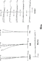
Fig. 2 shows the view of lens arrangement of the zoom-lens system of embodiment according to the present invention 1.
Fig. 3 shows when system focuses at infinity in wide-angle side state (f=18.7), according to the various aberrations of the zoom-lens system of example 1.
Fig. 4 shows when system focuses at infinity in middle focal length state (f=35.0), according to the various aberrations of the zoom-lens system of example 1.
Fig. 5 shows when system focuses at infinity in long burnt end state (f=67.9), according to the various aberrations of example 1 zoom-lens system.
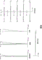
Fig. 6 shows the view of lens arrangement of the zoom-lens system of embodiment according to the present invention 2.
Fig. 7 shows when system focuses at infinity in wide-angle side state (f=18.5), according to the various aberrations of the zoom-lens system of example 2.
Fig. 8 shows when system focuses at infinity in middle focal length state (f=35.0), according to the various aberrations of the zoom-lens system of example 2.
Fig. 9 shows when system focuses at infinity in long burnt end state (f=67.9), according to the various aberrations of the zoom-lens system of example 2.
Figure 10 shows the view of lens arrangement of the zoom-lens system of embodiment according to the present invention 3.
Figure 11 shows when system focuses at infinity in wide-angle side state (f=18.5), according to the various aberrations of the zoom-lens system of example 3.
Figure 12 shows when system focuses at infinity in middle focal length state (f=35.0), according to the various aberrations of the zoom-lens system of example 3.
Figure 13 shows when system focuses at infinity in long burnt end state (f=67.9), according to the various aberrations of the zoom-lens system of example 3.
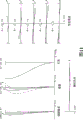
Figure 14 shows the view of lens arrangement of the zoom-lens system of embodiment according to the present invention 4.
Figure 15 shows when system focuses at infinity in wide-angle side state (f=18.5), according to the various aberrations of the zoom-lens system of example 4.
Figure 16 shows when system focuses at infinity in middle focal length state (f=35.0), according to the various aberrations of the zoom-lens system of example 4.
Figure 17 shows when system focuses at infinity in long burnt end state (f=67.9), according to the various aberrations of the zoom-lens system of example 4.
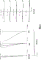
Figure 18 shows the view of lens arrangement of the zoom-lens system of embodiment according to the present invention 5.
Figure 19 shows when system focuses at infinity in wide-angle side state (f=18.5), according to the various aberrations of the zoom-lens system of example 5.
Figure 20 shows when system focuses at infinity in middle focal length state (f=35.0), according to the various aberrations of the zoom-lens system of example 5.
Figure 21 shows when system focuses at infinity in long burnt end state (f=68.9), according to the various aberrations of the zoom-lens system of example 5.
Figure 22 shows the view of lens arrangement of the zoom-lens system of embodiment according to the present invention 6.
Figure 23 shows when system focuses at infinity in wide-angle side state (f=18.5), according to the various aberrations of the zoom-lens system of example 6.
Figure 24 shows when system focuses at infinity in middle focal length state (f=35.0), according to the various aberrations of the zoom-lens system of example 6.
Figure 25 shows when system focuses at infinity in long burnt end state (f=67.9), according to the various aberrations of the zoom-lens system of example 6.
Embodiment
Zoom-lens system according to the present invention begins to comprise in regular turn from object: first lens combination with positive refractive power, second lens combination with negative refractive power, the 3rd lens combination with positive refractive power, the 4th lens combination with negative refractive power has the 5th lens combination of positive refractive power.When the state of lens combination position during from the wide-angle side state transformation to long burnt end state, distance between first lens combination and second lens combination increases, distance between second lens combination and the 3rd lens combination reduces, distance between the 3rd lens combination and the 4th lens combination increases, and the distance between the 4th lens combination and the 5th lens combination reduces.Satisfy following conditions expression formula (1):
0.655<(-f2)/fw<2.000 (1)
Wherein f2 represents the focal length of second lens combination, and fw is illustrated in the focal length of zoom-lens system under the wide-angle side state.
Expression formula (1) has defined the suitable scope of focal length with the ratio of the focal length of second lens combination of zoom-lens system under the wide-angle side state.By satisfying expression formula (1), can easily revise aberration and guarantee good optical property and do not increase the size of this zoom-lens system according to zoom-lens system of the present invention.
In zoom-lens system according to the present invention, when (f2)/and the value of fw is equal to or less than conditional expression (1) following, and it is big that the refractivity of second lens combination becomes in limited time, and making becomes is difficult to revise the curvature of vision area.On the other hand, when (f2)/and the value of fw equals or exceeds going up in limited time of conditional expression (1), and the refractivity of second lens combination diminishes.Because the amount of movement of second lens combination becomes when zoom greatly, zoom-lens system is whole to become big.
In zoom-lens system according to the present invention, preferably the lower limit with conditional expression (1) is made as 0.7.Therefore, because the refractivity of second lens combination diminishes, revise aberration and become easy and can guarantee more superior optical property.
In zoom-lens system according to the present invention, preferably the upper limit with conditional expression (1) is made as 1.0.Therefore, because the refractivity of second lens combination does not become too little, the amount of movement of second lens combination does not increase when zoom too much, makes that zoom-lens system can be compact.
In zoom-lens system according to the present invention, preferably satisfy the optical property of following conditions expression formula (2) with satisfaction guaranted:
1.18<f3/fw<2.50 (2)
Wherein f3 represents the focal length of the 3rd lens combination, and fw is illustrated in the focal length of zoom-lens system under the wide-angle side state.
Conditional expression (2) has defined the suitable scope of focal length with the ratio of the focal length of the 3rd lens combination of zoom-lens system under the wide-angle side state.By satisfying expression formula (2), can easily revise aberration and guarantee good optical property and do not increase the size of this zoom-lens system according to zoom-lens system of the present invention.
In zoom-lens system according to the present invention, it is big that the refractivity of the 3rd lens combination becomes in limited time when the value of f3/fw is equal to or less than conditional expression (2) following, and making becomes is difficult to revise ball-shaped aberration.On the other hand, when the value of f3/fw equals or exceeds going up in limited time of conditional expression (2), the refractivity of the 3rd lens combination diminishes, and makes that zoom-lens system is whole to become big.
In zoom-lens system according to the present invention, preferably the lower limit with conditional expression (2) is made as 1.3.Therefore, because the refractivity of the 3rd lens combination diminishes, the correction aberration becomes easily and further can guarantee more superior optical property.
In zoom-lens system according to the present invention, preferably satisfy the optical property of following conditions expression formula (3) with satisfaction guaranted:
1.92<(-f4)/fw<4.00 (3)
Wherein f4 represents the focal length of the 4th lens combination, and fw is illustrated in the focal length of zoom-lens system under the wide-angle side state.
Conditional expression (3) has defined the suitable scope of focal length with the ratio of the focal length of the 4th lens combination of zoom-lens system under the wide-angle side state.By satisfying expression formula (3), can easily revise aberration and guarantee good optical property and do not increase the size of this zoom-lens system according to zoom-lens system of the present invention.
In zoom-lens system according to the present invention, when (f4)/and the value of fw is equal to or less than conditional expression (3) following, and it is big that the refractivity of the 4th lens combination becomes in limited time, and making becomes is difficult to revise coma aberration.On the other hand, when (f4)/and the value of fw equals or exceeds going up in limited time of conditional expression (3), and the refractivity of the 4th lens combination diminishes.Because the amount of movement of the 4th lens combination becomes when zoom greatly, zoom-lens system is whole to become big.
In zoom-lens system according to the present invention, preferably the lower limit with conditional expression (3) is made as 1.95.Therefore, because the refractivity of the 4th lens combination diminishes, the correction aberration becomes easily and further can guarantee more superior optical property.
In zoom-lens system according to the present invention, preferably satisfy the optical property of following conditions expression formula (4) with satisfaction guaranted:
3.78<f1/fw<6.00 (4)
Wherein f1 represents the focal length of first lens combination, and fw is illustrated in the focal length of zoom-lens system under the wide-angle side state.
Conditional expression (4) has defined the suitable scope of focal length with the ratio of the focal length of first lens combination of zoom-lens system under the wide-angle side state.By satisfying expression formula (4), can easily revise aberration and guarantee good optical property and do not increase the size of this zoom-lens system according to zoom-lens system of the present invention.
In zoom-lens system according to the present invention, it is big that the refractivity of first lens combination becomes in limited time when the value of f1/fw is equal to or less than conditional expression (4) following, and making becomes is difficult to revise axial chromatic aberration.On the other hand, when the value of f1/fw equals or exceeds going up in limited time of conditional expression (4), the refractivity of first lens combination diminishes.Because the amount of movement of first lens combination becomes when zoom greatly, zoom-lens system is whole to become big.
In zoom-lens system according to the present invention, preferably the lower limit with conditional expression (4) is made as 4.00.Therefore, because the refractivity of first lens combination diminishes, the correction aberration becomes easily and further can guarantee more superior optical property.
In zoom-lens system according to the present invention, preferably satisfy the optical property of following conditions expression formula (5) with satisfaction guaranted:
1.8<BF/fw<6.00 (5)
Wherein BF is illustrated in the back focal length of zoom-lens system under the wide-angle side state, and fw is illustrated in the focal length of zoom-lens system under the wide-angle side state.
Conditional expression (5) has defined the suitable scope of the ratio of the back focal length of zoom-lens system under the focal length of zoom-lens system under the wide-angle side state and wide-angle side state.By satisfying expression formula (5), thereby can easily revise aberration and by guaranteeing that enough spaces are used to arrange that mirror and light filter guarantee good optical property and do not increase the size of this zoom-lens system according to zoom-lens system of the present invention.
In zoom-lens system according to the present invention, when the value of BF/fw be equal to or less than conditional expression (5) following in limited time because back focal length diminishes, becoming is difficult to guarantee that enough spaces are used to arrange mirror and light filter.On the other hand, when the value of BF/fw equals or exceeds going up in limited time of conditional expression (5), be to guarantee back focal length, arrange according to the energy of zoom-lens system of the present invention to become the negative focal length type.Therefore, the symmetry variation that energy is arranged, making becomes is difficult to the modified off-axis aberration, such as the curvature and the distortion of vision area.In addition, because back focal length becomes big, zoom-lens system is whole to become big.
In zoom-lens system according to the present invention, preferably the lower limit with conditional expression (5) is made as 1.9.Therefore, because back focal length becomes fully big, guarantee to be used to arrange that the space of mirror and light filter becomes easier.
The zoom-lens system of each example according to the present invention will be explained with reference to the accompanying drawings.
In each example, non-spherical surface is represented by following formula:
x=cy
2/[1+(1-κc
2y
2)
1/2]+C
4y
4+C
6y
6+C
8y
8+C
10y
10
Wherein y represents the height that begins from optical axis, and x represents the sag amount, and c represents the curvature (paraxial curvature) of reference spheroid, and κ represents the taper coefficient, and C
4, C
6, C
8, C
10Represent asphericity coefficient respectively 4,6,8,10 times.
Fig. 1 shows the view according to the motion track of the energy layout of the zoom-lens system of each example of the present invention and each lens combination, and wherein W represents that wide-angle side state and T represent long burnt end state.
The zoom-lens system of each example begins to comprise in regular turn from object according to the present invention: the first lens combination G1 with positive refractive power, the second lens combination G2 with negative refractive power, the 3rd lens combination G3 with positive refractive power, the 4th lens combination G4 with negative refractive power, the 5th lens combination G5 with positive refractive power.When the state of lens combination position during from the wide-angle side state transformation to long burnt end state, distance between the first lens combination G1 and the second lens combination G2 increases, distance between the second lens combination G2 and the 3rd lens combination G3 reduces, distance between the 3rd lens combination G3 and the 4th lens combination G4 increases, and the distance between the 4th lens combination G4 and the 5th lens combination G5 reduces.
<example 1 〉
Fig. 2 shows the view of lens arrangement of the zoom-lens system of embodiment according to the present invention 1.Incidentally, each illustrates the view of lens arrangement, such as Fig. 2, shows the wide-angle side state.
In the zoom-lens system of example 1 according to the present invention, the first lens combination G1 begins to comprise in regular turn from object: will have towards the negative meniscus lens L11 of the convex surface of object with have towards the bonding lens of the bonding formation of positive concave-convex lens L12 of the convex surface of object and have positive concave-convex lens L13 towards the convex surface of object.
The second lens combination G2 begins to comprise in regular turn from object: have the negative meniscus lens L21 towards the convex surface of object, double-concave negative lens L22, biconvex positive lens L23 and have negative meniscus lens L24 towards the concave surface of object.
The 3rd lens combination G3 begins to comprise in regular turn from object: by having towards the negative meniscus lens L31 of the convex surface of object and the bonding lens and the biconvex positive lens L33 of the bonding formation of biconvex positive lens L32.
The 4th lens combination G4 begins to comprise in regular turn from object: have positive concave-convex lens L41 and double-concave negative lens L42 towards the concave surface of object.
The 5th lens combination G5 begins to comprise in regular turn from object: have the positive concave-convex lens L51 towards the concave surface of object, biconvex positive lens L52 and have negative meniscus lens L53 towards the concave surface of object.
In the zoom-lens system of example 1, aperture diaphragm S is arranged in the thing side of the 3rd lens combination G3 and mobile together with the 3rd lens combination G3 in the process that changes the lens combination location status according to the present invention.
In addition, the negative lens L21 of the second lens combination G2 has the thin resin layer of aspherical shape on the thing side surface.
In the zoom-lens system of example 1, carry out focusing by move the second lens combination G2 along optical axis according to the present invention.
Although the motion track of the second lens combination G2 from wide-angle side state W to long burnt end state T is shown in Figure 1 to be straight line, in fact be slight S shape in example 1, the distance in the way that fades to long burnt end state T between the first lens combination G1 and the second lens combination G2 continues to increase rather than reduces.Incidentally, the 4th lens combination G4 fixes in the focusing process.With aperture diaphragm S be arranged in the 3rd lens combination G3 by thing side surface (the 15th surface) on the position at thing side 0.6mm place.This is identical in other example.
Table 1 illustrates the various values according to example 1.In " specification ", f represents focal length, and FNO represents f-number, and 2 ω represent the maximal value (unit: degree) at visual angle.
In " lens data ", " surface number " is the numbering that begins the lens surface of sequential counting from object, r represents the radius-of-curvature of lens surface, d represents the distance of next lens surface, n represents the d-line place (refractive index of λ=587.6nm), v represents the Abbe number at d-line place, and Dn (n: surface number) the variable distance of expression, and BF represents back focal length.
In the form of multiple value, use " mm " as length usually, such as focal length, radius-of-curvature, and the unit of the spacing between the optical surface.But, can obtain similar optical property because amplify in proportion or dwindle optical system, there is no need unit limit also can be used other suitable unit arbitrarily at " mm ".The explanation of reference symbol is identical in other examples.
Table 1
[specification]
The long burnt end state of wide-angle side state middle focal length state
f=18.7 35.0 67.9
FNO=3.6 4.2 4.6
2ω=76.1 43.4 23.1°
[lens data]
Surface number r d n v
1 128.2080 1.80 1.84666 23.8
2 62.1670 6.80 1.64000 60.1
3 7839.7782 0.10 1.00000
4 42.7904 5.30 1.71300 53.9
5 95.6571 D5 1.00000
*6 110.5079 0.08 1.55389 38.1
7 55.0277 1.20 1.80400 46.6
8 11.3585 5.90 1.00000
9 -23.6967 0.90 1.80400 46.6
10 45.6574 0.30 1.00000
11 29.9481 4.10 1.79504 28.5
12 -22.3485 0.80 1.00000
13 -15.5733 0.80 1.80400 46.6
14 -28.1711 D14 1.00000
15 58.1769 0.80 1.80440 39.6
16 15.8142 3.20 1.49782 82.6
17 -68.9654 0.10 1.00000
18 21.2876 3.10 1.48749 70.4
19 -36.7720 D19 1.00000
20 -344.6416 2.20 1.84666 23.8
21 -26.9474 0.28 1.00000
22 -21.8702 1.00 1.83481 42.7
23 54.7759 D23 1.00000
24 -1292.7371 4.80 1.49782 82.5
25 -19.1593 0.10 1.00000
26 54.2606 4.70 1.49782 82.5
27 -32.1957 1.10 1.00000
28 -21.8468 1.10 1.80518 25.4
29 -59.8511 BF 1.00000
[aspherical surface data]
κ=+15.4398
C4=+2.5511×10
-5
C6=-7.9835×10
-9
C8=-2.6853×10
-10
C10=+2.2060×10
-13
[variable range]
The long burnt end state of wide-angle side state middle focal length state
f 18.7 35.0 67.9
D5 2.98 15.56 31.36
D14 15.50 7.83 2.84
D19 0.98 6.94 10.68
D23 11.77 5.82 2.07
[value of conditional expression]
(1)(-f2)/fW=0.748
(2)f3/fW=1.425
(3)(-f4)/fW=2.212
(4)f1/fW=4.209
(5)BF/fW=2.035
Fig. 3 shows when system focuses at infinity, according to the various aberrations of zoom-lens system in wide-angle side state (f-18.7) of example 1.Fig. 4 shows when system focuses at infinity, according to the various aberrations of zoom-lens system in middle focal length state (f=35.0) of example 1.Fig. 5 shows when system focuses at infinity, according to the various aberrations in long burnt end state (f=67.9) of example 1 zoom-lens system.
In each figure, FNO represents f-number, and A represents the visual field half-angle.In the figure that shows astigmatism and distortion, show the maximal value of visual field half-angle A.Reference symbol d, g represent d-line (λ=587.6nm) and g-line (the aberration curvature of λ=435.8nm) locate respectively.
In the figure of spherical aberration was shown, f-number showed value and solid line indication spherical aberration and the dotted line indication sine condition under the situation of maximum diameter of hole.
In the figure of astigmatism was shown, solid line was indicated the radially plane of delineation and dotted line indication warp-wise plane.
Foregoing description about various aberration diagrams is identical with other example.
From each figure, can clearly find out, as in each focal length state (wide-angle side state, middle focal length state and long burnt end state), various aberrations having been made good correction result, demonstrate fabulous optical property according to the zoom-lens system of example 1.
<example 2 〉
Fig. 6 shows the view of lens arrangement of the zoom-lens system of embodiment according to the present invention 2.
In the zoom-lens system of example 2 according to the present invention, the first lens combination G1 begins to comprise in regular turn from object: will have towards the negative meniscus lens L11 of the convex surface of object with have towards the bonding lens of the bonding formation of positive concave-convex lens L12 of the convex surface of object and have positive concave-convex lens L13 towards the convex surface of object.
The second lens combination G2 begins to comprise in regular turn from object: have the negative meniscus lens L21 towards the convex surface of object, double-concave negative lens L22, biconvex positive lens L23 and have negative meniscus lens L24 towards the concave surface of object.
The 3rd lens combination G3 begins to comprise in regular turn from object: will have towards the negative meniscus lens L31 of the convex surface of object and the bonding lens and the biconvex positive lens L33 of the bonding formation of biconvex positive lens L32.
The 4th lens combination G4 begins to comprise in regular turn positive concave-convex lens L41 and the double-concave negative lens L42 that has towards the concave surface of object from object.
The 5th lens combination G5 begins to comprise in regular turn from object: have the positive concave-convex lens L51 towards the concave surface of object, biconvex positive lens L52 and have negative meniscus lens L53 towards the concave surface of object.
In the zoom-lens system of example 2, aperture diaphragm S is arranged in the thing side of the 3rd lens combination G3 and mobile together with the 3rd lens combination G3 in the process that changes the lens combination location status according to the present invention.
In addition, the negative lens L21 of the second lens combination G2 has the thin resin layer of aspherical shape on the thing side surface.
In the zoom-lens system of example 2, carry out focusing by move the second lens combination G2 along optical axis according to the present invention.
Table 2 illustrates the various values according to example 2.
Table 2
[specification]
The long burnt end state of wide-angle side state middle focal length state
f=18.5 35.0 67.9
FNO=3.6 4.2 4.6
2ω=76.8 43.4 23.2°
[lens data]
Surface number r d n v
1 124.3307 1.80 1.84666 23.8
2 61.2506 6.60 1.65160 58.5
3 11530.4910 0.10 1.00000
4 42.3132 5.30 1.71300 53.9
5 88.1999 D5 1.00000
*6 178.2199 0.08 1.55389 38.1
7 70.7402 1.20 1.80400 46.6
8 11.8297 5.50 1.00000
9 -25.0152 0.80 1.80400 46.6
10 62.6799 0.40 1.00000
11 34.6949 4.00 1.79504 28.5
12 -21.9095 1.00 1.00000
13 -16.9368 0.90 1.80400 46.6
14 -37.1720 D14 1.00000
15 88.6663 1.00 1.80440 39.6
16 16.5942 3.20 1.49782 82.6
17 -39.9382 0.10 1.00000
18 19.4599 3.10 1.48749 70.5
19 -46.1789 D19 1.00000
20 -68.6139 2.40 1.84666 23.8
21 -18.6550 0.25 1.00000
22 -16.8011 1.00 1.83481 42.7
23 88.2943 D23 1.00000
24 -212.7464 4.80 1.49782 82.5
25 -17.5848 0.10 1.00000
26 58.1044 4.40 1.49782 82.5
27 -30.0046 1.20 1.00000
28 -19.6715 1.10 1.80518 25.4
29 -48.4471 BF 1.00000
[aspherical surface data]
κ=+1.8114
C4=+2.9226×10
-5
C6=-9.0028×10
-8
C8=+4.1328×10
-10
C10=-6.8112×10
-13
[variable range]
The long burnt end state of wide-angle side state middle focal length state
f 18.5 35.0 67.9
D5 3.10 16.19 31.44
D14 16.22 8.31 3.10
D19 1.37 6.84 10.52
D23 10.48 5.00 1.33
[value of expression formula]
(1)(-f2)/fW=0.755
(2)f3/fW=1.389
(3)(-f4)/fW=2.082
(4)f1/fW=4.257
(5)BF/fW=2.050
Fig. 7 shows when system focuses at infinity, according to the various aberrations of zoom-lens system in wide-angle side state (f=18.5) of example 2.Fig. 8 shows when system focuses at infinity, according to the various aberrations of zoom-lens system in middle focal length state (f=35.0) of example 2.Fig. 9 shows when system focuses at infinity, according to the various aberrations of zoom-lens system in long burnt end state (f=67.9) of example 2.
From each figure, can clearly find out, as in each focal length state (wide-angle side state, middle focal length state and long burnt end state), various aberrations having been made good correction result, show fabulous optical property according to the zoom-lens system of example 2.
<example 3 〉
Figure 10 shows the view of lens arrangement of the zoom-lens system of embodiment according to the present invention 3.
In the zoom-lens system of example 3 according to the present invention, the first lens combination G1 begins to comprise in regular turn from object: will have towards the negative meniscus lens L11 of the convex surface of object with have towards the bonding lens of the bonding formation of positive concave-convex lens L12 of the convex surface of object and have positive concave-convex lens L13 towards the convex surface of object.
The second lens combination G2 begins to comprise in regular turn from object: have the negative meniscus lens L21 towards the convex surface of object, double-concave negative lens L22, biconvex positive lens L23 and have negative meniscus lens L24 towards the concave surface of object.
The 3rd lens combination G3 begins to comprise in regular turn from object: have towards the negative meniscus lens L31 of the convex surface of object and the bonding lens and the biconvex positive lens L33 of the bonding formation of biconvex positive lens L32.
The 4th lens combination G4 begins to comprise in regular turn from object: have positive concave-convex lens L41 and double-concave negative lens L42 towards the concave surface of object.
The 5th lens combination G5 begins to comprise in regular turn from object: have the positive concave-convex lens L51 towards the concave surface of object, biconvex positive lens L52 and have negative meniscus lens L53 towards the concave surface of object.
In the zoom-lens system of example 3, aperture diaphragm S is arranged in the thing side of the 3rd lens combination G3 and mobile together with the 3rd lens combination G3 in the process that changes the lens combination location status according to the present invention.
In addition, the negative lens L21 of the second lens combination G2 has the thin resin layer of aspherical shape on the thing side surface.
In the zoom-lens system of example 3, carry out focusing by move the second lens combination G2 along optical axis according to the present invention.
Table 3 illustrates the various values according to example 3.
Table 3
[specification]
The long burnt end state of wide-angle side state middle focal length state
f=18.5 35.0 67.9
FNO=3.7 4.1 4.7
2ω=76.8 43.5 23.2°
[lens data]
Surface number r d n v
1 110.1817 1.80 1.84666 23.8
2 59.5460 6.20 1.65160 58.5
3 852.0459 0.10 1.00000
4 41.1615 4.80 1.71300 53.9
5 80.9700 D5 1.00000
*6 88.1502 0.05 1.55389 38.1
7 57.9329 1.20 1.80400 46.6
8 10.9809 5.45 1.00000
9 -33.5744 0.80 1.80400 46.6
10 33.4124 0.20 1.00000
11 25.4710 4.40 1.84666 23.8
12 -48.5255 2.00 1.00000
13 -16.8318 0.90 1.80400 46.6
14 -22.7161 D14 1.00000
15 104.5443 1.00 1.84666 23.8
16 27.9277 2.80 1.49782 82.6
17 -31.4669 0.10 1.00000
18 22.0926 2.70 1.48749 70.2
19 -112.7613 D19 1.00000
20 -103.5999 2.60 1.84666 23.8
21 -20.1869 0.25 1.00000
22 -18.0994 1.00 1.83481 42.7
23 67.0711 D23 1.00000
24 -548.6588 4.20 1.49782 82.5
25 -19.5753 0.10 1.00000
26 55.4155 4.00 1.49782 82.5
27 -40.0896 1.30 1.00000
28 -22.7796 1.10 1.80518 25.4
29 -45.7948 BF 1.00000
[aspherical surface data]
κ=+1.8114
C4=+2.9188×10
-5
C6=-7.1082×10
-8
C8=+1.3891×10
-10
C10=+1.3642×10
-13
[variable range]
The long burnt end state of wide-angle side state middle focal length state
f 18.5 35.0 67.9
D5 2.42 15.95 30.20
D14 14.72 7.29 2.36
D19 1.04 7.02 12.17
D23 12.70 6.72 1.57
[value of expression formula]
(1)(-f2)/fW=0.755
(2)f3/fW=1.429
(3)(-f4)/fW=2.195
(4)f1/fW=4.314
(5)BF/fW=2.077
Figure 11 shows when system focuses at infinity, according to the various aberrations of zoom-lens system in wide-angle side state (f=18.5) of example 3.Figure 12 shows when system focuses at infinity, according to the various aberrations of zoom-lens system in middle focal length state (f=35.0) of example 3.Figure 13 shows when system focuses at infinity, according to the various aberrations of zoom-lens system in long burnt end state (f=67.9) of example 3.
From each figure, can clearly see, as in each focal length state (wide-angle side state, middle focal length state and long burnt end state), various aberrations having been made good correction result, show fabulous optical property according to the zoom-lens system of example 3.
<example 4 〉
Figure 14 shows the view of lens arrangement of the zoom-lens system of embodiment according to the present invention 4.
In the zoom-lens system of example 4 according to the present invention, the first lens combination G1 begins to comprise in regular turn from object: will have towards the bonding lens of the negative meniscus lens L11 of the convex surface of object and the bonding formation of biconvex positive lens L12 and have positive concave-convex lens L13 towards the convex surface of object.
The second lens combination G2 begins to comprise in regular turn from object: have the negative meniscus lens L21 towards the convex surface of object, double-concave negative lens L22, biconvex positive lens L23 and have negative meniscus lens L24 towards the concave surface of object.
The 3rd lens combination G3 begins to comprise in regular turn from object: will have towards the negative meniscus lens L31 of the convex surface of object and the bonding lens and the biconvex positive lens L33 of the bonding formation of biconvex positive lens L32.
The 4th lens combination G4 begins to comprise in regular turn from object: have positive concave-convex lens L41 and double-concave negative lens L42 towards the concave surface of object.
The 5th lens combination G5 begins to comprise in regular turn from object: have the positive concave-convex lens L51 towards the concave surface of object, biconvex positive lens L52 and have negative meniscus lens L53 towards the concave surface of object.
In the zoom-lens system of example 4, aperture diaphragm S is arranged in the thing side of the 3rd lens combination G3 and mobile together with the 3rd lens combination G3 in the process that changes the lens combination location status according to the present invention.
In addition, the negative lens L21 of the second lens combination G2 has the thin resin layer of aspherical shape on the thing side surface.
In the zoom-lens system of example 4, carry out focusing by move the second lens combination G2 along optical axis according to the present invention.
Table 4 illustrates the various values according to example 4.
Table 4
[specification]
The long burnt end state of wide-angle side state middle focal length state
f=18.5 35.0 67.9
FNO=3.6 4.1 4.6
2ω=77.3 43.4 23.0°
[lens data]
Surface number r d n v
1 151.2364 1.80 1.84666 23.8
2 62.8398 6.40 1.71300 53.9
3 -1406.5626 0.10 1.00000
4 39.3712 5.00 1.71300 53.9
5 79.7200 D5 1.00000
*6 60.3132 0.05 1.55389 38.1
7 52.8688 1.20 1.83481 42.7
8 10.8038 5.35 1.00000
9 -33.5317 0.80 1.83481 42.7
10 31.7747 0.10 1.00000
11 22.1158 6.65 1.84666 23.8
12 -24.7341 0.65 1.00000
13 -18.7145 0.90 1.83481 42.7
14 -96.7465 D14 1.00000
15 77.5773 1.00 1.84666 23.8
16 22.8979 3.10 1.49782 82.6
17 -29.3394 0.10 1.00000
18 21.6214 3.00 1.48749 70.2
19 -65.7425 D19 1.00000
20 -66.6153 2.60 1.84666 23.8
21 -18.7149 0.25 1.00000
22 -17.0173 1.00 1.83481 42.7
23 78.1841 D23 1.00000
24 -238.6949 4.00 1.60311 60.7
25 -20.3768 0.10 1.00000
26 61.8499 3.95 1.60311 60.7
27 -36.7762 1.05 1.00000
28 -23.6170 1.10 1.80518 25.4
29 -88.5913 BF 1.00000
[aspherical surface data]
κ=+1.8114
C4=+1.2672×10
-5
C6=-3.8269×10
-8
C8=+9.8377×10
-11
C10=-7.3351×10
-14
[variable range]
The long burnt end state of wide-angle side state middle focal length state
f 18.5 35.0 67.9
D5 2.00 13.27 27.99
D14 12.79 6.60 2.75
D19 1.00 7.43 11.52
D23 12.12 5.69 1.60
[value of expression formula]
(1)(-f2)/fW=0.666
(2)f3/fW=1.276
(3)(-f4)/fW=1.993
(4)f1/fW=3.983
(5)BF/fW=2.077
Figure 15 shows when system focuses at infinity, according to the various aberrations of zoom-lens system in wide-angle side state (f=18.5) of example 4.Figure 16 shows when system focuses at infinity, according to the various aberrations of zoom-lens system in middle focal length state (f=35.0) of example 4.Figure 17 shows when system focuses at infinity, according to the various aberrations of zoom-lens system in long burnt end state (f=67.9) of example 4.
From each figure, can it is evident that, as in each focal length state (wide-angle side state, middle focal length state and long burnt end state), various aberrations having been made good correction result, show fabulous optical property according to the zoom-lens system of example 4.
<example 5 〉
Figure 18 shows the view of lens arrangement of the zoom-lens system of embodiment according to the present invention 5.
In the zoom-lens system of example 5 according to the present invention, the first lens combination G1 begins to comprise in regular turn from object: will have towards the bonding lens of the negative meniscus lens L11 of the convex surface of object and the bonding formation of biconvex positive lens L12 and have positive concave-convex lens L13 towards the convex surface of object.
The second lens combination G2 begins to comprise in regular turn from object: have the negative meniscus lens L21 towards the convex surface of object, double-concave negative lens L22, biconvex positive lens L23 and have negative meniscus lens L24 towards the concave surface of object.
The 3rd lens combination G3 begins to comprise in regular turn from object: with biconvex positive lens L31 with have towards the bonding lens of the bonding formation of negative meniscus lens L32 of the concave surface of object and have positive concave-convex lens L33 towards the convex surface of object.
The 4th lens combination G4 begins to comprise in regular turn from object: have positive concave-convex lens L41 and double-concave negative lens L42 towards the concave surface of object.
The 5th lens combination G5 begins to comprise in regular turn from object: have negative meniscus lens L51 towards the convex surface of object, biconvex positive lens L52 and by biconvex positive lens L53 with have bonding bonding lens that constitute of negative meniscus lens L54 towards the concave surface of object.
In the zoom-lens system of example 5, aperture diaphragm S is arranged in the thing side of the 3rd lens combination G3 and mobile together with the 3rd lens combination G3 in the process that changes the lens combination location status according to the present invention.
In addition, the negative lens L21 of the second lens combination G2 has the thin resin layer of aspherical shape on the thing side surface.
In the zoom-lens system of example 5, carry out focusing by move the second lens combination G2 along optical axis according to the present invention.
Table 5 illustrates the various values according to example 5.
Table 5
[specification]
The long burnt end state of wide-angle side state middle focal length state
f=18.5 35.0 68.9
FNO=3.6 4.2 4.7
2ω=77.3 43.1 22.5°
[lens data]
Surface number r d n v
1 284.1586 1.80 1.80518 25.4
2 68.8089 7.15 1.65160 58.5
3 -328.3989 0.10 1.00000
4 47.8822 4.80 1.80400 46.6
5 106.2469 D5 1.00000
*6 88.4245 0.05 1.55389 38.1
7 82.4371 1.20 1.80400 46.6
8 12.3994 5.55 1.00000
9 -36.9229 1.00 1.80400 46.6
10 28.8217 0.10 1.00000
11 23.3428 4.50 1.80518 25.4
12 -83.4963 0.60 1.00000
13 -40.6610 1.80 1.77250 49.6
14 -58.6668 D14 1.00000
15 62.8676 3.05 1.51680 64.1
16 -14.2857 0.80 1.80518 25.4
17 -22.4038 0.10 1.00000
18 28.5651 3.10 1.51680 64.1
19 151.4959 D19 1.00000
20 -58.9618 3.35 1.75520 27.5
21 -14.0975 0.80 1.80400 46.6
22 95.9452 D22 1.00000
23 181.0203 0.80 1.77250 49.6
24 58.9407 1.05 1.00000
25 393.2129 4.55 1.60311 60.7
26 -25.9096 0.10 1.00000
27 59.1555 6.65 1.65160 58.5
28 -23.7409 1.00 1.84666 23.8
29 -91.8950 BF 1.00000
[aspherical surface data]
κ=+0.0000
C4=+7.9215×10
-6
C6=-2.5717×10
-8
C8=-2.1070×10
-11
C10=+3.3289×10
-14
[variable range]
The long burnt end state of wide-angle side state middle focal length state
f 18.5 35.0 68.9
D5 2.44 13.41 30.91
D14 16.33 7.08 2.00
D19 1.93 9.34 14.17
D22 13.29 5.88 1.04
[value of expression formula]
(1)(-f2)/fW=0.802
(2)f3/fW=1.395
(3)(-f4)/fW=2.158
(4)f1/fW=4.443
(5)BF/fW=2.104
Figure 19 shows when system focuses at infinity, according to the various aberrations of zoom-lens system in wide-angle side state (f=18.5) of example 5.Figure 20 shows when system focuses at infinity, according to the various aberrations of zoom-lens system in middle focal length state (f=35.0) of example 5.Figure 21 shows when system focuses at infinity, according to the various aberrations of zoom-lens system in long burnt end state (f=68.9) of example 5.
From each figure, can clearly find out, as in each focal length state (wide-angle side state, middle focal length state and long burnt end state), various aberrations having been made good correction result, show fabulous optical property according to the zoom-lens system of example 5.
<example 6 〉
Figure 22 shows the view of lens arrangement of the zoom-lens system of embodiment according to the present invention 6.
In the zoom-lens system of example 6 according to the present invention, the first lens combination G1 begins to comprise in regular turn from object: will have towards the bonding lens of the negative meniscus lens L11 of the convex surface of object and the bonding formation of biconvex positive lens L12 and have positive concave-convex lens L13 towards the convex surface of object.
The second lens combination G2 begins to comprise in regular turn from object: have the negative meniscus lens L21 towards the convex surface of object, double-concave negative lens L22, biconvex positive lens L23 and have negative meniscus lens L24 towards the concave surface of object.
The 3rd lens combination G3 begins to comprise in regular turn from object: will have towards the negative meniscus lens L31 of the convex surface of object and the bonding lens and the biconvex positive lens L33 of the bonding formation of biconvex positive lens L32.
The 4th lens combination G4 begins to comprise in regular turn from object: have positive concave-convex lens L41 and double-concave negative lens L42 towards the concave surface of object.
The 5th lens combination G5 begins to comprise in regular turn from object: have positive concave-convex lens L51 towards the concave surface of object, biconvex positive lens L52 and by biconvex positive lens L53 with have bonding bonding lens that constitute of negative meniscus lens L54 towards the concave surface of object.
In the zoom-lens system of example 6, aperture diaphragm S is arranged in the thing side of the 3rd lens combination G3 and mobile together with the 3rd lens combination G3 in the process that changes the lens combination location status according to the present invention.
In addition, the negative lens L21 of the second lens combination G2 has the thin resin layer of aspherical shape on the thing side surface.
In the zoom-lens system of example 6, carry out focusing by move the second lens combination G2 along optical axis according to the present invention.
Table 6 illustrates the various values according to example 6.
Table 6
[specification]
The long burnt end state of wide-angle side state middle focal length state
f=18.5 35.0 67.9
FNO=3.6 4.2 4.7
2ω=76.6 43.3 23.1°
[lens data]
Surface number r d n v
1 133.3025 1.80 1.84666 23.8
2 64.0775 6.30 1.65160 58.5
3 -866.3960 0.10 1.00000
4 40.3230 5.10 1.71300 53.9
5 76.7157 D5 1.00000
*6 101.5185 0.05 1.55389 38.1
7 63.6067 1.20 1.83481 42.7
8 11.1203 5.75 1.00000
9 -30.7891 0.80 1.83481 42.7
10 39.3762 0.10 1.00000
11 26.2881 4.10 1.84666 23.8
12 -27.5261 1.30 1.00000
13 -17.8610 0.90 1.83481 42.7
14 -36.3504 D14 1.00000
15 66.0776 1.00 1.84666 23.8
16 24.1930 3.00 1.49782 82.5
17 -33.5672 0.10 1.00000
18 22.5321 2.80 1.48749 70.2
19 -89.0254 D19 1.00000
20 -90.3887 2.60 1.84666 23.8
21 -20.1007 0.25 1.00000
22 -17.9853 1.00 1.83481 42.7
23 61.9801 D23 1.00000
24 -3844.0063 4.40 1.49782 82.5
25 -19.1035 0.10 1.00000
26 62.3257 3.85 1.60311 60.7
27 -39.2402 1.20 1.00000
28 -23.4964 1.10 1.80518 25.4
29 -66.1545 BF 1.00000
[aspherical surface data]
κ=+1.8114
C4=+2.7636×10
-5
C6=-7.0377×10
-8
C8=+1.9801×10
-10
C10=-1.1720×10
-13
[variable range]
The long burnt end state of wide-angle side state middle focal length state
f 18.5 35.0 67.9
D5 2.01 13.67 29.54
D14 14.30 7.27 2.98
D19 0.99 7.39 11.29
D23 11.86 5.46 1.56
[value of expression formula]
(1)(-f2)/fW=0.725
(2)f3/fW=1.353
(3)(-f4)/fW=2.000
(4)f1/fW=4.187
(5)BF/fW=2.077
Figure 23 shows when system focuses at infinity, according to the various aberrations of zoom-lens system in wide-angle side state (f=18.5) of example 6.Figure 24 shows when system focuses at infinity, according to the various aberrations of zoom-lens system in middle focal length state (f=35.0) of example 6.Figure 25 shows when system focuses at infinity, according to the various aberrations of zoom-lens system in long burnt end state (f=67.9) of example 6.
From each figure, can clearly find out, as in each focal length state (wide-angle side state, middle focal length state and long burnt end state), various aberrations having been made good correction result, show fabulous optical property according to the zoom-lens system of example 6.
In the zoom-lens system of each example according to the present invention, although aperture diaphragm S is arranged between the second lens combination G2 and the 3rd lens combination G3, the position of aperture diaphragm S is not limited to this place.For example it can be arranged between the 3rd lens combination G3 and the 4th lens combination G4 or in the 3rd lens combination G3.
In the zoom-lens system of each example, carry out focusing by move the second lens combination G2 along optical axis according to the present invention.But the other lenses group except that the second lens combination G2 also can be applied to carry out focusing.
As mentioned above, the zoom-lens system of each example is made of five lens combination according to the present invention.But lens combination is not limited to this structure, and another lens combination can add in any interval between the adjacent lens group, perhaps adds to any near image-side or object side lens combination.
As mentioned above, in the zoom-lens system of each example, in the second lens combination G2, used non-spherical surface, made and to revise the particularly curvature and the distortion of vision area effectively according to the present invention.But the present invention is not limited to this, and non-spherical surface can be applied in any lens combination except that the second lens combination G2.
In order to prevent from hand-held shooting process, easily to occur in the camera shake of zoom-lens system, by being combined with the zoom-lens system driver, vibration detection device make composition damping optical system become possibility according to the zoom-lens system of each example of the present invention with high zoom ratios.In this combination, detect image motion by vibration detection device at first.Then, be the correction image motion, lens combination or part lens combination in the zoom-lens system departed from as the decentered lens group by driver.Move with correction image because moved image, can prevent the camera shake in hand-held shooting process by this action.
In the zoom-lens system of each example according to the present invention, diffraction optical element can easily be used for any lens surface.Any lens surface of the zoom-lens system by diffraction optical element being applied to each example according to the present invention can preferably be revised particularly aberration.
As mentioned above, the present invention can provide the zoom-lens system with high zoom ratios, thereby it preferably can revise aberration by the suitable enough back focal length amounts of energy layout assurance.In addition, the present invention can provide the zoom-lens system with the high zoom ratios under the short focal length, and it can preferably be revised aberration and arrange enough back focal length amounts that guarantees by suitable energy.
Those of ordinary skills will readily appreciate that other advantage and correction.Therefore, the present invention its widely aspect and typical equipments shown here and described not limited by detail.Therefore, under the situation that does not break away from the spirit or scope of inventive concept as accessory claim and its equivalent are defined, can carry out multiple modification.
Claims (26)
1. zoom-lens system, it begins to comprise in regular turn from object:
First lens combination with positive refractive power;
Second lens combination with negative refractive power;
The 3rd lens combination with positive refractive power;
The 4th lens combination with negative refractive power;
Wherein when the state of lens combination position during from the wide-angle side state transformation to long burnt end state,
Distance between first lens combination and second lens combination increases;
Distance between second lens combination and the 3rd lens combination reduces;
Distance between the 3rd lens combination and the 4th lens combination increases;
The 4th lens combination is fixed;
Second lens combination can move;
Wherein satisfy the following conditions expression formula:
0.655<(-f2)/fw<2.000
Wherein f2 represents the focal length of second lens combination, and fw is illustrated in the focal length of zoom-lens system under the wide-angle side state.
2. zoom-lens system as claimed in claim 1, wherein satisfy the following conditions expression formula:
1.18<f3/fw<2.50
Wherein f3 represents the focal length of the 3rd lens combination.
3. zoom-lens system as claimed in claim 1, wherein satisfy the following conditions expression formula:
1.92<(-f4)/fw<4.00
Wherein f4 represents the focal length of the 4th lens combination.
4. zoom-lens system as claimed in claim 1, wherein satisfy the following conditions expression formula:
3.78<f1/fw<6.00
Wherein f1 represents the focal length of first lens combination.
5. zoom-lens system as claimed in claim 1, wherein satisfy the following conditions expression formula:
1.8<BF/fw<6.0
Wherein BF is illustrated in the back focal length of zoom-lens system under the wide-angle side state.
6. zoom-lens system as claimed in claim 1 further comprises:
Be arranged in the 5th lens combination with positive refractive power of the image-side of the 4th lens combination;
Wherein when the state of lens combination position during from the wide-angle side state transformation to long burnt end state,
Distance between the 4th lens combination and the 5th lens combination reduces.
7. zoom-lens system as claimed in claim 6, wherein satisfy the following conditions expression formula:
1.92<(-f4)/fw<4.00
Wherein f4 represents the focal length of the 4th lens combination.
8. zoom-lens system as claimed in claim 6, wherein satisfy the following conditions expression formula:
3.78<f1/fw<6.00
Wherein f1 represents the focal length of first lens combination.
9. zoom-lens system as claimed in claim 6, wherein satisfy the following conditions expression formula:
1.8<BF/fw<6.0
Wherein BF is illustrated in the back focal length of zoom-lens system under the wide-angle side state.
10. zoom-lens system as claimed in claim 6, wherein second lens combination has at least one non-spherical surface.
11. zoom-lens system as claimed in claim 6 is wherein finished by moving second lens combination from infinite focusing as far as adjacent object.
12. zoom-lens system as claimed in claim 6 wherein satisfies the following conditions expression formula:
1.18<f3/fw<2.50
Wherein f3 represents the focal length of the 3rd lens combination.
13. zoom-lens system as claimed in claim 12 wherein satisfies the following conditions expression formula:
1.92<(-f4)/fw<4.00
Wherein f4 represents the focal length of the 4th lens combination.
14. zoom-lens system as claimed in claim 12 wherein satisfies the following conditions expression formula:
3.78<f1/fw<6.00
Wherein f1 represents the focal length of first lens combination.
15. zoom-lens system as claimed in claim 12 wherein satisfies the following conditions expression formula:
1.8<BF/fw<6.0
Wherein BF is illustrated in the back focal length of zoom-lens system under the wide-angle side state.
16. zoom-lens system as claimed in claim 1, wherein the motion track of second lens combination from the wide-angle side state to long burnt end state is a S shape.
17. zoom-lens system as claimed in claim 6, wherein the 5th lens combination has two positive lenss and a negative lens.
18. zoom-lens system as claimed in claim 6, wherein the 5th lens combination begins to comprise in regular turn object, positive concave-convex lens, biconvex positive lens and negative meniscus lens from object.
19. zoom-lens system as claimed in claim 1, wherein said zoom-lens system is formed vibration reduction optical system.
20. a zoom-lens system, it begins to comprise in regular turn from object:
First lens combination with positive refractive power;
Second lens combination with negative refractive power, this second lens combination can move;
The 3rd lens combination with positive refractive power;
The 4th lens combination, the 4th lens combination is fixed in the focusing process;
When the state of lens combination position during from the wide-angle side state transformation to long burnt end state,
Distance between first lens combination and second lens combination increases;
Distance between second lens combination and the 3rd lens combination reduces;
Wherein satisfy the following conditions expression formula:
1.8<BF/fw<6.0
0.655<(-f2)/fw<2.000
Wherein BF is illustrated in the back focal length of zoom-lens system under the wide-angle side state, and f2 represents the focal length of second lens combination, and fw is illustrated in the focal length of zoom-lens system under the wide-angle side state.
21. zoom-lens system as claimed in claim 20 wherein satisfies the following conditions expression formula:
1.18<f3/fw<2.50
Wherein f3 represents the focal length of the 3rd lens combination.
22. zoom-lens system as claimed in claim 20 wherein satisfies the following conditions expression formula:
3.78<f1/fw<6.00
Wherein f1 represents the focal length of first lens combination.
23. zoom-lens system as claimed in claim 20, wherein second lens combination has at least one non-spherical surface.
24. zoom-lens system as claimed in claim 20 is wherein finished by moving second lens combination from infinite focusing as far as adjacent object.
25. zoom-lens system as claimed in claim 20, wherein the motion track of second lens combination from the wide-angle side state to long burnt end state is a S shape.
26. zoom-lens system as claimed in claim 20, wherein said zoom-lens system is formed vibration reduction optical system.
Applications Claiming Priority (2)
| Application Number | Priority Date | Filing Date | Title |
|---|---|---|---|
| JP341744/2003 | 2003-09-30 | ||
| JP2003341744A JP4525039B2 (en) | 2003-09-30 | 2003-09-30 | Zoom lens |
Publications (2)
| Publication Number | Publication Date |
|---|---|
| CN1603881A CN1603881A (en) | 2005-04-06 |
| CN100419492C true CN100419492C (en) | 2008-09-17 |
Family
ID=34373472
Family Applications (1)
| Application Number | Title | Priority Date | Filing Date |
|---|---|---|---|
| CNB2004100832095A Expired - Fee Related CN100419492C (en) | 2003-09-30 | 2004-09-29 | Zoom lens system |
Country Status (3)
| Country | Link |
|---|---|
| US (1) | US7133213B2 (en) |
| JP (1) | JP4525039B2 (en) |
| CN (1) | CN100419492C (en) |
Families Citing this family (15)
| Publication number | Priority date | Publication date | Assignee | Title |
|---|---|---|---|---|
| JP4717399B2 (en) * | 2004-09-13 | 2011-07-06 | キヤノン株式会社 | Zoom lens and imaging apparatus having the same |
| JP4655205B2 (en) * | 2005-05-26 | 2011-03-23 | ソニー株式会社 | Zoom lens and imaging device |
| JP4876509B2 (en) * | 2005-09-28 | 2012-02-15 | 株式会社ニコン | Zoom lens |
| KR100745509B1 (en) * | 2005-10-13 | 2007-08-02 | 삼성테크윈 주식회사 | Zoom lens having wide angle and high zooming ratio and camera employing the same |
| US7453648B2 (en) * | 2005-11-30 | 2008-11-18 | Panasonic Corporation | Zoom lens system, imaging device and camera |
| JP4982787B2 (en) * | 2006-03-28 | 2012-07-25 | コニカミノルタアドバンストレイヤー株式会社 | Imaging optical system and imaging apparatus |
| JP2008209773A (en) * | 2007-02-27 | 2008-09-11 | Olympus Imaging Corp | Zoom lens, and electronic imaging apparatus using the same |
| JP5028110B2 (en) * | 2007-02-28 | 2012-09-19 | キヤノン株式会社 | Zoom lens and imaging apparatus having the same |
| JP5064837B2 (en) * | 2007-03-01 | 2012-10-31 | キヤノン株式会社 | Zoom lens with anti-vibration function |
| JP2009009104A (en) * | 2007-05-29 | 2009-01-15 | Nikon Corp | Zoom lens and optical apparatus |
| US7804652B2 (en) | 2007-05-30 | 2010-09-28 | Hoya Corporation | Zoom lens system |
| JP5678771B2 (en) * | 2011-03-30 | 2015-03-04 | 株式会社リコー | Zoom lens, camera, and portable information terminal device |
| JP6642789B2 (en) * | 2015-09-24 | 2020-02-12 | キヤノン株式会社 | Zoom lens and imaging device having the same |
| CN108885331B (en) * | 2016-03-29 | 2019-09-24 | 富士胶片株式会社 | Zoom lens and photographic device |
| JP6580003B2 (en) * | 2016-06-28 | 2019-09-25 | 富士フイルム株式会社 | Zoom lens and imaging device |
Citations (3)
| Publication number | Priority date | Publication date | Assignee | Title |
|---|---|---|---|---|
| US5859729A (en) * | 1996-01-06 | 1999-01-12 | Canon Kabushiki Kaisha | Zoom lens device with four lens unit |
| US5886828A (en) * | 1996-12-19 | 1999-03-23 | Samsung Aerospace Industries, Ltd. | Zoom lens system |
| CN1424613A (en) * | 2001-12-12 | 2003-06-18 | 株式会社尼康 | Zoom lens systems |
Family Cites Families (19)
| Publication number | Priority date | Publication date | Assignee | Title |
|---|---|---|---|---|
| JPS5993411A (en) * | 1982-11-19 | 1984-05-29 | Canon Inc | Zoom lens |
| JPS59147314A (en) * | 1983-02-12 | 1984-08-23 | Minolta Camera Co Ltd | Zoom lens system |
| JPS63205628A (en) * | 1987-02-20 | 1988-08-25 | Canon Inc | High variable power ratio zoom lens |
| JPS63266414A (en) * | 1987-04-24 | 1988-11-02 | Canon Inc | Zoom lens of rear focus type |
| US5528427A (en) * | 1991-10-30 | 1996-06-18 | Canon Kabushiki Kaisha | Zoom lens |
| US5523888A (en) * | 1993-09-03 | 1996-06-04 | Canon Kabushiki Kaisha | Zoom lens |
| JP3352263B2 (en) | 1994-12-21 | 2002-12-03 | キヤノン株式会社 | Zoom lens |
| US5781348A (en) * | 1995-09-26 | 1998-07-14 | Nikon Corporation | Zoom lens system |
| JPH09304697A (en) | 1996-05-13 | 1997-11-28 | Canon Inc | Zoom lens |
| JPH10111455A (en) * | 1996-10-07 | 1998-04-28 | Nikon Corp | Zoom lens provided with vibration proof function |
| JPH10111456A (en) * | 1996-10-07 | 1998-04-28 | Nikon Corp | Zoom lens provided with vibration-proof function |
| JPH10111457A (en) * | 1996-10-07 | 1998-04-28 | Nikon Corp | Zoom lens |
| US6028717A (en) * | 1997-06-13 | 2000-02-22 | Minolta Co., Ltd. | Zoom lens system |
| JP3958489B2 (en) * | 2000-02-14 | 2007-08-15 | オリンパス株式会社 | Zoom lens |
| JP2001242380A (en) * | 2000-02-25 | 2001-09-07 | Olympus Optical Co Ltd | Photographing lens and zoom lens having image blurring correcting function |
| JP2001249276A (en) * | 2000-03-03 | 2001-09-14 | Olympus Optical Co Ltd | Photographic lens with image blurring correcting function |
| JP4156777B2 (en) * | 2000-05-23 | 2008-09-24 | オリンパス株式会社 | Zoom lens |
| JP2002162563A (en) * | 2000-11-24 | 2002-06-07 | Matsushita Kotobuki Electronics Industries Ltd | Zoom lens |
| JP4813670B2 (en) * | 2001-01-30 | 2011-11-09 | パナソニック株式会社 | Zoom lens and video camera using the same |
-
2003
- 2003-09-30 JP JP2003341744A patent/JP4525039B2/en not_active Expired - Fee Related
-
2004
- 2004-09-29 CN CNB2004100832095A patent/CN100419492C/en not_active Expired - Fee Related
- 2004-09-29 US US10/951,871 patent/US7133213B2/en active Active
Patent Citations (3)
| Publication number | Priority date | Publication date | Assignee | Title |
|---|---|---|---|---|
| US5859729A (en) * | 1996-01-06 | 1999-01-12 | Canon Kabushiki Kaisha | Zoom lens device with four lens unit |
| US5886828A (en) * | 1996-12-19 | 1999-03-23 | Samsung Aerospace Industries, Ltd. | Zoom lens system |
| CN1424613A (en) * | 2001-12-12 | 2003-06-18 | 株式会社尼康 | Zoom lens systems |
Also Published As
| Publication number | Publication date |
|---|---|
| JP2005107262A (en) | 2005-04-21 |
| CN1603881A (en) | 2005-04-06 |
| US7133213B2 (en) | 2006-11-07 |
| US20050068636A1 (en) | 2005-03-31 |
| JP4525039B2 (en) | 2010-08-18 |
Similar Documents
| Publication | Publication Date | Title |
|---|---|---|
| JP4604303B2 (en) | Variable focal length lens system and imaging apparatus including the lens system | |
| JP4317928B2 (en) | Zoom lens | |
| US4934796A (en) | Zoom lens | |
| CN100419492C (en) | Zoom lens system | |
| US7253964B2 (en) | Zoom lens system | |
| JP4366932B2 (en) | Zoom lens | |
| JPH08327907A (en) | Zoom lens | |
| JPH05173071A (en) | Wide angle zoom lens | |
| US7365913B2 (en) | Zoom lens system and camera incorporating the same | |
| US4991942A (en) | Zoom lens | |
| JP3849129B2 (en) | Zoom lens | |
| US6118593A (en) | Zoom lens and optical apparatus having the same | |
| JP3465036B2 (en) | Zoom lens | |
| JP4096399B2 (en) | Large aperture zoom lens | |
| US5583699A (en) | Rear-focus zoom lens system | |
| JP6583420B2 (en) | Zoom lens and optical equipment | |
| US5493447A (en) | Small-sized zoom lens | |
| JP3376143B2 (en) | Zoom lens | |
| JP3352248B2 (en) | Zoom lens | |
| JP3743362B2 (en) | Variable focal length lens | |
| JPH08190052A (en) | Zoom lens capable of focusing at short distance | |
| JP3473161B2 (en) | Zoom lens | |
| JP6808326B2 (en) | Zoom lens and imaging device with it | |
| WO2021039812A1 (en) | Optical system, optical device, and method for manufacturing optical system, and variable power optical system, optical device, and method for manufacturing variable power optical system | |
| JP4466028B2 (en) | Variable focal length lens |
Legal Events
| Date | Code | Title | Description |
|---|---|---|---|
| C06 | Publication | ||
| PB01 | Publication | ||
| C10 | Entry into substantive examination | ||
| SE01 | Entry into force of request for substantive examination | ||
| C14 | Grant of patent or utility model | ||
| GR01 | Patent grant | ||
| CF01 | Termination of patent right due to non-payment of annual fee |
Granted publication date: 20080917 Termination date: 20210929 |
|
| CF01 | Termination of patent right due to non-payment of annual fee |