Receiving machine and method with signal path
Technical field
The present invention relates to a kind of receiver, comprise following elements: tuner with signal path; Demodulator circuit, be used to provide have base band stereophonic sum signal (L+R), 19kHz stereo pilot and the stereo multiplex signal of the stereophonic difference signal (L-R) of amplitude modulation double side band on the 38kHz of blank subcarrier; Be used for analog signal conversion is become the sampling apparatus of discretely-timed signal; And have filter and comprise the stereodecoder of the phase-locked loop of oscillator.
Background technology
Can from EP 0512606B1, learn this receiver.In the UHF of 88-108MHz scope, the RF signal is launched as FM signal.Most station emission stereophonic signal.After demodulation RF FM signal, obtain stereo multiplex signal, this signal have in the 15kHz scope base band stereophonic sum signal (L+R) and on the blank subcarrier of 38kHz the stereophonic difference signal (L-R) of amplitude modulation double side band.And signal (L+R) is also referred to as monophonic signal.The demodulation of stereophonic difference signal (L-R) need have the receiver of a large amount of circuit units.This receiver comprises the phase-locked loop by stereo pilot control.When the frequency change of transmitter, stereo pilot also changes.Readjust the demodulator in the receiver.Because these unwanted frequencies change, and are placed on before the stereodecoder so will abbreviate the sampling rate converter of SRC as.Second sampling frequency converter is after stereodecoder.These transducers are accurate.
Summary of the invention
Therefore, the purpose of this invention is to provide a kind of simple stereodecoder.According to an aspect of the present invention, provide a kind of receiver, comprise following elements: tuner with signal path; Demodulator circuit is used to provide have base band stereophonic sum signal (L+R), 19kHz stereo pilot, and on the 38kHz of blank subcarrier the stereo multiplex signal of the stereophonic difference signal (L-R) of amplitude modulation double side band; Be used for analog signal conversion is become the sampling apparatus of discretely-timed signal; And stereodecoder, it has a plurality of finite impulse response filters, the phase-locked loop that comprises oscillator, and a plurality of modulators, it is characterized in that described stereodecoder also comprises transducer, first finite impulse response filter in wherein said a plurality of finite impulse response filter carries out filtering to described stereo multiplex signal, wherein by means of the inclined-plane in the finite impulse response filter frequency response to two stereophonic signal (L+R, L-R) one in is carried out complex filter, first modulator in described a plurality of modulator carries out multiple modulation to filtered signal, second finite impulse response filter in described a plurality of finite impulse response filter carries out filtering to the signal after modulating, wherein by means of the inclined-plane in the finite impulse response filter frequency response to two stereophonic signal (L+R, L-R) another in carries out complex filter, second modulator in described a plurality of modulator carries out multiple modulation to signal, third and fourth finite impulse response filter in described a plurality of finite impulse response filter separates base band stereophonic sum signal (L+R) and stereophonic difference signal (L-R), the 3rd modulator in described a plurality of modulator to (L+R) and (1-R) signal modulate, and described transducer is converted to real number signal with signal from complex signal.
According to a further aspect in the invention, a kind of method of in the decoder of receiver time-discrete stereo multiplex signal being decoded is provided, this stereo multiplex signal has base band stereophonic sum signal (L+R), the 19kHz stereo pilot, and on the 38kHz of blank subcarrier the stereophonic difference signal (L-R) of amplitude modulation double side band, it is characterized in that the method comprising the steps of: stereo multiplex signal is carried out filtering by finite impulse response filter, wherein by means of the inclined-plane in the finite impulse response filter frequency response to two stereophonic signal (L+R, L-R) one in is carried out complex filter, filtered signal is carried out first modulation step of multiple modulation by modulator, by finite impulse response filter the signal after modulating is carried out filtering, wherein by means of the inclined-plane in the finite impulse response filter frequency response to two stereophonic signal (L+R, L-R) another in carries out complex filter, signal is carried out second modulation step of multiple modulation, separate base band stereophonic sum signal (L+R) and stereophonic difference signal (L-R) by two finite impulse response filters, to (L+R) and (1-R) signal the 3rd modulation step of modulating, and signal is converted to real number signal from complex signal.
According to the present invention, can in plural scope, carry out the operation of filter.The frequency response edge is near the plural scope of 0Hz.The real number input signal of carrying out in cycle a period of time and the multiplication of cosine wave have produced in frequency range the result to the both sides skew, that is, carrier frequency+/-modulation around the φ:
Y(e
iθ)=(X(e
i(θ-φ))+X(e
i(θ+φ)))/2
Produce an output signal by means of the modulation of the cosine wave with carrier frequency φ, wherein near the nonuseable part that is transfused in the frequency spectrum+/-2 φ of useful part replenishes.This can by means of one can suppress in the frequency spectrum+near the prefilter of nonuseable part/-2 φ avoids.This is equally applicable to adopt sinusoidal wave modulation.
Real number or complex signal utilize complex exponential e
I θ n, promptly multiply each other with imaginary exponent, only cause the lateral deviation in frequency range to be moved, therefore do not use prefilter.
Y(e
iθ)=(X(e
i(θ-φ))
In this stereodecoder, multiple modulation is to realize by signal cos that is provided by oscillator (n φ) and sin (n φ).Non-recursive half-band filter, that is, finite impulse response filter abbreviates the FIR filter as, has the characteristic of pi/2 phase shift.This pi/2 phase shift is also referred to as 90 degree phase shifts or is called secondary reflection (quadratic mirroring).The term secondary reflection represents that the transfer function H (f) of this class filter can be according to be reflected 1/4th (Fs/4) of sample frequency of following equation.
|H(Fs/4-f)|+|H(Fs/4+f)|=1
Term half band is meant second characteristic of FIR filter, represents that promptly these filters play reduction and/or interpolation.The FIR filter has a characteristic that merits attention, and its half coefficient is zero.When being used to reduce, this means that in digital technology each second value is removed in form.For interpolation, this means second value, promptly previous value is inserted in after each value in the form.The twice reduction is also referred to as 2 samplings (down-sampling by 2) that descend.
The 3rd characteristic that merits attention of this FIR filter is when designated length is odd number, and delay is the integral multiple of sampling.When these FIR filters are used in combination with multiple modulation, only insert simple delay element, thereby make that the multiple modulation in stereodecoder is a homophase in the different time.The transfer function of FIR filter of stereodecoder that is used for complex signal is in 1/4th of frequency range bias internal sample frequency, thereby makes the transition band that is also referred to as the inclined-plane hereinafter to be the center near the 0Hz frequency, that is, and and at f
0Near=0, and with L+R and L-R spectrum overlapping, when using these filter time-frequency spectrum also can be with f
0=0 is the center.Analogize value f with direct current
0=0 is also referred to as DC, and it has zero frequency at the voltage place that applies.Because reflection characteristic can assign to recover L+R and L-R signal by the real part that connects this signal.
The transfer function of FIR filter is meant that in 1/4th of frequency range bias internal sample frequency the coefficient of this real number FIR filter revises with following manner:
h[n]→h[n]e
inπ/2
The modification of these coefficients is for realizing that the FIR filter does not have other influence.
Three characteristics of this of the FIR filter that combines with multiple modulation are perfect keys that solve stereodecoder.
Description of drawings
With reference to the embodiment that describes hereinafter, these and other aspect of the present invention will be elaborated and become clear.
In the accompanying drawings:
Fig. 1 is the block diagram that comprises the receiver of stereodecoder,
Fig. 2 has shown first frequency spectrum at the input end of stereodecoder,
Fig. 3 has shown the frequency response of first frequency spectrum and the first half bands or FIR filter,
Fig. 4 has shown second frequency spectrum at the output of a FIR filter,
Fig. 5 has shown the 3rd frequency spectrum at the output of first modulator,
Fig. 6 has shown the frequency response of the 3rd frequency spectrum and the 2nd FIR filter,
Fig. 7 has shown the 4th frequency spectrum at the output of the 2nd FIR filter,
Fig. 8 has shown the 5th frequency spectrum at the output of second modulator,
Fig. 9 has shown the FIR high pass of the 5th frequency spectrum and symmetry and two frequency responses in addition of low pass filter,
Figure 10 has shown the 6th frequency spectrum at first output of the FIR of symmetry high pass and low pass filter,
Figure 11 has shown the 7th frequency spectrum at second output of the FIR of symmetry high pass and low pass filter,
Figure 12 has shown the pilot tone at the output of elliptic filter,
Figure 13 has shown the 8th frequency spectrum at the plural L+R signal of having of the output of the 3rd modulator,
Figure 14 has shown the 9th frequency spectrum at the plural L-R signal of having of the output of the 4th modulator,
Figure 15 has shown the tenth frequency spectrum at the real number L+R of the output of first transducer signal,
Figure 16 has shown the 11 frequency spectrum at the real number L-R of the output of second transducer signal,
Figure 17 is the block diagram of phase-locked loop, and
Figure 18 is the block diagram of oscillator.
Embodiment
Fig. 1 has shown stereodecoder 1, and it has finite impulse response (FIR) or FIR filter 2, complex modulator 3, the 2nd FIR filter 4, second complex modulator 5,2 sampling filters 6 descend, circuit 7 with two FIR filters 8 and 9, third and fourth modulator 10 and 11, two other descend 2 sampling filters 12 and 13, two transducers 14 and 15, oval low pass filter 16, control access 17, two-fold interpolation filter 18, oscillator 19, delay element 20, the 5th decline 2 sampling filters 21, second delay element 22, the 6th decline 2 sampling filters 23, and the 3rd delay element 24.In stereodecoder 1, input signal connects 25 by conduction and is provided to FIR filter 2.Two conductions in addition connect 26 and guide modulator 3 into from FIR filter 2, and from FIR filter 2 signal are provided to modulator 3.Signal from modulator 3 is provided to the 2nd FIR filter 4 by two electrically conductive signals connections 27.Signal by other connects 27 to 36, and by FIR filter 4, modulator 5, FIR filter 8 and 9, modulator 10 and 11, descend 2 sampling filters 12 and 13 and transducer 14 and 15, signal further is provided to output 37 and 38.Connecting 26 to 36 is two parallel connections, and each connection transmits a signal.
Oscillator 19 is oscillators of discrete control, abbreviates DCO as.DCO 19 has three and has the output 39 to 41 that two electrically conductive signals connect, and they lead to complex modulator 3; Be connected 42 with another by delay element 20 and lead to modulator 5, and by the 2 sampling filters 21 that descend with second delay element 22 and be connected 43 and 44 and lead to modulator 10; By being connected of FIR filter 4, descend 2 sampling filters 23 and the 3rd delay element 24 and other 45,46 and 47 leading to modulator 11.DCO 19 connects the generation cosine signal and produce sinusoidal signal on another signal connects at a signal of output.Signal is connecting the frequency that has 38kHz on 39, has+frequency of 19kHz connecting on 40,45,46 and 47, and has-frequency of 19kHz connecting on 41,42,43 and 44.
Input 48 places at stereodecoder 1 are provided with tuner 49, frequency modulator 51 and the A/D converter 52 with antenna 50.Transducer is with the sample rate Fs sampling time division multiplexed signals of 4 * 44.1kHz.Tuner 49 is by connecting 53 controls.Be arranged on the output 37 of stereodecoder 1 and the transducer 54 at 38 places and produce left stereophonic signal and right stereophonic signal from monophonic signal L+R and difference signal L-R, loud speaker 55 and 56 is reproduced as acoustical signal with this stereophonic signal.Stereodecoder 1, tuner 49, frequency modulator 51, A/D converter 52 and transducer 54 are formed receiver.
The FIR filter 2,4,7,8 and 9 that combines with multiple modulation is keys of the perfect solution of stereodecoder 1, with reference now to the function of Fig. 2 to 15 explanation stereodecoder 1.
Fig. 2 has shown the frequency spectrum of the multiplex signal that is provided to stereodecoder 1, and this signal is present in and connects on 25, and samples with the sample rate Fs of 4 * 44.1kHz.Shown frequency spectrum does not have RDS, ARI and SCA signal.Start from scratch, have pilot tone 58 and two sidebands 59 subsequently and 60 the stereophonic difference signal L-R of base band stereophonic sum signal L+R, the 19kHz of base band 57, right half of extension of frequency spectrum with on 38kHz subcarrier amplitude modulation double side band.Owing to the symmetry characteristic in the frequency band range, frequency band and pilot tone 57-60 center on zero reflection, and appear at left side one side of something of frequency spectrum by the mode of frequency band and pilot tone 61,62,63 and 64 with the form that side reverses.
Fig. 3 has shown the frequency response 65 of symmetrical FIR low pass filter 2, from zero crossing, and the Fs/4 that moved to right, i.e. 44.1kHz.Therefore, the L+R signal is in the transmission band 66, and this transmission band 66 is also referred to as the inclined-plane hereinafter.Filter 2 is plural, operates and also provide plural output signal with plural form.
Fig. 4 has shown the frequency spectrum of the plural output signal after filter 2 filtering.Because the L+R signal is with the inclined-plane value filtering in the inclined-plane 66, depend on relevant inclined-plane value, be that the L+R signal obtains the value that reduces.The sideband 67 and 68 of L+R signal is reduced.The plural output signal of filter 2 is present in and connects on 26.
Fig. 5 has shown the frequency spectrum after modulator 3 modulation.Signal in modulator 3-the 38kHz place is by multiple modulation, that is, frequency spectrum moves to left-38kHz.Therefore, the L-R signal of frequency spectrum is the center near zero, promptly around DC.Now zero between two sidebands 59 and 60 of L-R signal.Connecting the output signal that modulator 3 is provided on 27.
Fig. 6 has shown the L-R signal placed in the middle of the FIR filter 4 that offers symmetry now.Filter move to left Fs/4, i.e. 44.1kHz.The move to right FIR high pass filter filters of symmetry of Fs/4 of employing also is possible.Therefore L-R signal, promptly two of the L-R signal sidebands are positioned at second transition band 69 of second frequency response 70, are also referred to as the inclined-plane hereinafter.
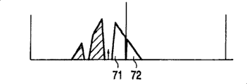
Fig. 7 has shown the frequency spectrum after utilizing filter 4 filtering.Because stereophonic difference signal L-R is with the inclined-plane value filtering in the inclined-plane 69, depend on relevant inclined-plane value, be that the L-R signal obtains the value that reduces.Connecting coherent signal that sideband 71 with minimizing and 72 are provided on 28 and it is being provided to modulator 5.
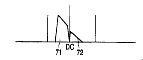
Fig. 8 has shown in modulator 5 at the 19kHz place by the frequency spectrum of the multiple modulation and the 19kHz that moves to right.When the frequency of multiple modulation was the accurate multiple of original pilot tone, current pilot was positioned at the zero crossing place.In the 2 sampling filters 6 that descend, signal is lowered by 2 samplings.Complex signal is from connecting 30 by two different branch road transmission.In a branch road, signal is provided to filter circuit 7 being used for Audio Processing, and in another branch road, it is provided to elliptic filter 16, promptly has the band pass filter of little bandwidth, to be used to extract pilot tone 58 and 62.Pilot tone 58 near DC is used to control DCO 19 now, these DCO 19 control multiple modulation.
Fig. 9 has shown the signal in the filter circuit 7.Shown FIR filter 8 in left part, and shown FIR filter 9 with frequency response 74 in the right side part with frequency response 73.Filter circuit is the FIR high pass and the low pass filter of symmetry of (Fs/2)/4=22.05kHz that move to left, so that separate L+R and L-R signal.
Figure 10 has shown by FIR low pass filter 8 at the frequency spectrum that the output signal that provides on 32 is provided.This signal is the L+R monophonic signal with inclined-plane 66 complex filters, has the sideband 67 and 68 of two minimizings.
Figure 11 has shown by FIR filter 9 at the frequency spectrum that the output signal that provides on 31 is provided.This signal is the L-R stereophonic difference signal with inclined-plane 69 complex filters, has the sideband 71 and 72 of two minimizings.
Figure 12 has shown the frequency spectrum after low pass filter 16.Pilot tone 58 is at the DC place.
Figure 13 has shown the frequency spectrum of the L+R monophonic signal after modulator 10.In modulator 10, signal is modulated with 19kHz, the 19kHz that promptly moves to right, thus make that the sideband 67 and 68 of two minimizings of frequency spectrum is the center with DC.
Figure 14 has shown the frequency spectrum of the L-R difference signal after modulator 11.In modulator 11, the L-R signal promptly moves to left-19kHz with-19kHz modulation, thereby makes that the sideband 71 and 72 of two minimizings of frequency spectrum is the center with DC.
Figure 15 has shown the frequency spectrum of the L-R signal with original sideband 66 and 76 after transducer 14.Transducer 14 filters real part from plural L+R signal, thereby obtains original L+R signal.
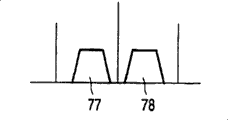
Figure 16 has shown the frequency spectrum of the L-R signal with original sideband 77 and 78 after transducer 15.Transducer 15 filters real part from plural L-R signal, thereby obtains original L-R signal.
Figure 17 has shown phase-locked loop or PLL 80, and it has modulator 3, FIR filter 4, second modulator 5,2 sampling filters 6, oval low pass filter 16, control access 17, interpolation filter 18, DCO 19 and delay element 20 descend.Control access 17 comprises amplifier 81 with coefficient a, the delay element 82 in forward direction control 84 and has second amplifier 83 of coefficient b and the delay element in FEEDBACK CONTROL 86 85 and two adders 87 and 88.PLL 80 operates according to following manner.
When DCO 19 with pilot tone during with frequency and Phase synchronization timing, original L-R signal can only accurately recover and with L+R signal homophase.This means that complex signal only has the DC part after oval low pass filter 16, perhaps the imaginary part of signal is zero.Utilize PLL 80, be used to control DCO 19 with zero deviation and make itself and pilot phase synchronous.
When the side-play amount that begins from initial phase and frequency departure was set to zero, ratio and integral control path 16 were essential, thereby made in phase place and frequency it all is zero synchronous in input signal and the side-play amount of segmentation.
After multiple modulation, have only imaginary part, promptly in fact have only phase identification to be used in the feedback loop of PLL, and be used to control DCO 19.
The characteristic of transient response, for example response time and decay can be adjusted by the multiplication constant a of the amplifier in the control access 17 81 and 83 and the adjustment of b.
The input signal of oscillator 19 is to the unmatched correction between the output signal of the phase place of pilot tone and DCO 19.
Figure 18 has shown the DCO 19 with 90,91,92 and 93, two delay elements 94 of four operational amplifiers and 95 and two adders 96 and 97.Plural number oscillator 19 produces cosine signal at first output, 98 places, and produces sinusoidal signal at second output, 99 places.The coefficient s of operational amplifier 90 and 92 coefficient c and operational amplifier 91 and 93 and-s can be by following calculating:
c=cos(2πθ/Fs)
s=sin(2πθ/Fs)
Original value in the delay circuit 94 and 95 should be set to 0 and 1.Output signal as the control access of unmatched correction is used to revise coefficient c and s by linear Taylor sequence, and wherein ε n is the output signal of control access 17, and it controls DCO 19:
c=cos(2πθ/Fs)-sin(2πθ/Fs)*∑∈n
s=sin(2πθ/Fs)+cos(2πθ/Fs)*∑∈n
Plural oscillator 19 with frequency of oscillation θ may form with software, as the stable oscillation filter of boundary.
Reference numerals list:
1 stereodecoder
The 2FIR wave filter
3 complex modulator
4 the 2nd FIR wave filters
5 complex modulator
6 declines, 2 sampling wave filters
7 filter circuits
8,9FIR wave filter
10,11 complex modulator
12,13 declines, 2 sampling wave filters
14,15 converters
16 low pass filters
17 control access
18 interpolation filters
19 oscillators
20 delay elements
21 declines, 2 sampling wave filters
22 second delay elements
23 declines, 2 sampling wave filters
24 the 3rd delay elements
25,26,27,28,29,30,31 32,33,34,35,36 signals connect
37,38 outputs
39,40,41 signals connect
42,43,44,45,46,47 connect
48 inputs
49 tuners
50 antennas
51 frequency demodulators
The 52A/D transducer
53 connect
54 transducers
55,56 loud speakers
The 57L+R signal
58 pilot tones
59L-R signal first sideband
60L-R signal second sideband
The L+R signal of 61 sides counter-rotating
62 pilot tones, the side counter-rotating
63L-R signal first frequency band, the side counter-rotating
64L-R signal second frequency band, the side counter-rotating
65 frequency responses
66 inclined-planes
The 67L+R sideband, minimizing
68 the 2nd L+R sidebands, minimizing
69 second inclined-planes
The response of 70 second frequencies
The 71L-R sideband, minimizing
72 L-R sidebands, minimizing
73,74 frequency responses
75,76 real number L+R sidebands
77,78 real number L-R sidebands
79
80 phase-locked loops
81 amplifiers
82 delay elements
83 amplifiers
The control of 84 forward directions
85 delay elements
86 feedbacks
87,88 adders
89
90,91,92,93 operational amplifiers
94,95 delay elements
96,97 adders
98,99 outputs