CN100412406C - Adjacent baffle design for shock absorber - Google Patents
Adjacent baffle design for shock absorber Download PDFInfo
- Publication number
- CN100412406C CN100412406C CNB2004800314963A CN200480031496A CN100412406C CN 100412406 C CN100412406 C CN 100412406C CN B2004800314963 A CNB2004800314963 A CN B2004800314963A CN 200480031496 A CN200480031496 A CN 200480031496A CN 100412406 C CN100412406 C CN 100412406C
- Authority
- CN
- China
- Prior art keywords
- vibration damper
- guide plate
- damper according
- oil storage
- pressure cylinder
- Prior art date
- Legal status (The legal status is an assumption and is not a legal conclusion. Google has not performed a legal analysis and makes no representation as to the accuracy of the status listed.)
- Expired - Fee Related
Links
- 239000006096 absorbing agent Substances 0.000 title abstract description 6
- 230000035939 shock Effects 0.000 title abstract description 6
- 238000013461 design Methods 0.000 title description 4
- 239000006071 cream Substances 0.000 claims description 25
- 239000013013 elastic material Substances 0.000 claims 3
- 230000009977 dual effect Effects 0.000 abstract 1
- 239000012530 fluid Substances 0.000 description 47
- 230000006835 compression Effects 0.000 description 23
- 238000007906 compression Methods 0.000 description 23
- 238000013016 damping Methods 0.000 description 18
- 238000000034 method Methods 0.000 description 15
- 239000000725 suspension Substances 0.000 description 12
- 238000007789 sealing Methods 0.000 description 6
- 230000003321 amplification Effects 0.000 description 4
- 238000012937 correction Methods 0.000 description 4
- 238000003199 nucleic acid amplification method Methods 0.000 description 4
- 238000012546 transfer Methods 0.000 description 4
- 230000000712 assembly Effects 0.000 description 3
- 238000000429 assembly Methods 0.000 description 3
- 238000012423 maintenance Methods 0.000 description 2
- 230000036316 preload Effects 0.000 description 2
- 239000007787 solid Substances 0.000 description 2
- 241000153246 Anteros Species 0.000 description 1
- 238000005273 aeration Methods 0.000 description 1
- 238000005516 engineering process Methods 0.000 description 1
- 230000036039 immunity Effects 0.000 description 1
- 230000001105 regulatory effect Effects 0.000 description 1
- 230000007306 turnover Effects 0.000 description 1
Images


Classifications
-
- F—MECHANICAL ENGINEERING; LIGHTING; HEATING; WEAPONS; BLASTING
- F16—ENGINEERING ELEMENTS AND UNITS; GENERAL MEASURES FOR PRODUCING AND MAINTAINING EFFECTIVE FUNCTIONING OF MACHINES OR INSTALLATIONS; THERMAL INSULATION IN GENERAL
- F16F—SPRINGS; SHOCK-ABSORBERS; MEANS FOR DAMPING VIBRATION
- F16F9/00—Springs, vibration-dampers, shock-absorbers, or similarly-constructed movement-dampers using a fluid or the equivalent as damping medium
- F16F9/06—Springs, vibration-dampers, shock-absorbers, or similarly-constructed movement-dampers using a fluid or the equivalent as damping medium using both gas and liquid
- F16F9/062—Bi-tubular units
-
- F—MECHANICAL ENGINEERING; LIGHTING; HEATING; WEAPONS; BLASTING
- F16—ENGINEERING ELEMENTS AND UNITS; GENERAL MEASURES FOR PRODUCING AND MAINTAINING EFFECTIVE FUNCTIONING OF MACHINES OR INSTALLATIONS; THERMAL INSULATION IN GENERAL
- F16F—SPRINGS; SHOCK-ABSORBERS; MEANS FOR DAMPING VIBRATION
- F16F9/00—Springs, vibration-dampers, shock-absorbers, or similarly-constructed movement-dampers using a fluid or the equivalent as damping medium
- F16F9/32—Details
- F16F9/3207—Constructional features
- F16F9/3235—Constructional features of cylinders
- F16F9/3257—Constructional features of cylinders in twin-tube type devices
-
- F—MECHANICAL ENGINEERING; LIGHTING; HEATING; WEAPONS; BLASTING
- F16—ENGINEERING ELEMENTS AND UNITS; GENERAL MEASURES FOR PRODUCING AND MAINTAINING EFFECTIVE FUNCTIONING OF MACHINES OR INSTALLATIONS; THERMAL INSULATION IN GENERAL
- F16F—SPRINGS; SHOCK-ABSORBERS; MEANS FOR DAMPING VIBRATION
- F16F9/00—Springs, vibration-dampers, shock-absorbers, or similarly-constructed movement-dampers using a fluid or the equivalent as damping medium
- F16F9/32—Details
- F16F9/34—Special valve constructions; Shape or construction of throttling passages
- F16F9/348—Throttling passages in the form of annular discs or other plate-like elements which may or may not have a spring action, operating in opposite directions or singly, e.g. annular discs positioned on top of the valve or piston body
- F16F9/3485—Throttling passages in the form of annular discs or other plate-like elements which may or may not have a spring action, operating in opposite directions or singly, e.g. annular discs positioned on top of the valve or piston body characterised by features of supporting elements intended to guide or limit the movement of the annular discs
-
- F—MECHANICAL ENGINEERING; LIGHTING; HEATING; WEAPONS; BLASTING
- F16—ENGINEERING ELEMENTS AND UNITS; GENERAL MEASURES FOR PRODUCING AND MAINTAINING EFFECTIVE FUNCTIONING OF MACHINES OR INSTALLATIONS; THERMAL INSULATION IN GENERAL
- F16F—SPRINGS; SHOCK-ABSORBERS; MEANS FOR DAMPING VIBRATION
- F16F9/00—Springs, vibration-dampers, shock-absorbers, or similarly-constructed movement-dampers using a fluid or the equivalent as damping medium
- F16F9/32—Details
- F16F9/36—Special sealings, including sealings or guides for piston-rods
- F16F9/366—Special sealings, including sealings or guides for piston-rods functioning as guide only, e.g. bushings
Landscapes
- Engineering & Computer Science (AREA)
- General Engineering & Computer Science (AREA)
- Mechanical Engineering (AREA)
- Fluid-Damping Devices (AREA)
Abstract
A dual tube shock absorber includes a baffle located in the reservoir chamber to define a non-linear flow path within the reservoir chamber. The baffle extends between the pressure tube and the reservoir tube such that the non-linear flow path is the only flow path between two portions of the reservoir chamber. One embodiment is a T-shaped baffle, and another embodiment has a base section and an upright section with a wire being embedded in the base section.
Description
Technical field
Present invention relates in general to have the dual-tube shock absorber of the unique guide plate design that is positioned at shoe cream room.More particularly, the present invention relates to have the dual-tube shock absorber of the guide plate that is positioned at shoe cream room, the guide plate directing fluid flows to helical duct, to reduce the inflation of damping fluid.
Background technique
Vibration damper is used in combination with suspension system and other suspension system of automobile, to absorb the unwanted vibration that takes place in the suspension system movement process.In order to absorb these unwanted vibrations, the vibration damper of automobile is connected between the sprung weight (vehicle body) and unsprung weight (suspension) of automobile usually.
One of vehicle shock absorber of general type is a bitubular type vibration damper.These vibration dampers have the piston that is positioned at pressure cylinder.Piston typically uses piston rod to be connected to the sprung weight of vehicle.Piston is divided into active chamber and following active chamber with pressure cylinder.Because when vibration damper is upheld, piston has the ability that flows from the downward active chamber of last active chamber by damping fluid in the valve restriction pressure cylinder, so vibration damper can produce the damping force of offsetting vibration in the extension stroke process, otherwise vibration will be transferred to sprung weight from unsprung weight.In dual-tube shock absorber, shoe cream room is limited at pressure cylinder and centers between the oil storage cylinder of pressure cylinder setting.Bottom valve assembly is down between active chamber and the shoe cream room.Because when vibration damper compresses, bottom valve assembly has the ability that flows to shoe cream room from following active chamber by valve restriction damping fluid, so vibration damper can produce the damping force of offsetting vibration in the compression stroke process, otherwise vibration will be transferred to sprung weight from unsprung weight.
Only by last active chamber and extend because the piston rod of vibration damper, so piston causes the difference that goes up the Fluid Volume that shifts in the Fluid Volume that shifts in the active chamber and the following active chamber with respect to the motion of pressure cylinder by following active chamber.The difference of the Fluid Volume of this transfer is exactly known rod volume, and rod volume flows through bottom valve assembly in extension stroke and compression stroke process.
When vibration damper is upheld on length, i.e. extension stroke, fluid flows from the downward active chamber of last active chamber by the valve in the piston, producing damping force, but because the notion of rod volume, needs the Fluid Volume that adds in active chamber down.Therefore, fluid will flow from the downward active chamber of shoe cream room by the safety check that is positioned at bottom valve assembly.Safety check does not produce damping force.
When vibration damper compresses on length, i.e. compression stroke, fluid flows from the active chamber that makes progress of active chamber down by the safety check in the piston.Fluid by safety check does not produce damping force.Because the notion of rod volume, additional Fluid Volume must be removed from following active chamber.Therefore, fluid will be by the valve in the bottom valve assembly from active chamber be mobile to shoe cream room down, to produce damping force.
In some applications, fluid is by the continuous inflow of bottom valve assembly with flow out the inflation that shoe cream room has caused damping fluid.In order to reduce the inflation of damping fluid, the guide plate spring has been designed to shoe cream room.The guide plate spring of these prior aries typically forms helical spring, and helical spring is arranged on the pressure cylinder, extending to oil storage cylinder, but does not extend to pressure cylinder.Therefore, between guide plate spring and oil storage cylinder, reserve opening.
Although in some applications, the design of these guide plate springs is proved to be the amount that can reduce inflation, but the mobile possibility that uncontrollable damping fluid is still arranged between guide plate spring and oil storage cylinder, it has enlarged oil-gas meter face, and has therefore worsened the immunity of inflation.
Summary of the invention
The invention provides the technology of guide plate spring, the guide plate spring is crossed over the whole width of oil storage cylinder.Therefore, guide plate spring contact pressure cylinder and oil storage cylinder are to limit the helical duct that fluid flows.
In the detailed description that provides from below, the more areas that the present invention uses will become obvious.Should be appreciated that, though detailed description and specific example are indicated preferred embodiment of the present invention, only be purpose with exemplary, and never intention limits the scope of the invention.
Description of drawings
From detailed description and drawings, the present invention will be understood more all sidedly, wherein:
Fig. 1 contains the schematic presentation that comprises according to the typical automotive of the vibration damper of unique guide plate spring of the present invention;
Fig. 2 is the sectional view according to vibration damper of the present invention;
Fig. 3 is the amplification sectional view according to piston assembly of the present invention;
Fig. 4 is the amplification sectional view according to bottom valve assembly of the present invention;
Fig. 5 is the amplification sectional view according to the guide plate spring between pressure cylinder and oil storage cylinder of the present invention; With
But Fig. 6 is similar in appearance to Fig. 3 the amplification sectional view of the guide plate spring between pressure cylinder and oil storage cylinder according to another embodiment of the present invention.
Embodiment
The description of following preferred embodiment only is exemplary in essence, and never intention restriction the present invention, its application or use.
Referring now to accompanying drawing, wherein in whole accompanying drawing, the identical identical or corresponding part of reference character indication contains the vehicle that comprises according to the suspension system of vibration damper of the present invention shown in Fig. 1, and vehicle is generally by reference character 10 indications.Vehicle 10 comprises rear suspension 12, front suspension 14 and vehicle body 16.Rear suspension 12 have horizontal expansion, be suitable for the operationally rear axle assemblies (not shown) of the pair of rear wheels 18 of support vehicle 10.Rear axle assemblies is operably connected to vehicle body 16 by a pair of vibration damper 20 and a pair of helical spring 22.Similarly, front suspension 14 comprise horizontal expansion, the preceding shaft assembly (not shown) of a pair of front-wheel 24 of support vehicle 10 operationally.Preceding shaft assembly is operably connected to vehicle body 16 by a pair of vibration damper 26 and a pair of helical spring 28. Vibration damper 20 and 26 is as the unsprung weight (being front suspension 12 and rear suspension 14) that suppresses vehicle 10 and the relative movement of sprung weight (being vehicle body 16).Though vehicle 10 is depicted as the passenger vehicle with antero posterior axis assembly, vibration damper 20 and 26 can be used for the vehicle of other type or the application of other type, for example comprises the vehicle of independently preceding and/or independent rear-suspension system.Further, " vibration damper " used herein this speech means the damper on the indication ordinary meaning, therefore comprises the Mai Fuxun pillar.
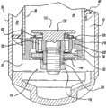
Referring now to Fig. 2,, illustrates in greater detail vibration damper 20.Though Fig. 2 only illustrates vibration damper 20, should be appreciated that vibration damper 26 also comprises the bottom valve assembly that is used for vibration damper 20 described below.Vibration damper 26 only is suitable for being connected on the spring of vehicle 10 and on the mode of unsprung weight at it and is different from vibration damper 20.Vibration damper 20 comprises the guide plate of pressure cylinder 30, piston assembly 32, piston rod 34, oil storage cylinder 36, bottom valve assembly 38 and guide plate spring 40 forms.
Referring now to Fig. 3,, piston assembly 32 comprises piston body 60, compression valve assembly 62 and resilience valve assembly 64.Compression valve assembly 62 assembles against the shoulder 66 on the piston rod 34.Piston body 60 is against 62 assemblings of compression valve assembly, and resilience valve assembly 64 is against piston body 60 assemblings.Nut 68 is fixed on these parts on the piston rod 34.
Piston body 60 limits a plurality of pressure channels 70 and a plurality of rebound channel 72.Sealing 48 comprises a plurality of ribs 74 that closely cooperate and slide with permission piston assembly 32 with a plurality of circular grooves 76.
In the rebound stroke process, the fluid in the last active chamber 44 is pressurized, causes the hydrodynamic pressure that acts on valve disc 86.When the hydrodynamic pressure that acts on valve disc 86 overcame the flexural load of valve disc 86, rebound channel 72 was opened in flexibly deflection of valve disc 86, allowed fluid to flow from last active chamber 44 downward active chambers 46.The size of the intensity of valve disc 86 and rebound channel 72 will be determined the damping characteristic in vibration damper 20 resiliences.When the hydrodynamic pressure in the last active chamber 44 reaches predeterminated level, hydrodynamic pressure will overcome the offset placed load of belleville spring 90, cause the axial motion of retainer 88 and a plurality of valve disc 86.Rebound channel 72 is opened in the axial motion of retainer 88 and valve disc 86 fully, therefore allows a large amount of damping fluids to pass through, and produces the release of hydrodynamic pressure, and the release of hydrodynamic pressure is required for avoiding the damage to vibration damper 20 and/or vehicle 10.
Referring now to Fig. 4,, bottom valve assembly 38 comprises valve body 110, resilience valve assembly 112, compression valve assembly 114 and bolt 116.Resilience valve assembly 112 is against the head assembling of bolt 116.Valve body 110 is against 112 assemblings of resilience valve assembly, and compression valve assembly 114 is against valve body 110 assemblings.Nut 118 is fixed on these parts on the bolt 116.
In the compression stroke process, the fluid in the following active chamber 46 is pressurized, causes the hydrodynamic pressure that acts on valve disc 136.When the hydrodynamic pressure that acts on valve disc 136 overcame the flexural load of valve disc 136, valve disc 136 elastic deflections to open pressure channel 122, allowed fluid from active chamber 46 is mobile to shoe cream room 52 down.Fluid also flows to active chamber 44 by the compression valve assembly 62 in the piston assembly 32 from following active chamber 46.Because the notion of " rod volume " takes place by the fluid of compression valve assembly 114 is mobile.The size of the intensity of valve disc 136 and pressure channel 122 will be determined the damping characteristic of vibration damper 20 in compression.When the hydrodynamic pressure in the active chamber 46 reaches predeterminated level instantly, hydrodynamic pressure will overcome the offset placed load of belleville spring 140, cause the axial motion of retainer 138 and a plurality of valve disc 136.Pressure channel 122 is opened in the axial motion of retainer 138 and valve disc 136 fully, therefore allows a large amount of damping fluids to pass through, and produces the release of hydrodynamic pressure, and the release of hydrodynamic pressure is required for avoiding the damage to vibration damper 20 and/or vehicle 10.
In some applications, the motion of fluid turnover shoe cream room 52 causes the inflation of hydraulic fluid.The aeration quantity of each application is different from the highstrung application-specific of inflation problem.For these application extremely responsive, have been found that the performance of prior art guide plate spring is inadequate to inflation.
Referring now to Fig. 6,, illustrates guide plate spring 240 according to another embodiment of the present invention.Guide plate spring 240 comprises having base part 242 that is arranged on the wire 244 in the base part 242 and the vertical component 246 that extends with joint oil storage cylinder 36 from base part 240.Guide plate spring 240 is elasticity or rubber molds of being reinforced by wire 244.Guide plate 240 spiralitys ground centers on pressure cylinder 30, and utilizes the elastic force of wire 244 to engage with pressure cylinder 30.The height of vertical component 246 makes guide plate spring 240 big a little with respect to the internal diameter of oil storage cylinder 36.Guide plate spring 240 guarantees that with respect to oil storage cylinder 36 excessive sizes guide plate spring 240 fully engages between pressure cylinder 30 and oil storage cylinder 36.
Guide plate spring 240 forces the fluid in the shoe cream room 52 to flow and follows helical duct, and helical duct is formed by the interval that produces between guide plate spring 240, pressure cylinder 30 and the oil storage cylinder 36.Guide plate spring 240 provides abundant tightness between guide plate spring 240 and cylinder 30 and 36 with respect to the excessive character of oil storage cylinder 36 internal diameters.Although be illustrated to form helical duct between guide plate spring 40, pressure cylinder 30 and oil storage cylinder 36 at this, the shape of passage is not limited to this.The passage that forms between guide plate spring 40, pressure cylinder 30 and oil storage cylinder 36 can be any non-linear shape, as long as it forms unique fluid flowing passage.
Description of the invention only is exemplary in essence, and the change that does not therefore break away from main points of the present invention will be in the scope of the present invention.The disengaging the spirit and scope of the present invention are not thought in such change.
Claims (19)
1. vibration damper comprises:
Limit the pressure cylinder of active chamber;
Be slidably disposed on the piston body in the described active chamber, described piston body is divided into active chamber and following active chamber with described active chamber;
Be connected to the piston rod of described piston body, the end that described piston rod passes described pressure cylinder extends;
Oil storage cylinder around described pressure cylinder forms shoe cream room between described oil storage cylinder and the described pressure cylinder;
Be arranged on the bottom valve assembly between described active chamber and the described shoe cream room; With
Be arranged on the guide plate in the described shoe cream room, described guide plate limits the non-linear mobile passage between the second portion of the first portion of described shoe cream room and described shoe cream room, and described non-linear mobile passage is the unique flow channel between described first and second parts of described shoe cream room.
2. vibration damper according to claim 1, the contiguous described bottom valve assembly of the described first portion of wherein said non-linear mobile passage.
3. vibration damper according to claim 1, wherein said guide plate comprises the guide plate spring.
4. vibration damper according to claim 3, wherein said guide plate spring engages described pressure cylinder and described oil storage cylinder.
5. vibration damper according to claim 1, wherein said guide plate has T section.
6. vibration damper according to claim 5, wherein said T section comprise base part that engages described pressure cylinder and the vertical component that engages described oil storage cylinder.
7. vibration damper according to claim 5, wherein said guide plate comprises elastic material.
8. vibration damper according to claim 1, wherein said guide plate comprises base part and vertical component.
9. vibration damper according to claim 8, wherein said guide plate comprise the wire that is arranged in the described base part.
10. vibration damper according to claim 8, wherein said base part engages described pressure cylinder, and described vertical component engages described oil storage cylinder.
11. vibration damper according to claim 8, wherein said guide plate comprises elastic material.
12. vibration damper according to claim 1, wherein said guide plate engage described pressure cylinder and described oil storage cylinder.
13. vibration damper according to claim 1, wherein said guide plate comprises elastic material.
14. vibration damper according to claim 1, wherein said non-linear mobile passage is spiral flow channel.
15. vibration damper according to claim 14, wherein said guide plate has T section.
16. vibration damper according to claim 15, wherein said T section comprise base part that engages described pressure cylinder and the vertical component that engages described oil storage cylinder.
17. vibration damper according to claim 14, wherein said guide plate comprises base part and vertical component.
18. vibration damper according to claim 17, wherein said guide plate comprise the wire that is arranged in the described base part.
19. vibration damper according to claim 17, wherein said base part engages described pressure cylinder, and described vertical component engages described oil storage cylinder.
Applications Claiming Priority (2)
| Application Number | Priority Date | Filing Date | Title |
|---|---|---|---|
| US10/674,025 | 2003-09-29 | ||
| US10/674,025 US6913127B2 (en) | 2003-09-29 | 2003-09-29 | Adjacent baffle design for shock absorber |
Publications (2)
| Publication Number | Publication Date |
|---|---|
| CN1871451A CN1871451A (en) | 2006-11-29 |
| CN100412406C true CN100412406C (en) | 2008-08-20 |
Family
ID=34376773
Family Applications (1)
| Application Number | Title | Priority Date | Filing Date |
|---|---|---|---|
| CNB2004800314963A Expired - Fee Related CN100412406C (en) | 2003-09-29 | 2004-09-15 | Adjacent baffle design for shock absorber |
Country Status (6)
| Country | Link |
|---|---|
| US (1) | US6913127B2 (en) |
| CN (1) | CN100412406C (en) |
| BR (1) | BRPI0414833A (en) |
| DE (1) | DE112004001835T5 (en) |
| GB (1) | GB2421292B (en) |
| WO (1) | WO2005033545A1 (en) |
Families Citing this family (19)
| Publication number | Priority date | Publication date | Assignee | Title |
|---|---|---|---|---|
| US10900539B2 (en) | 2005-12-30 | 2021-01-26 | Fox Factory, Inc. | Fluid damper having a damping profile favorable for absorbing the full range of compression forces, including low- and high-speed compression forces |
| US20070278028A1 (en) * | 2006-06-05 | 2007-12-06 | Wayne Robert Fought | Anti-aeration system for a suspension actuator |
| US8627933B2 (en) * | 2010-06-01 | 2014-01-14 | Tenneco Automotive Operating Company Inc. | Two stage valve and hydraulic damped valve |
| WO2012054774A2 (en) | 2010-10-20 | 2012-04-26 | Penske Racing Shocks | Shock absorber with inertance |
| CN103032509B (en) * | 2011-09-29 | 2015-08-26 | 上海汽车集团股份有限公司 | Oil-leakage-prevention double barreled fluid power snubber for car |
| JP5519822B2 (en) * | 2012-06-28 | 2014-06-11 | 株式会社ショーワ | Hydraulic shock absorber |
| JP2016528458A (en) * | 2013-08-14 | 2016-09-15 | テネコ オートモティブ オペレーティング カンパニー インコーポレイテッドTenneco Automotive Operating Company Inc. | Low pressure, high compression damping monotube shock absorber |
| CN104565169A (en) * | 2013-10-18 | 2015-04-29 | 丹阳市米可汽车零部件厂 | Damper |
| US9377076B2 (en) * | 2015-02-16 | 2016-06-28 | Caterpillar Inc. | Magneto-rheological damping system for preventing stratification |
| CA3005667C (en) * | 2015-12-01 | 2020-07-14 | Hendrickson Usa, L.L.C. | Damping air spring with staged openings |
| KR102066366B1 (en) * | 2016-02-24 | 2020-01-14 | 히다치 오토모티브 시스템즈 가부시키가이샤 | Cylinder device and its manufacturing method |
| US11007834B2 (en) | 2016-12-15 | 2021-05-18 | Tenneco Automotive Operating Company Inc. | Baffle tube for damper with electromechanical valve |
| US10054182B2 (en) | 2016-12-15 | 2018-08-21 | Tenneco Automotive Operating Company Inc. | Baffle tube for damper with electromechanical valve |
| US11383571B2 (en) * | 2017-01-09 | 2022-07-12 | Ford Global Technologies, Llc | Shock absorbers having internal jounce control |
| JP6216899B1 (en) * | 2017-03-03 | 2017-10-18 | 株式会社ショーワ | Pressure shock absorber |
| US10987988B2 (en) | 2017-06-28 | 2021-04-27 | Tenneco Automotive Operating Company Inc. | Damper with volume reducing insert |
| US10704641B2 (en) | 2017-12-15 | 2020-07-07 | Tenneco Automotive Operating Company Inc. | Baffle for damper with electromechanical valve |
| US10837515B2 (en) | 2019-02-11 | 2020-11-17 | Tenneco Automotive Operating Company Inc. | Damper baffle tube with elastomeric skirt |
| FR3134038A1 (en) * | 2022-03-30 | 2023-10-06 | Psa Automobiles Sa | MOTOR VEHICLE COMPRISING A SHOCK ABSORBER HAVING AN INTEGRATED INERTIAL STOP |
Citations (6)
| Publication number | Priority date | Publication date | Assignee | Title |
|---|---|---|---|---|
| US2717669A (en) * | 1951-02-24 | 1955-09-13 | Girling Ltd | Shock absorber with reservoir baffle |
| US3225870A (en) * | 1963-10-21 | 1965-12-28 | Oldberg Mfg Company | Shock absorber baffle means |
| US3931961A (en) * | 1972-11-20 | 1976-01-13 | Monroe Belgium N.V. | Shock absorber |
| US3945474A (en) * | 1975-01-20 | 1976-03-23 | Monroe Auto Equipment Company | Shock absorber |
| US4742898A (en) * | 1986-09-17 | 1988-05-10 | Enidine Incorporated | Shock absorber with gas charged return spring |
| CN1113298A (en) * | 1994-02-22 | 1995-12-13 | 株式会社优尼希雅杰克斯 | Hydraulic shock absorber having variable damping force characteristic structure |
Family Cites Families (1)
| Publication number | Priority date | Publication date | Assignee | Title |
|---|---|---|---|---|
| US4440273A (en) * | 1981-12-28 | 1984-04-03 | Halliburton Company | Aeration preventing shock absorber |
-
2003
- 2003-09-29 US US10/674,025 patent/US6913127B2/en not_active Expired - Fee Related
-
2004
- 2004-09-15 BR BRPI0414833-9A patent/BRPI0414833A/en not_active IP Right Cessation
- 2004-09-15 CN CNB2004800314963A patent/CN100412406C/en not_active Expired - Fee Related
- 2004-09-15 DE DE112004001835T patent/DE112004001835T5/en not_active Withdrawn
- 2004-09-15 GB GB0606014A patent/GB2421292B/en not_active Expired - Fee Related
- 2004-09-15 WO PCT/US2004/030169 patent/WO2005033545A1/en active Application Filing
Patent Citations (6)
| Publication number | Priority date | Publication date | Assignee | Title |
|---|---|---|---|---|
| US2717669A (en) * | 1951-02-24 | 1955-09-13 | Girling Ltd | Shock absorber with reservoir baffle |
| US3225870A (en) * | 1963-10-21 | 1965-12-28 | Oldberg Mfg Company | Shock absorber baffle means |
| US3931961A (en) * | 1972-11-20 | 1976-01-13 | Monroe Belgium N.V. | Shock absorber |
| US3945474A (en) * | 1975-01-20 | 1976-03-23 | Monroe Auto Equipment Company | Shock absorber |
| US4742898A (en) * | 1986-09-17 | 1988-05-10 | Enidine Incorporated | Shock absorber with gas charged return spring |
| CN1113298A (en) * | 1994-02-22 | 1995-12-13 | 株式会社优尼希雅杰克斯 | Hydraulic shock absorber having variable damping force characteristic structure |
Also Published As
| Publication number | Publication date |
|---|---|
| GB2421292B (en) | 2008-05-14 |
| WO2005033545A1 (en) | 2005-04-14 |
| DE112004001835T5 (en) | 2006-08-10 |
| US20050067240A1 (en) | 2005-03-31 |
| CN1871451A (en) | 2006-11-29 |
| GB2421292A (en) | 2006-06-21 |
| BRPI0414833A (en) | 2006-11-14 |
| US6913127B2 (en) | 2005-07-05 |
| GB0606014D0 (en) | 2006-05-03 |
Similar Documents
| Publication | Publication Date | Title |
|---|---|---|
| CN100412406C (en) | Adjacent baffle design for shock absorber | |
| CN103256335B (en) | Nested check high speed valve | |
| CN100422592C (en) | Extra support land for valve disc | |
| CN101809312B (en) | Disc spring intake | |
| CN1918400B (en) | Rod guide and seal system for gas filled shock absorbers | |
| US6981578B2 (en) | Non-pressurized monotube shock absorber | |
| CN102141104A (en) | Asymmetrical intake damper valve | |
| CN101657651B (en) | Shock absorber having a continuously variable valve with base line valving | |
| CN100422593C (en) | Extra support area for valve disc | |
| US9550403B2 (en) | Hydropneumatic suspension unit | |
| CN102648361A (en) | Velocity progressive valving | |
| CN101287926A (en) | Amplitude controlled orifice valving | |
| CN100526673C (en) | Compensated rod for a frequency dependent damper shock absorber | |
| CN103620257A (en) | Low noise valve assembly | |
| CN100465471C (en) | Air pressure proportional damper | |
| CN100494728C (en) | Heavy duty base valve | |
| CN101243266A (en) | Asymmetrical intake damper valve | |
| US20050051395A1 (en) | Fulcrum blow off valve for use in a shock absorber | |
| US6148969A (en) | Frequency dependant damper | |
| US6364075B1 (en) | Frequency dependent damper | |
| CN221610462U (en) | Air bag shock absorber for motorcycle | |
| GB2440014A (en) | A dual tube shock absorber baffle |
Legal Events
| Date | Code | Title | Description |
|---|---|---|---|
| C06 | Publication | ||
| PB01 | Publication | ||
| C10 | Entry into substantive examination | ||
| SE01 | Entry into force of request for substantive examination | ||
| C14 | Grant of patent or utility model | ||
| GR01 | Patent grant | ||
| CF01 | Termination of patent right due to non-payment of annual fee |
Granted publication date: 20080820 Termination date: 20140915 |
|
| EXPY | Termination of patent right or utility model |