CN100407612C - Method and device for turbo space-time grid coding - Google Patents
Method and device for turbo space-time grid coding Download PDFInfo
- Publication number
- CN100407612C CN100407612C CN008201234A CN00820123A CN100407612C CN 100407612 C CN100407612 C CN 100407612C CN 008201234 A CN008201234 A CN 008201234A CN 00820123 A CN00820123 A CN 00820123A CN 100407612 C CN100407612 C CN 100407612C
- Authority
- CN
- China
- Prior art keywords
- symbol
- encoder
- information
- output
- produces
- Prior art date
- Legal status (The legal status is an assumption and is not a legal conclusion. Google has not performed a legal analysis and makes no representation as to the accuracy of the status listed.)
- Expired - Lifetime
Links
- 238000000034 method Methods 0.000 title claims description 40
- 238000013507 mapping Methods 0.000 claims description 64
- 239000013598 vector Substances 0.000 claims description 26
- 230000005540 biological transmission Effects 0.000 claims description 7
- 230000009897 systematic effect Effects 0.000 abstract description 37
- 239000011159 matrix material Substances 0.000 description 22
- 238000004891 communication Methods 0.000 description 13
- 230000008569 process Effects 0.000 description 4
- 238000005562 fading Methods 0.000 description 3
- 238000013459 approach Methods 0.000 description 2
- 230000001413 cellular effect Effects 0.000 description 2
- 239000002131 composite material Substances 0.000 description 2
- 230000006872 improvement Effects 0.000 description 2
- 239000000203 mixture Substances 0.000 description 2
- 239000000654 additive Substances 0.000 description 1
- 230000000996 additive effect Effects 0.000 description 1
- 238000010276 construction Methods 0.000 description 1
- 230000003111 delayed effect Effects 0.000 description 1
- 230000000694 effects Effects 0.000 description 1
- 238000009472 formulation Methods 0.000 description 1
- 238000012986 modification Methods 0.000 description 1
- 230000004048 modification Effects 0.000 description 1
- 230000010363 phase shift Effects 0.000 description 1
- 230000010287 polarization Effects 0.000 description 1
- 238000013138 pruning Methods 0.000 description 1
- 238000004088 simulation Methods 0.000 description 1
Images


Classifications
-
- H—ELECTRICITY
- H04—ELECTRIC COMMUNICATION TECHNIQUE
- H04L—TRANSMISSION OF DIGITAL INFORMATION, e.g. TELEGRAPHIC COMMUNICATION
- H04L1/00—Arrangements for detecting or preventing errors in the information received
- H04L1/02—Arrangements for detecting or preventing errors in the information received by diversity reception
- H04L1/06—Arrangements for detecting or preventing errors in the information received by diversity reception using space diversity
- H04L1/0618—Space-time coding
- H04L1/0637—Properties of the code
- H04L1/065—Properties of the code by means of convolutional encoding
-
- H—ELECTRICITY
- H04—ELECTRIC COMMUNICATION TECHNIQUE
- H04L—TRANSMISSION OF DIGITAL INFORMATION, e.g. TELEGRAPHIC COMMUNICATION
- H04L1/00—Arrangements for detecting or preventing errors in the information received
- H04L1/004—Arrangements for detecting or preventing errors in the information received by using forward error control
- H04L1/0045—Arrangements at the receiver end
- H04L1/0047—Decoding adapted to other signal detection operation
- H04L1/005—Iterative decoding, including iteration between signal detection and decoding operation
-
- H—ELECTRICITY
- H04—ELECTRIC COMMUNICATION TECHNIQUE
- H04L—TRANSMISSION OF DIGITAL INFORMATION, e.g. TELEGRAPHIC COMMUNICATION
- H04L1/00—Arrangements for detecting or preventing errors in the information received
- H04L1/004—Arrangements for detecting or preventing errors in the information received by using forward error control
- H04L1/0056—Systems characterized by the type of code used
- H04L1/0059—Convolutional codes
- H04L1/006—Trellis-coded modulation
-
- H—ELECTRICITY
- H04—ELECTRIC COMMUNICATION TECHNIQUE
- H04L—TRANSMISSION OF DIGITAL INFORMATION, e.g. TELEGRAPHIC COMMUNICATION
- H04L1/00—Arrangements for detecting or preventing errors in the information received
- H04L1/004—Arrangements for detecting or preventing errors in the information received by using forward error control
- H04L1/0056—Systems characterized by the type of code used
- H04L1/0064—Concatenated codes
- H04L1/0066—Parallel concatenated codes
Landscapes
- Engineering & Computer Science (AREA)
- Computer Networks & Wireless Communication (AREA)
- Signal Processing (AREA)
- Error Detection And Correction (AREA)
- Radio Transmission System (AREA)
- Digital Transmission Methods That Use Modulated Carrier Waves (AREA)
Abstract
为采用多个发射天线(16、18)的时空分集提供一种特播编码装置,其中包括两个递归系统卷积编码器(30、32),向其中之一直接提供输入比特,向另一个提供在相应符号间隔中比特分组的交织(34)之后的信息比特。编码器所产生且包含系统和奇偶校验信息的符号在连续符号间隔中交替地提供给到天线的通路,以便提供时空分集。对于2和4个天线以及各种卷积码说明了一些装置,并且还说明了一种迭代解码器。

A turbo encoding apparatus is provided for space-time diversity using multiple transmit antennas (16, 18), comprising two recursive systematic convolutional encoders (30, 32), one of which provides input bits directly and the other Information bits are provided after interleaving (34) of groups of bits in corresponding symbol intervals. The symbols generated by the encoder and containing systematic and parity information are alternately provided to the path to the antenna during successive symbol intervals in order to provide space-time diversity. Arrangements are described for 2 and 4 antennas and various convolutional codes, and an iterative decoder is also described.
Description
本发明涉及采用通常所说的特播时空(ST)以及格形编码(TC)或格形编码调制(TCM)技术的组合的例如蜂窝无线通信系统的通信。The present invention relates to communications in, for example, cellular radio communication systems employing a combination of so-called Turbo Space-Time (ST) and Trellis Coding (TC) or Trellis Code Modulation (TCM) techniques.
发明背景Background of the invention
众所周知,无线通信信道易受时变多径衰落的影响,并且比较难以提高多径衰落信道的质量或降低其有效误码率。虽然已知用于减小多径衰落影响的各种技术,但其中的若干种(例如提高发射机功率或带宽)往往与无线通信系统的其它要求矛盾。已经发现的一种有利技术是天线分集,它在系统的发射机上和/或在接收机上采用两个或两个以上天线(或信号极化)。It is well known that wireless communication channels are susceptible to time-varying multipath fading, and it is difficult to improve the quality of multipath fading channels or reduce their effective bit error rate. While various techniques are known for reducing the effects of multipath fading, several of them (such as increasing transmitter power or bandwidth) often conflict with other requirements of a wireless communication system. One technique that has been found to be advantageous is antenna diversity, which employs two or more antennas (or signal polarizations) at the transmitter and/or at the receiver of the system.
在蜂窝无线通信系统中,各基站通常为多个远程(固定或移动)装置提供服务,其特征(例如大小和位置)更有利于天线分集,所以希望在至少一个基站上实现天线分集,而在远程装置上具有或没有天线分集。在这种情况下,至少对于来自基站的通信,这产生发射分集,即信号从两个或两个以上发射天线发出。In a cellular wireless communication system, each base station usually provides services for multiple remote (fixed or mobile) devices, and its characteristics (such as size and location) are more conducive to antenna diversity, so it is desirable to achieve antenna diversity on at least one base station, while in With or without antenna diversity on the remote unit. In this case, at least for communications from the base station, this results in transmit diversity, ie signals are sent from two or more transmit antennas.
S.M.Alamouti的“用于无线通信的简单发射分集技术”(IEEEJournal on Selected Areas in Communications,第16卷,第8期,第1451-1458页,1998年10月)描述了采用时空分组编码(STBC)的简单发射分集方案。对于两个发射天线的情况,复合符号s0和-s1*从一个天线依次发出,同时复合符号s1和s0*从另一天线依次发出,其中*表示复共轭。这些发射符号构成通常所说的时空码组。"Simple Transmit Diversity Techniques for Wireless Communications" by SM Alamouti (IEEE Journal on Selected Areas in Communications, Vol. 16, No. 8, pp. 1451-1458, October 1998) describes the use of space-time block coding (STBC) Simple transmit diversity scheme. For the case of two transmitting antennas, the composite symbols s0 and -s1 * are sent sequentially from one antenna, while the composite symbols s1 and s0 * are sent sequentially from the other antenna, where * denotes the complex conjugate. These transmitted symbols form what is commonly referred to as a space-time code group.
同样已知的还有使用各种编码方案以增强通信。在这些方案中,已认识到,通常所说的特播编码(并行级联卷积编码)使迭代解码方法能够获得接近AWGN(加性高斯白噪声)通信信道的香农极限的结果。特播编码器采用通常相同的两个递归系统卷积(RSC)分量编码器,待发送信号直接提供给分量编码器之一,并经由交织器提供给另一个分量编码器。因此,通常希望将特播和时空编码技术结合在同一发射机中。It is also known to use various encoding schemes to enhance communication. Among these schemes, it has been recognized that so-called turbo coding (parallel concatenated convolutional coding) enables iterative decoding methods to obtain results close to the Shannon limit of AWGN (Additive White Gaussian Noise) communication channels. The turbo encoder uses usually the same two Recursive Systematic Convolution (RSC) component encoders, and the signal to be transmitted is directly supplied to one of the component encoders and via an interleaver to the other component encoder. Therefore, it is often desirable to combine turbo and space-time coding techniques in the same transmitter.
V.Tarokh等人的“用于高数据速率无线通信的时空编码:性能标准和代码结构”(IEEE Transactions on Information Theory,第44卷,第2期,第744-765页,1998年3月)描述了各种卷积码或格码,它们可与两个或两个以上发射天线配合使用,以便提供格形(卷积)编码和时空编码的优势。虽然这些编码被认为对于最大分集增益是最佳的,但它们对于编码增益不一定是最佳的。此外,这些编码是非递归的。相反,已经证明采用递归编码获得特播编码的最佳效率。因此,Tarokh等人所述的编码不适用于特播编码方案。V. Tarokh et al., "Space-Time Coding for High Data Rate Wireless Communications: Performance Criteria and Code Structures" (IEEE Transactions on Information Theory, Vol. 44, No. 2, pp. 744-765, March 1998) Various convolutional or trellis codes are described that can be used with two or more transmit antennas to provide the advantages of trellis (convolutional) coding and space-time coding. Although these codes are considered optimal for maximum diversity gain, they are not necessarily optimal for coding gain. Also, these encodings are non-recursive. On the contrary, it has been proved that recursive coding is used to obtain the best efficiency of turbo coding. Therefore, the coding described by Tarokh et al. is not suitable for turbo coding schemes.
P.Robertson等人的“采用删截分量代码的带宽效率高的特播格形编码调制”(IEEE Journal on Selected Areas in Communications,第16卷,第2期,第206-218页,1998年2月)描述了采用Ungerboeck和多维TCM分量代码的特播编码器,其中,交织器对各m个信息比特的分组进行操作。对于与m个信息比特的分组对应的各个步骤,与各分量编码器相关的信号映射器产生n个符号,其中n=D/2,D为信号集维数;例如D=2或4,以及n=1或2。n-符号去交织器对来自第二分量编码器的输出符号进行去交织,选择器交替为相继步骤选择从第一分量编码器输出的符号以及来自去交织器的符号,并将其提供给单输出路径。这个方案没有提供发射分集,并且该文献未涉及到时空编码。"Bandwidth Efficient Turbo Trellis Coding Modulation Using Punctured Component Codes" by P.Robertson et al. 1) describes a turbo encoder employing Ungerboeck and multidimensional TCM component codes, where the interleaver operates on groups of m information bits each. For each step corresponding to the grouping of m information bits, the signal mapper associated with each component encoder produces n symbols, where n=D/2, D being the signal set dimension; for example D=2 or 4, and n=1 or 2. The n-symbol deinterleaver deinterleaves the output symbols from the second component encoder, and the selector alternately selects symbols output from the first component encoder and symbols from the deinterleaver for successive steps and provides them to the single output path. This scheme does not provide transmit diversity, and the document does not deal with space-time coding.
G.Bauch的“时空分组码的级联以及‘特播’-TCM”(Proceedings ofthe International Conference on Communications,ICC’99,第1202-1206页,1999年6月)描述了两种类型的特播格形编码调制(TCM)编码器,其输出提供给时空分组编码器,使特播-TCM和STBC方案只是彼此级联。这两种类型的特播TCM编码器之一如Robertson等人所述(对其进行了详细引用),如上所述,采用Ungerboeck编码并在映射功能的输出上提供一个符号,但Bauch对此进行的说明没有表明符号去交织器。Bauch的这个公开没有讨论多维分量编码。G. Bauch's "Concatenation of Time-Temporal Block Codes and 'Turbo'-TCM" (Proceedings of the International Conference on Communications, ICC'99, pp. 1202-1206, June 1999) describes two types of TCM A Trellis Coded Modulation (TCM) encoder whose output is fed to a space-time block encoder, so that Turbo-TCM and STBC schemes are simply concatenated with each other. One of these two types of turbo TCM encoders, described by Robertson et al. (which is cited in detail), above, employs Ungerboeck encoding and provides a symbol on the output of the mapping function, but Bauch's The description does not indicate a symbol deinterleaver. This publication by Bauch does not discuss multi-dimensional component coding.
还需要提供在无线通信中的进一步改善。There is also a need to provide further improvements in wireless communication.
发明概述Summary of the invention
根据一个方面,本发明提供一种为要从T个天线发送的信息提供时空分集的方法,包括以下步骤:在多个连续符号间隔的每一个中,在两个递归系统卷积编码器每一个的输出上产生包含系统信息和奇偶校验信息的T个符号,向编码器之一直接提供输入比特,以及在交织块中对各个符号间隔的比特分组进行交织之后向另一个编码器提供所述信息比特;以及选择第一和第二种不同的映射,在相应的交替符号间隔中,在编码器的输出上所产生的所述符号中的T个符号中的每一个用于提供给T个天线,以便提供所述时空分集,交织和映射经过设置,以便为交织块中的所有输入比特选择系统信息。According to one aspect, the present invention provides a method of providing space-time diversity for information to be transmitted from T antennas, comprising the steps of: in each of a plurality of consecutive symbol intervals, in each of two recursive systematic convolutional encoders T symbols containing systematic information and parity information are generated on the output of , and the input bits are directly provided to one of the encoders, and the other encoder is provided after interleaving the bit groups of each symbol interval in the interleaving block. information bits; and selecting first and second different mappings, in corresponding alternating symbol intervals, each of T of said symbols produced at the output of the encoder for supplying T Antennas to provide said space-time diversity, interleaving and mapping are set to select systematic information for all input bits in an interleaving block.
最好是,第一映射从一个编码器中选择T个符号,以及第二映射从另一个编码器中选择T个符号。Preferably, the first mapping selects T symbols from one encoder and the second mapping selects T symbols from the other encoder.
在以下所述的本发明的一个实施例中,T=2,并且在各符号间隔中,各编码器产生系统信息符号和奇偶校验信息符号,第一映射把来自一个编码器的系统信息符号和奇偶校验信息符号分别提供给第一和第二天线,以及第二映射把来自另一个编码器的系统信息符号和奇偶校验信息符号分别提供给第二和第一天线。因此这是一种情况的实例,在这种情况下,T为偶数,并且在各符号间隔中,各编码器产生T/2个系统信息符号和T/2个奇偶校验信息符号。In one embodiment of the present invention described below, T=2, and in each symbol interval, each encoder generates system information symbols and parity check information symbols, and the first mapping converts the system information symbols from one encoder to and parity information symbols are provided to the first and second antennas, respectively, and the second mapping provides system information symbols and parity information symbols from another encoder to the second and first antennas, respectively. This is thus an example of a situation where T is even and in each symbol interval each encoder produces T/2 system information symbols and T/2 parity information symbols.
或者,各编码器在各符号间隔中所产生的T个符号可包括含有系统和奇偶校验信息的至少一个符号。Alternatively, the T symbols generated by each encoder in each symbol interval may include at least one symbol containing systematic and parity information.
该方法还可包括以下步骤:改变来自两个编码器的符号相对彼此的相位,尤其是对其中一个编码器的输出上的符号提供π/2的相位旋转。当t>2、例如T=4时,这可能是特别需要的。The method may also comprise the step of varying the phase of the symbols from the two encoders relative to each other, in particular providing a phase rotation of π/2 to the symbols on the output of one of the encoders. This may be particularly desirable when t>2, eg T=4.
交织比特组最好是每一个包含m个比特,其中m为整数,并且在编码器的输出上产生的任何符号包含M-PSK符号,其中M=2m。The groups of interleaved bits preferably each contain m bits, where m is an integer, and any symbols produced at the output of the encoder contain M-PSK symbols, where M= 2m .
本发明的另一方面提供一种编码装置,包括:第一和第二递归系统卷积编码器,它们均设置成在多个连续符号间隔中的每一个中从提供的m个比特中产生T个符号,其中m为整数;交织器,设置成对交织块中的各m个输入比特的分组进行交织,其中采用偶到偶和奇到奇或者偶到奇和奇到偶的位置映射;输入比特提供给第一编码器以及交织器,交织比特从交织器提供到第二编码器;以及选择器,设置成在交替的符号间隔中将来自编码器的T个符号中的不同符号提供给T个输出路径中的相应路径,在各个交替符号间隔中所选择的T个符号包含来自相应的一个编码器的所有系统信息。Another aspect of the present invention provides an encoding apparatus comprising first and second recursive systematic convolutional encoders each arranged to generate T from supplied m bits in each of a plurality of consecutive symbol intervals symbols, wherein m is an integer; the interleaver is configured to interleave the grouping of each m input bits in the interleaving block, wherein the position mapping of even to even and odd to odd or even to odd and odd to even is adopted; input bits are provided to a first encoder and an interleaver from which interleaved bits are provided to a second encoder; and a selector arranged to provide different symbols of the T symbols from the encoder to T in alternating symbol intervals For the corresponding one of the output paths, the T symbols selected in each alternate symbol interval contain all the systematic information from the corresponding one of the encoders.
这样,本发明的方法和编码装置提供了采用递归系统卷积分量编码器的特播编码与用于发射分集的时空编码的所需组合。Thus, the method and encoding arrangement of the present invention provide the desired combination of turbo encoding using a recursive systematic convolutional encoder and space-time encoding for transmit diversity.
本发明还提供一种解码装置,用于以迭代方式对上述编码装置所编码的接收符号进行解码,包括:第一和第二软输出解码器,用于响应输入矢量和软输入信息,分别对所述第一和第二递归系统卷积编码器进行的编码进行解码;交织器,对应于编码器的交织器,设置成将来自第一解码器的软输出信息作为软输入信息连接到第二解码器;去交织器,与所述交织器相反,设置成将来自第二解码器的软输出信息作为软输入信息连接到第一解码器;以及选择器,设置成在连续符号间隔中交替地将接收信号矢量和零输入矢量作为输入矢量提供给第一和第二解码器。The present invention also provides a decoding device for iteratively decoding the received symbols encoded by the above encoding device, comprising: first and second soft output decoders for responding to input vectors and soft input information, respectively The encoding performed by the first and second recursive system convolutional encoders is decoded; the interleaver, corresponding to the interleaver of the encoder, is arranged to connect the soft output information from the first decoder as soft input information to the second a decoder; a deinterleaver, opposite to said interleaver, arranged to connect soft output information from the second decoder as soft input information to the first decoder; and a selector arranged to alternately in successive symbol intervals The received signal vector and the zero input vector are provided as input vectors to the first and second decoders.
本发明还提供一种以迭代方式对包含通过上述方法编码的符号的接收信号进行解码的方法,包括以下步骤:在连续符号间隔中交替地将接收信号矢量和零输入矢量作为输入矢量提供给两个解码器,用于分别对所述两个递归系统卷积编码器进行的编码进行解码;以与编码方法相同的方式把对应于所述一个编码器的一个解码器的软输出进行交织,从而将软输入提供给另一个解码器;以及与交织相反,对所述另一个解码器的软输出进行去交织,从而将软输入提供给所述一个解码器。The present invention also provides a method of iteratively decoding a received signal containing symbols encoded by the above method, comprising the steps of: alternately providing a received signal vector and a zero input vector as input vectors to two decoders for respectively decoding the encoding performed by the two recursive systematic convolutional encoders; interleaving the soft output of one decoder corresponding to the one encoder in the same manner as the encoding method, thereby providing a soft input to another decoder; and deinterleaving, as opposed to interleaving, a soft output of said other decoder, thereby providing a soft input to said one decoder.
附图简述Brief description of the drawings
通过以下参照附图进行的说明,将会进一步理解本发明,其中作为示例:A further understanding of the invention will be obtained from the following description with reference to the accompanying drawings, in which by way of example:
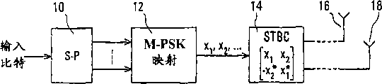
图1说明一种已知的时空分组编码(STBC)发射机的组成部分;Figure 1 illustrates the components of a known space-time block coding (STBC) transmitter;
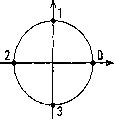
图2说明一种QPSK符号的已知信号点星座;Figure 2 illustrates a known signal point constellation for a QPSK symbol;
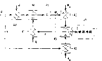
图3说明一种已知的特播编码器;Figure 3 illustrates a known turbo encoder;
图4说明根据本发明的一个实施例、采用两个发射天线的发射机的特播时空格形编码调制(STTCM)编码装置的组成部分;FIG. 4 illustrates the components of a Turbo Space-Time Coding Modulation (STTCM) encoding apparatus employing a transmitter with two transmit antennas according to one embodiment of the present invention;
图5说明卷积或格形编码器的一般形式;Figure 5 illustrates the general form of a convolutional or trellis encoder;
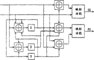
图6说明一种可用于图4的装置中的4-态格形编码器;Figure 6 illustrates a 4-state trellis encoder that may be used in the apparatus of Figure 4;
图7说明一种可用于图4的装置中的8-态格形编码器;Figure 7 illustrates an 8-state trellis encoder that may be used in the apparatus of Figure 4;
图8说明一种可用于图4的装置中的16-态格形编码器;Figure 8 illustrates a 16-state trellis encoder that may be used in the apparatus of Figure 4;
图9说明用于具有四个发射天线的发射机的特播STTCM编码装置中的4-态格形编码器;Figure 9 illustrates a 4-state trellis encoder in a Turbo STTCM encoding arrangement for a transmitter with four transmit antennas;
图10说明用于发射机的一种编码装置的组成部分,其中图9的编码器可根据本发明的另一个实施例来使用;以及Figure 10 illustrates the components of an encoding device for a transmitter, wherein the encoder of Figure 9 can be used according to another embodiment of the invention; and
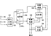
图11说明与图4或图10的装置配合使用的接收机和解码装置的组成部分。FIG. 11 illustrates the components of a receiver and decoding apparatus for use with the apparatus of FIG. 4 or 10. FIG.
详细说明Detailed description
参照附图,图1说明一种已知的时空分组编码(STBC)发射机的组成部分。为了使各个附图中的标号简洁起见,仅给出完全理解先有技术以及本发明的实施例所需的部分。Referring to the drawings, Figure 1 illustrates the components of a known space-time block coding (STBC) transmitter. For the sake of brevity in reference numerals in the various drawings, only those parts necessary for a complete understanding of the prior art as well as the embodiments of the present invention are given.
图1的发射机包括串-并(S-P)转换器10、M-PSK映射功能12以及时空分组编码器(STBC)14,该编码器经由发射机功能、如图1中未标明但以虚线表示的上变频器和功率放大器将输出提供给提供发射分集的至少两个天线16和18。S-P转换器10得到待传递的信息输入比特,并且在到M-PSK映射功能12的两条或更多并行线路上产生输出比特,M-PSK映射功能12从并行比特中产生等能量信号星座的顺序符号x1,x2,...The transmitter of FIG. 1 includes a serial-to-parallel (SP)
例如,如图1所示,映射功能12可将来自S-P转换器10的每种情况下的2个输入比特的格雷码映射提供给图2所示QPSK(正交相移键控)信号点星座的M=4个信号点中相应的信号点,其中信号点分别标识为0至3。为简便起见,在整个说明中假定格雷码QPSK映射,但是可以理解,映射功能12能够对具有任何所需数量M的相位状态的信号点星座提供任何所需映射;例如M=2(为此不需要S-P转换器10)、4或6。For example, as shown in FIG. 1, the
复数所表示的QPSK符号x1,x2,...提供给STBC 14,为简洁起见,在图1中表示为对相应发射天线16和18具有两个输出,但也可对相应较大数量的发射天线具有两个以上的输出。对于所示的两个天线的情况,STBC 14从提供到其输入端的各连续符号对x1和x2形成符号的时空分组,如图1所示。The QPSK symbols x 1 , x 2 , . The transmit antenna has more than two outputs. For the two-antenna case shown, the
更具体地说,STBC功能由T×T正交矩阵Hx表示,其中T是发射天线的数量,从而也是STBC 14的符号输出的数量。对于图1所示T=2的情况,More specifically, the STBC function is represented by a T×T orthogonal matrix H x , where T is the number of transmit antennas and thus the number of symbol outputs of the
根据这个矩阵Hx,对于提供给STBC 14的输入端的各对PSK符号x1和x2,在第一符号间隔中,为天线16提供符号x1以及为第二天线18提供符号x2,在第二符号间隔中,为第一天线16提供符号-x2 *以及为第二天线18提供符号x1 *,其中*表示复共轭。因此各对中的两个PSK符号以不同形式从不同天线在不同时间发送两次,从而提供空间和时间分集。可以看到,矩阵Hx的各列表示在连续间隔中从相应天线发送的符号,各行则表示相应符号发送间隔。According to this matrix H x , for each pair of PSK symbols x 1 and x 2 provided to the input of the
参照图3,已知的特播(并行级联卷积)编码器包括:两个递归系统卷积(RSC)编码器20和22,它们称作特播编码器的成分或分量编码;交织器24;以及选择器26。输入比特提供给一个编码器20的输入端,该编码器在其输出端上产生与输入比特相同的系统比特S1以及奇偶校验比特P1。输入比特也提供给交织器24并由其进行交织,交织比特提供给另一个编码器22的输入端,该编码器在其输出端上产生与交织输入比特相同的系统比特S2和奇偶校验比特P2。两个编码器20和22的输出提供给选择器26的输入端,不过,如图3所示,通常未连接编码器22的系统比特输出端,因为在此输出端上的交织比特绝不会被选择器26所选择。Referring to Figure 3, a known Turbo (parallel concatenated convolutional) encoder comprises: two Recursive Systematic Convolutional (RSC)
选择器26分别从编码器20和22中选择全部系统比特S1以及部分或全部奇偶校验比特P1、P2,并将它们作为输出比特提供给特播编码器的输出端。奇偶校验比特的选择取决于编码器的速率。例如,对于速率1/3(对于每个输入比特有3个输出比特)编码器,选择器26可选择全部奇偶校验比特P1和P2。对于速率1/2(对于每个输入比特有2个输出比特)编码器,选择器26可交替选择奇偶校验比特P1和P2,从而仅输出一半奇偶校验比特P1和一半奇偶校验比特P2,这个过程称作删截。The
在发明背景中引用的特播TCM装置(Robertson等人)中,交织器24对各个m个比特的分组进行操作,它们在各分量编码器(20、22)的输出上映射为例如结合了系统和奇偶校验信息的PSK符号。来自第二分量编码器(22)的符号由符号去交织器进行去交织,输出选择器交替选择从第一分量编码器(20)和去交织器输出的符号。这种情况下的交织器(以及随后的去交织器)必须提供偶对偶以及奇对奇(或偶对奇以及奇对偶)的位置映射。In the Turbo TCM arrangement cited in the Background of the Invention (Robertson et al.), the
发明背景中引用的级联SBTC和特播码(Bauch)装置中,如图3所示的特播编码器的输出比特实际上作为输入比特提供给如图1所示的时空分组编码器,或者来自如Robertson等人所述的特播TCM编码器的输出符号作为输入符号提供给STBC编码器14,如以上参照图1所述。In the concatenated SBTC and Turbo Code (Bauch) arrangement cited in the Background of the Invention, the output bits of the turbo coder shown in Figure 3 are actually provided as input bits to the space-time block coder shown in Figure 1, or The output symbols from the turbo TCM encoder as described by Robertson et al. are provided as input symbols to the
图4说明根据本发明的一个实施例、采用两个发射天线的发射机所用的特播时空格形编码调制(STTCM)编码装置的组成部分。对于图1所示的情况,两个天线标号为16和18,待传递信息的输入比特提供给S-P转换器10,它也通过用于QPSK符号传输的两个输出来说明。图4的其余部分表示特播STTCM编码装置,它包括:两个RSC编码器和映射功能30和32;交织器34;以及选择器36,它具有用于到两个天线16和18的相应传输路径的两个输出。RSC编码器和映射功能30和32的输入上的虚线表示它们以及交织器34可具有用于非QPSK符号的不同数量的输入,如上所述。FIG. 4 illustrates the components of a Turbo Space-Time Coding Modulation (STTCM) encoding apparatus for a transmitter employing two transmit antennas according to one embodiment of the present invention. For the case shown in Figure 1, the two antennas are numbered 16 and 18, and the input bits of the information to be conveyed are supplied to the
从S-P转换器10并行提供的比特由交织器34以分组形式(本例中是以成对形式)进行交织。提供给功能30的非交织比特对和提供给功能32的交织比特对由这些功能进行编码,并映射成QPSK符号,下面将进一步说明。因此,功能30在其两个输出端产生表示对应于输入比特的系统信息的QPSK符号SS1以及表示功能30的递归卷积编码所产生的奇偶校验信息的QPSK符号PS1。同样,功能32在其两个输出上产生表示对应于由交织器34以比特对进行交织的输入比特的系统信息的QPSK符号SS2以及表示功能32的递归卷积编码从交织输入比特对中所产生的奇偶校验信息的QPSK符号PS2。虽然为简便起见在此假定RSC编码和映射功能30、32是相同的,对于以上参照图3所述的特播编码器的分量编码器的情况通常是这样,但这不一定始终这样,这些功能也可彼此不同。The bits supplied in parallel from the
选择器36通过以符号(比特对)率交替为一和零(所述情况为1010...)的控制信号来控制,并执行选择和删截功能,如图4的选择器36中的开关所示。在控制信号的第一状态,例如当控制信号为二进制1时,选择器36的开关状态如图4所示,其中来自RSC编码器和映射功能30的系统符号SS1和奇偶校验符号PS1分别提供给到发射天线16、18的输出通路,未使用功能32的输出SS2和PS2。在控制信号的第二状态,例如当控制信号为二进制0时,选择器36的开关具有其相反的状态,其中来自RSC编码器和映射功能32的系统符号SS2和奇偶校验符号PS2分别提供给到发射天线18、16的输出通路,未使用功能30的输出SS1和PS1。The
可以理解,通过选择器36交替选择非交织系统符号SS1和交织系统符号SS2,以便确保所有系统信息被发送,就需要交织器34将其输入端的偶数位置映射到其输出端的偶数位置以及将其输入端的奇数位置映射到其输出端的奇数位置(或者偶到奇以及奇到偶的位置映射),正如上述Robertson等人的方案的情况一样。设置交织器34以相应地提供这种映射。It can be understood that the non-interleaved system symbol SS1 and the interleaved system symbol SS2 are alternately selected by the
从以上说明以及从图4中可以理解,装置30、32、34和36是以特播编码器的方式来设置的,为此,功能30和32提供特播编码器所需的递归卷积编码,选择器36将特播编码器的选择和删截功能与采用两付天线16、18的发射分集所用的时空分组编码器的功能相结合。由交织器34进行的偶到偶和奇到奇(或偶到奇和奇到偶)位置映射确保表示所有输入比特的系统符号随时间(即在各交织块中)被发送,而不管单独应用于系统符号SS1和SS2的删截。这样,装置30、32、34和36提供了特播编码、递归格形编码调制以及时空编码的组合功能。From the above description and from Fig. 4, it can be understood that the
需要确定所希望的递归格形或卷积编码,从而确定功能30、32的构成,用于以上参照图4所述的装置中。编码过程可通过各种方式来说明,下面所采用的一种方式是通过编码器状态和输出矩阵来进行的。The desired recursive trellis or convolutional coding needs to be determined to determine the composition of the
对于具有N个状态并被提供具有M个可能值(例如在本说明中,对于QPSK的成对输入比特,M=4)的输入符号的编码器,编码器状态矩阵B是N×M矩阵(N行和M列),其元素B(i,j)确定下一个符号的编码器状态,取决于等于从0至N-1的整数的i所表示的当前状态,并且还取决于等于从0至M-1的整数的j所表示的当前输入符号。编码器输出矩阵C也是N×M矩阵,其元素C(i,j)确定在当前编码器状态和当前输入符号同样分别由i和j表示时所产生的输出符号。For an encoder with N states and provided with input symbols having M possible values (e.g. M=4 for pairs of input bits of QPSK in this illustration), the encoder state matrix B is an N×M matrix ( N rows and M columns), whose element B(i, j) determines the encoder state for the next symbol, depending on the current state represented by i equal to an integer from 0 to N-1, and also depending on The current input symbol represented by j of integers up to M-1. The encoder output matrix C is also an NxM matrix whose elements C(i,j) determine the output symbols produced when the current encoder state and the current input symbol are also denoted by i and j, respectively.
对于具有用于供给相应数量天线的T个输出通路的编码器,定义另一个编码器输出矩阵Z,它也是N×M矩阵,由矩阵C导出,具有元素Z(i,j),其中i和j与以上定义相同。各元素Z(i,j)由标识提供给各天线的信号的T个Q相关符号构成,其中Q由调制类型确定,例如对于QPSK,Q=4。这样,各元素由标识提供给天线t的信号的T个Q相关符号Zt(i,j)构成,其中t为从0到T-1的整数。For an encoder with T output paths feeding the corresponding number of antennas, define another encoder output matrix Z, which is also an N×M matrix, derived from matrix C, with elements Z(i,j) where i and j is the same as defined above. Each element Z(i, j) consists of T Q-related symbols identifying the signal provided to each antenna, where Q is determined by the modulation type, eg Q=4 for QPSK. Thus, each element consists of T Q-related symbols Zt (i,j) identifying the signal provided to antenna t, where t is an integer from 0 to T-1.
通过从编码器输出到用于传输的信号点星座的映射功能来进一步说明编码过程。为简便起见,在以下说明中,假定这种映射功能如以上参照图2所述,即用于QPSK符号的格雷码映射。The encoding process is further illustrated by the mapping function from the encoder output to the constellation of signal points used for transmission. For simplicity, in the following description it is assumed that this mapping function is as described above with reference to Figure 2, ie Gray code mapping for QPSK symbols.
虽然对于以上述方式概述的实现能够完整地描述编码过程,但并不足以对代码进行分类。为了后一目的,卷积码可由以下公式来描述:While the encoding process can be fully described for the implementation outlined in the above manner, it is not sufficient to classify the code. For the latter purpose, a convolutional code can be described by the following formula:
编码器状态矩阵公式:Encoder state matrix formula:
以及编码器输出矩阵公式:And the encoder output matrix formula:

其中,Φi是当前编码器状态的n维二进制矢量并且n=log2(N),Ui是m维二进制输入矢量并且m=log2(M),Zi是p维二进制输出矢量,p=log2(P)以及P=QT,表示模2加法(或等效为“异或”功能),G、W、
为了帮助理解这个方面,图5说明卷积或格形编码器的一般构造,它对应于上述最后两个公式。参照图5,这个编码器包括乘法器40至43,它们均被提供相应的增益或加权系数。各输入符号Ui提供给乘法器40和43,当前编码器状态Φi提供给乘法器41和42。乘法器40和41的输出根据上述两个公式中的第一个公式在模2加法器44中组合,该加法器的输出在延迟单元46中被延迟一个符号间隔D以提供下一个编码器状态。乘法器42和43的输出根据上述两个公式中的第二个公式在模2加法器45中组合,该加法器的输出提供给执行如上所述QPSK映射的映射功能47。对于图5中的部分通路,维数m、n和p的矢量的多通路以传统方法由这些通路上的线段来表示。To help understand this aspect, Figure 5 illustrates the general construction of a convolutional or trellis encoder, which corresponds to the last two formulations above. Referring to FIG. 5, this encoder includes
卷积码或格码可采用矩阵W和矩阵

如上所述,以上引用的Tarokh等人的公开中所述的代码是非递归的,因此不适合提供如图4所示的有效特播编码器方案。对于少量的编码器状态,提供最佳代码的增益矩阵的元素可通过计算机搜索和模拟来确定,但这种方法对于具有大量(例如超过8个)编码器状态的编码器则不可行,必须采用其它方法。以下所述的代码通过选择经单一天线传输的原型二进制递归卷积码来确定,利用它来构造采用预期数量的天线的时空编码所用的格子结构,然后修改结果以便对于QPSK来改善它。也可使用包括以其它方式得到的代码在内的其它代码,仅作为示例提供以下代码。As noted above, the code described in the above-cited Tarokh et al. publication is non-recursive and therefore not suitable for providing an efficient turbo encoder scheme as shown in FIG. 4 . For a small number of encoder states, the elements of the gain matrix that provide the optimal code can be determined by computer search and simulations, but this approach is not feasible for encoders with a large number (e.g., more than 8) of encoder states and must be used other methods. The codes described below are determined by choosing a prototype binary recursive convolutional code transmitted over a single antenna, using it to construct the trellis for space-time coding with the expected number of antennas, and then modifying the result to improve it for QPSK. Other codes, including codes obtained in other ways, may also be used, the following codes are provided as examples only.
对于可用于图4的发射机中的4态RSC编码器和QPSK映射功能,矩阵B、C、Z、W、G、以及Hu可如下所示:For a 4-state RSC encoder and QPSK mapping function that can be used in the transmitter of Fig. 4, the matrices B, C, Z, W, G, and H u can be shown as follows:

可用来构成图4的装置中的各功能30和32的这种编码器及其映射功能的实现如图6所示。An implementation of such an encoder and its mapping function that can be used to form the
参照图6,编码器包括:模2加法器50至54;两个延迟元件55和56,每一个均提供一个符号(比特对)间隔D的延迟;以及两个映射功能57和58,每一个功能在其输出端提供在其输入端得到的两个比特到QPSK符号的格雷码映射,如以上参照图2所述。Referring to Figure 6, the encoder comprises: modulo 2
如以上参照图4所述,在功能30的情况下从S-P转换器10提供的或者在功能32的情况下从交织器34提供的一对输入比特在各符号间隔中提供给图6的编码器的输入端。这些比特提供给加法器50的输入端,加法器的输出以及到编码器的比特输入的下面一个(如图所示)提供给映射功能57,它在其输出端产生表示输入比特对的格雷码QPSK映射系统符号。As described above with reference to FIG. 4, a pair of input bits provided from the
到图6的编码器的比特输入的上面一个(如图所示)也提供给各加法器51至54的输入端,到编码器的下面的比特输入也提供给各加法器52和53的另一个输入端。加法器51的输出提供给延迟元件55,该元件的输出提供给各加法器52至54的另一输入端。加法器52的输出提供给延迟元件56,该元件的输出提供给各加法器51、52以及54的另一个输入端。可以看到,图6所示加法器51至54以及延迟元件55、56的设置实现了上述编码器矩阵;例如,从延迟元件55、56到加法器51、52的输入端有三个反馈通路,它们根据上述矩阵W中的三个一进行配置,其中两个延迟元件提供编码器的四个状态。加法器53和54的输出构成对映射功能58的输入,映射功能58根据上式给出的代码在其输出端相应地产生格雷码QPSK映射奇偶校验符号。The upper one (as shown) of the bit inputs to the encoder of FIG. an input terminal. The output of the
对于可用于图4的发射机中的8态RSC编码器和QPSK映射功能,矩阵B、C、Z、W、G、

可用来构成图4的方案中的各功能30和32的这种编码器及其映射功能的实现如图7所示。从以上给出的用于这种8态编码器的公式的比较以及图7所示电路(其中有三个延迟元件以提供8个状态)可以看到,这个电路实现这些公式的递归系统卷积编码。An implementation of such an encoder and its mapping function that can be used to form the
对于可用于图4所示发射机的16态RSC编码器和QPSK映射功能,矩阵B、C、Z、W、G、

可用来构成图4的装置中的各功能30和32的这种编码器及其映射功能的实现如图8所示。从以上给出的用于这种16态编码器的公式的比较以及图8的电路(其中有四个延迟元件以提供16个状态)可以看到,这个电路实现这些公式的递归系统卷积编码。An implementation of such an encoder and its mapping function which may be used to form the
从图4的编码装置以及图6至8的编码器的上述说明可以知道,在每种情况下,对于所述QPSK符号,在一个符号间隔中有两个输入比特,使得四个比特(两个系统信息比特和两个奇偶校验比特)被提供给特播编码装置中的两个编码器中每一个的QPSK映射功能。这八个比特由映射功能映射成四个QPSK符号,以及在两个连续的符号间隔上,一半QPSK符号被选择器36删截,从而在各符号间隔中从两个天线16和18发送两个符号。选择器装置是这样的,在第一符号间隔中,两个天线发送来自得到非交织输入比特的编码器30的系统和奇偶校验信息,以及在第二符号间隔中,两个天线发送来自得到交织输入比特的另一个编码器32的系统和奇偶校验信息,通过在连续的符号间隔中交替从各天线发送系统信息和奇偶校验信息来增强时空分集。From the above description of the encoding device of Fig. 4 and the encoder of Figs. 6 to 8, it can be known that in each case, for the QPSK symbol, there are two input bits in one symbol interval, so that four bits (two system information bits and two parity bits) are supplied to the QPSK mapping function of each of the two encoders in the turbo encoding device. These eight bits are mapped into four QPSK symbols by the mapping function, and on two consecutive symbol intervals, half of the QPSK symbols are punctured by
在上述方案中,映射功能经过设置,使得各QPSK符号完全从系统信息或完全从奇偶校验比特中产生。但是,不一定如此,其它方案也是可能的,例如各QPSK符号从一个系统信息比特和一个奇偶校验比特中产生。换句话说,对于各编码器,可以重新设置到映射功能(例如图6中的56和57)的输入。In the above schemes, the mapping function is set such that each QPSK symbol is generated entirely from system information or entirely from parity bits. However, this is not necessarily the case, other schemes are possible, eg each QPSK symbol is generated from one system information bit and one parity bit. In other words, for each encoder, the inputs to the mapping functions (
以下参照图9作为实例所描述的编码器正是如此,它用于在具有四个发射天线的发射机所用的特播STTCM编码方案中。作为实例,这是QPSK符号的4态格形编码器。在时空分集的两个连续符号间隔中,从四个天线总共发送八个符号,从而通过50%删截,特播编码器装置的两个分量编码器的映射功能提供八个QPSK符号,因此在各符号间隔中,各编码器从其映射功能提供四个QPSK符号。这四个QPSK符号表示四个系统比特和四个奇偶校验比特,所以在这种情况下存在到编码器的四个输入比特线。This is the case for the coder described below as an example with reference to Figure 9, which is used in a Turbo STTCM coding scheme for a transmitter with four transmit antennas. As an example, this is a 4-state trellis encoder for QPSK symbols. In two consecutive symbol intervals with space-time diversity, a total of eight symbols are transmitted from four antennas, so that with 50% puncturing, the mapping function of the two component encoders of the turbo encoder arrangement provides eight QPSK symbols, thus at In each symbol interval, each encoder provides four QPSK symbols from its mapping function. These four QPSK symbols represent four systematic bits and four parity bits, so in this case there are four input bit lines to the encoder.
参照图9,统称为60的四个输入比特线均连接到四个QPSK映射功能61至64的第一输入端,这些映射功能提供到QPSK符号的格雷码映射,如以上参照图2所述。编码器还包括两个延迟元件65和66,每一个元件提供一个符号间隔的延时D,从而确定编码器和模2加法器67至72的四个状态。模2加法器69至72的输出分别连接映射功能61至64的第二输入端。这样,QPSK映射功能61至64均被提供一个系统信息比特和一个奇偶校验比特,并分别产生结合了这种系统和奇偶校验信息的QPSK符号SP-1至SP-4。Referring to FIG. 9 , four input bit lines, collectively referred to as 60 , are each connected to first inputs of four QPSK mapping functions 61 to 64 which provide Gray code mapping to QPSK symbols, as described above with reference to FIG. 2 . The encoder also includes two delay elements 65 and 66 each providing a delay D of one symbol interval to determine the four states of the encoder and modulo-2 adders 67 to 72 . The outputs of the modulo-2 adders 69 to 72 are connected to the second inputs of the mapping functions 61 to 64, respectively. Thus, the QPSK mapping functions 61 to 64 are each provided with a systematic information bit and a parity bit, and generate QPSK symbols SP-1 to SP-4 respectively combining such systematic and parity information.
线60、延迟元件65和66、模-2加法器67至72则以实现下列矩阵W、G、

另外还应当知道,与图9中映射功能61至64的连接是作为实例提供的,对于其它代码及其它情况可重新设置。例如,四个系统比特也可提供给映射功能中的两个,而四个奇偶校验比特可提供给其余两个映射功能。作为另一实例,能够向映射功能之一提供两个系统比特,向另一个映射功能提供两个奇偶校验比特,以及其余两个各被提供一个系统比特和一个奇偶校验比特。但是,对于以下进一步说明,假定图9的特定装置。It should also be understood that the connections to the mapping functions 61 to 64 in Figure 9 are provided as examples and can be reconfigured for other codes and other situations. For example, four systematic bits may also be provided to two of the mapping functions, while four parity bits may be provided to the remaining two mapping functions. As another example, one of the mapping functions could be provided with two systematic bits, the other mapping function with two parity bits, and the remaining two each be provided with one systematic bit and one parity bit. However, for the further description below, the particular arrangement of FIG. 9 is assumed.
图10说明用于具有四个发射天线的发射机的特播STTCM编码装置的组成部分,其中,图9的编码器用来构成特播编码装置的两个分量编码器和映射功能单元80、82。向S-P转换器84提供输入比特,并将其转换为四比特的分组,它们直接作为单元80的输入比特并经交织器86提供给单元82。交织器86对四比特的分组进行交织,保持偶对偶以及奇对奇或者偶对奇以及奇对偶的位置映射,如上所述。统称为SP1的单元80的系统和奇偶校验符号输出连接到选择器88的第一组输入,统称为SP2的单元82的系统和奇偶校验符号输出经可选相位旋转单元90连接到选择器88的第二组输入。选择器88由一和零比特的交替序列控制,从而将其第一和第二组输入在连续符号间隔中交替连接到至标号为92的四个天线的四条输出通路上。Fig. 10 illustrates the components of a turbo STTCM encoding device for a transmitter with four transmit antennas, wherein the encoder of Fig. 9 is used to form the two component encoders and mapping functional units 80, 82 of the turbo encoding device. The input bits are provided to S-P converter 84 and converted into packets of four bits which are provided directly as input bits to unit 80 and to unit 82 via interleaver 86 . The interleaver 86 interleaves the four-bit packets, maintaining even-even and odd-odd or even-odd and odd-even positional mappings, as described above. The systematic and parity symbol outputs of unit 80, collectively referred to as SP1, are connected to a first set of inputs of a selector 88, and the systematic and parity symbol outputs of unit 82, collectively referred to as SP2, are connected to the selector via an optional phase rotation unit 90 88's second set of inputs. Selector 88 is controlled by an alternating sequence of one and zero bits to alternately connect its first and second set of inputs to the four output paths to the four antennas generally designated 92 in successive symbol intervals.
可选相位旋转单元90提供各符号的π/2的相位旋转,并且可包含四个乘法器,每一个乘法器经过设置,用来将为其提供的QPSK符号中相应的一个与信号ejπ/2相乘,已经证明,这能够改善某些情况下的性能,尤其是在采用四个天线的发射机中。这种相位旋转单元可省略,若需要,可在上述仅采用两个天线的发射机所用的编码装置中提供类似的相位旋转单元,和/或可以为部分但不是全部QPSK符号提供相位旋转。An optional phase rotation unit 90 provides a phase rotation of π/2 for each symbol and may comprise four multipliers, each multiplier arranged to compare a corresponding one of the QPSK symbols supplied thereto with the signal e jπ/ 2 , which has been shown to improve performance in some cases, especially in transmitters employing four antennas. Such a phase rotation unit may be omitted, and if desired, a similar phase rotation unit may be provided in the above-mentioned encoding arrangement for a transmitter employing only two antennas, and/or phase rotation may be provided for some but not all QPSK symbols.
因此,可以看到,选择器88在每两个连续符号间隔的第一个间隔中将来自得到非交织输入比特的单元80的系统和奇偶校验信息QPSK符号连接到其输出,并在每两个连续符号间隔的第二个间隔中将来自得到交织输入比特的单元82的系统和奇偶校验信息QPSK符号连接到其输出。Thus, it can be seen that the selector 88 couples the systematic and parity information QPSK symbols from the unit 80 from which the non-interleaved input bits are derived to its output in the first of every two consecutive symbol intervals, and The systematic and parity information QPSK symbols from the unit 82 that derives the interleaved input bits are concatenated to its output in a second interval of N consecutive symbol intervals.
图11说明与图4或图10的装置配合使用的接收机和解码装置的组成部分。如图11所示,接收机包括两个天线100和101,来自天线的信号被连接到最大比结合器(MRC)102并在其中结合,从而在线103上在其输出端产生用于解码的信号。为简单起见,接收机的其它已知部分、如下变频器和信号放大器及抽样器等未在图11中标明,但由从天线100和101至MRC 102的通路中的虚线来表示。虽然图11所示的接收机具有两个天线,但也可只具有一个天线或两个以上天线,还可使用除最大比结合之外的其它方法在线103上产生用于解码的信号。FIG. 11 illustrates the components of a receiver and decoding apparatus for use with the apparatus of FIG. 4 or 10. FIG. As shown in Figure 11, the receiver comprises two
解码装置包括:去删截选择器104;两个软格码解码器105和106;交织器107,以与发射机中的特播编码装置的交织器、如图4所示装置中的交织器34相同的方式工作;以及去交织器108,以与交织器107相反的方式工作。单元105至108以特播码解码器领域中普遍知道的方式进行设置,其中第一解码器105产生由交织器107进行交织并作为软输入提供给第二解码器106的软输出(概率矢量),它还产生由去交织器108进行去交织并作为软输入提供给迭代装置中的第一解码器的软输出,第一解码器105对非交织输入矢量进行操作,以及第二解码器106对交织输入矢量进行操作,输入矢量从要在线103上进行解码的信号中导出。在预期的迭代次数之后,从解码装置中、例如从图11所示的去交织器108的输出中导出输出。The decoding device comprises:
从前面的说明可以知道,图4或图10的编码装置在连续的符号间隔中交替提供从非交织比特中导出的符号以及从交织输入比特中导出的符号。选择器104相应地由交替为一和零的控制信号来控制,如图11所示,以便在连续的符号间隔中交替具有两种状态中的每一种。在这两种状态中的第一状态中,选择器由具有图11所示状态的开关来表示,并对应于从非交织输入比特导出的符号的传输,选择器104将线103上的信号作为输入矢量提供给第一解码器105,并将零输入矢量提供给第二解码器106。相反,在这两种状态中的第二状态中,选择器由具有与图11所示相反的状态的开关来表示,并对应于从交织输入比特导出的符号的传输,选择器104将零输入矢量提供给第一解码器105,并将线103上的信号作为输入矢量提供给第二解码器106。这样,第一解码器105对非交织数据进行操作,第二解码器106则根据需要对交织数据进行操作。解码器的复杂度通过在交替符号间隔中向这些解码器提供零输入矢量而得到简化。It can be known from the foregoing description that the encoding apparatus in FIG. 4 or FIG. 10 alternately provides symbols derived from non-interleaved bits and symbols derived from interleaved input bits in consecutive symbol intervals. The
以上根据本发明的实施例所述的编码和解码装置的性能可有效地与本发明背景中所引用的先有技术(Bauch)中已知的级联特播TCM和STBC装置的性能进行比较。在具有两个发射天线、两个接收天线、1000比特(500符号)的交织器分组长度以及256Hz的多普勒频率的每种情况下,按照1至4dB的信号(每信息比特的能量)噪声比的范围上大约0.75至1.1dB的误码率,已经证明上述根据本发明的装置与Bauch级联方案相比提供了显著改善。The performance of the encoding and decoding arrangement described above according to the embodiments of the present invention can be effectively compared with the performance of cascaded turbo TCM and STBC arrangements known in the prior art (Bauch) cited in the background of the present invention. In each case with two transmit antennas, two receive antennas, an interleaver block length of 1000 bits (500 symbols), and a Doppler frequency of 256 Hz, in terms of signal (energy per information bit) noise of 1 to 4 dB With a bit error rate in the range of about 0.75 to 1.1 dB, it has been demonstrated that the arrangement according to the invention described above provides a significant improvement over the Bauch cascade scheme.
虽然以上对本发明的特定实施例进行了详细说明,但是可以理解,大量修改、变更以及改变均可在权利要求所定义的本发明范围之内进行。While specific embodiments of the invention have been described in detail, it will be appreciated that numerous modifications, changes and changes are possible within the scope of the invention as defined by the appended claims.
Claims (31)
Applications Claiming Priority (1)
| Application Number | Priority Date | Filing Date | Title |
|---|---|---|---|
| PCT/RU2000/000475 WO2002043314A1 (en) | 2000-11-22 | 2000-11-22 | Methods and apparatus for turbo space-time trellis coding |
Publications (2)
| Publication Number | Publication Date |
|---|---|
| CN1479983A CN1479983A (en) | 2004-03-03 |
| CN100407612C true CN100407612C (en) | 2008-07-30 |
Family
ID=20129572
Family Applications (1)
| Application Number | Title | Priority Date | Filing Date |
|---|---|---|---|
| CN008201234A Expired - Lifetime CN100407612C (en) | 2000-11-22 | 2000-11-22 | Method and device for turbo space-time grid coding |
Country Status (9)
| Country | Link |
|---|---|
| US (1) | US7843888B1 (en) |
| EP (1) | EP1340331B1 (en) |
| JP (1) | JP4618977B2 (en) |
| CN (1) | CN100407612C (en) |
| AT (1) | ATE352915T1 (en) |
| AU (1) | AU2001236258A1 (en) |
| CA (1) | CA2429687C (en) |
| DE (1) | DE60033198T2 (en) |
| WO (1) | WO2002043314A1 (en) |
Families Citing this family (28)
| Publication number | Priority date | Publication date | Assignee | Title |
|---|---|---|---|---|
| JP4331563B2 (en) * | 2002-10-10 | 2009-09-16 | 三星電子株式会社 | Transceiver for supporting transmit antenna diversity using space-time block code |
| ATE452478T1 (en) * | 2002-10-18 | 2010-01-15 | Panasonic Corp | CONSTELLATION REARRANGEMENT FOR TRANSMISSION DIVERSITY TYPES |
| KR100547784B1 (en) | 2003-01-21 | 2006-01-31 | 삼성전자주식회사 | Apparatus and method for transmitting and receiving data in mobile communication system using space-time trellis code |
| KR100526511B1 (en) | 2003-01-23 | 2005-11-08 | 삼성전자주식회사 | Apparatus for transmitting/receiving pilot sequence in mobile communication system using space-time trellis code and method thereof |
| GB2399719A (en) * | 2003-03-18 | 2004-09-22 | Nokia Corp | Transmission of data with forward error correction information |
| US7450661B2 (en) | 2003-05-02 | 2008-11-11 | Samsung Electronics Co., Ltd. | Space-time coding method and apparatus in a mobile communication system |
| US8064528B2 (en) | 2003-05-21 | 2011-11-22 | Regents Of The University Of Minnesota | Estimating frequency-offsets and multi-antenna channels in MIMO OFDM systems |
| US7209714B2 (en) * | 2003-08-29 | 2007-04-24 | Nokia Corporation | Apparatus, and associated method, for communicating data at selected levels of diversity in a radio communication system |
| GB2407007B (en) * | 2003-10-09 | 2006-06-28 | Toshiba Res Europ Ltd | Estimator for mimo receiver |
| KR101050570B1 (en) * | 2003-12-03 | 2011-07-19 | 삼성전자주식회사 | Apparatus and method for data transmission and reception for performance improvement in mobile communication system using space-time trellis code |
| CN100394695C (en) * | 2003-12-18 | 2008-06-11 | 中国科学院半导体研究所 | A Constructing Method of Complementary Convolutional Codes Suitable for Frequency Diversity Transmission |
| CN1951050B (en) | 2004-03-15 | 2013-10-30 | 苹果公司 | Pilot design for OFDM systems with four transmit antennas |
| CN103297204B (en) * | 2004-04-02 | 2017-03-01 | 苹果公司 | Space Time Transmit Diversity system and method for OFDM application |
| EP3528575B1 (en) | 2004-06-22 | 2020-12-16 | Apple Inc. | Enabling feedback in wireless communication networks |
| EP3537681B1 (en) | 2004-06-24 | 2020-10-07 | Apple Inc. | Preambles in ofdma system |
| WO2006002550A1 (en) | 2004-07-07 | 2006-01-12 | Nortel Networks Limited | System and method for mapping symbols for mimo transmission |
| CN1599260B (en) * | 2004-07-23 | 2010-05-05 | 西安电子科技大学 | Space hour coding method based on odd-even checking code |
| CA2601151A1 (en) * | 2005-03-14 | 2006-09-21 | Telcordia Technologies, Inc. | Iterative stbicm mimo receiver using group-wise demapping |
| US8320499B2 (en) * | 2005-03-18 | 2012-11-27 | Qualcomm Incorporated | Dynamic space-time coding for a communication system |
| JP2008547303A (en) * | 2005-06-24 | 2008-12-25 | コーニンクレッカ フィリップス エレクトロニクス エヌ ヴィ | Method and apparatus for space-time turbo channel encoding / decoding in a wireless network |
| JP4675312B2 (en) | 2006-11-30 | 2011-04-20 | 富士通株式会社 | Encoding device, decoding device, transmitter, and receiver |
| KR101498052B1 (en) * | 2007-09-19 | 2015-03-03 | 엘지전자 주식회사 | Method for multiplexing data information and control information in a wireless mobile communication system |
| KR101467791B1 (en) | 2007-11-05 | 2014-12-03 | 엘지전자 주식회사 | Method for multiplexing data and control information |
| US8281211B2 (en) * | 2008-05-15 | 2012-10-02 | Nokia Corporation | System and method for relay coding |
| JP2008263631A (en) * | 2008-05-26 | 2008-10-30 | Toshiba Corp | Radio communication system |
| WO2010012123A1 (en) * | 2008-07-30 | 2010-02-04 | 上海贝尔股份有限公司 | A method for uplink/downlink logic topology structure management in a mesh network and the apparatus thereof |
| US9184958B2 (en) * | 2011-11-07 | 2015-11-10 | Blackberry Limited | System and method of encoding and transmitting codewords |
| WO2013070189A1 (en) * | 2011-11-07 | 2013-05-16 | Research In Motion Limited | System and method of encoding and transmitting codewords |
Citations (3)
| Publication number | Priority date | Publication date | Assignee | Title |
|---|---|---|---|---|
| CN1194506A (en) * | 1997-03-04 | 1998-09-30 | 美国电报电话公司 | Multi-tone DPSK modem based on FFT |
| US5907592A (en) * | 1995-10-31 | 1999-05-25 | Levinson; Reuven | Axially incremented projection data for spiral CT |
| US5907582A (en) * | 1997-08-11 | 1999-05-25 | Orbital Sciences Corporation | System for turbo-coded satellite digital audio broadcasting |
Family Cites Families (7)
| Publication number | Priority date | Publication date | Assignee | Title |
|---|---|---|---|---|
| JP2000031837A (en) * | 1998-07-10 | 2000-01-28 | Kokusai Electric Co Ltd | Encoding method |
| US6298463B1 (en) * | 1998-07-31 | 2001-10-02 | Nortel Networks Limited | Parallel concatenated convolutional coding |
| US6356605B1 (en) * | 1998-10-07 | 2002-03-12 | Texas Instruments Incorporated | Frame synchronization in space time block coded transmit antenna diversity for WCDMA |
| US7436895B1 (en) * | 2000-03-01 | 2008-10-14 | Spyder Navigations L.L.C. | Concatenated space-time coding |
| JP4543479B2 (en) * | 2000-03-02 | 2010-09-15 | ソニー株式会社 | Communication system and method |
| JP2001257602A (en) * | 2000-03-10 | 2001-09-21 | Seiko Epson Corp | Data error correction method and apparatus |
| US7020072B1 (en) * | 2000-05-09 | 2006-03-28 | Lucent Technologies, Inc. | Orthogonal frequency division multiplexing transmit diversity system for frequency-selective fading channels |
-
2000
- 2000-11-22 AT AT00991834T patent/ATE352915T1/en not_active IP Right Cessation
- 2000-11-22 DE DE60033198T patent/DE60033198T2/en not_active Expired - Lifetime
- 2000-11-22 WO PCT/RU2000/000475 patent/WO2002043314A1/en active IP Right Grant
- 2000-11-22 US US10/432,216 patent/US7843888B1/en not_active Expired - Lifetime
- 2000-11-22 EP EP00991834A patent/EP1340331B1/en not_active Expired - Lifetime
- 2000-11-22 JP JP2002544916A patent/JP4618977B2/en not_active Expired - Lifetime
- 2000-11-22 CN CN008201234A patent/CN100407612C/en not_active Expired - Lifetime
- 2000-11-22 AU AU2001236258A patent/AU2001236258A1/en not_active Abandoned
- 2000-11-22 CA CA2429687A patent/CA2429687C/en not_active Expired - Lifetime
Patent Citations (3)
| Publication number | Priority date | Publication date | Assignee | Title |
|---|---|---|---|---|
| US5907592A (en) * | 1995-10-31 | 1999-05-25 | Levinson; Reuven | Axially incremented projection data for spiral CT |
| CN1194506A (en) * | 1997-03-04 | 1998-09-30 | 美国电报电话公司 | Multi-tone DPSK modem based on FFT |
| US5907582A (en) * | 1997-08-11 | 1999-05-25 | Orbital Sciences Corporation | System for turbo-coded satellite digital audio broadcasting |
Also Published As
| Publication number | Publication date |
|---|---|
| DE60033198T2 (en) | 2007-05-03 |
| JP2004523938A (en) | 2004-08-05 |
| JP4618977B2 (en) | 2011-01-26 |
| EP1340331B1 (en) | 2007-01-24 |
| ATE352915T1 (en) | 2007-02-15 |
| CN1479983A (en) | 2004-03-03 |
| CA2429687A1 (en) | 2002-05-30 |
| EP1340331A1 (en) | 2003-09-03 |
| CA2429687C (en) | 2012-01-10 |
| WO2002043314A1 (en) | 2002-05-30 |
| DE60033198D1 (en) | 2007-03-15 |
| US7843888B1 (en) | 2010-11-30 |
| AU2001236258A1 (en) | 2002-06-03 |
Similar Documents
| Publication | Publication Date | Title |
|---|---|---|
| CN100407612C (en) | Method and device for turbo space-time grid coding | |
| JP2004523938A5 (en) | ||
| Chen et al. | An improved space-time trellis coded modulation scheme on slow Rayleigh fading channels | |
| Grimm et al. | Further results on space-time coding for Rayleigh fading | |
| US7436895B1 (en) | Concatenated space-time coding | |
| US6678263B1 (en) | Method and constructions for space-time codes for PSK constellations for spatial diversity in multiple-element antenna systems | |
| US7409013B2 (en) | Super-orthogonal space-time trellis codes, and applications thereof | |
| Cui et al. | Performance of parallel concatenated space-time codes | |
| Firmanto et al. | Space-time turbo trellis coded modulation for wireless data communications | |
| Hong et al. | Space-time turbo trellis codes for two, three, and four transmit antennas | |
| KR101050570B1 (en) | Apparatus and method for data transmission and reception for performance improvement in mobile communication system using space-time trellis code | |
| EP1340335A2 (en) | Space-time turbo trellis coding arrangement and method thereof | |
| Yan et al. | Robust space-time block coding for rapid fading channels | |
| Firmanto et al. | Design of space-time turbo trellis coded modulation for fading channels | |
| US20060274848A1 (en) | Method and system of convolutive coding for the transmission of space-time block codes according to the technique termed golden code | |
| US20030072386A1 (en) | Apparatus, and associated method, for Forming a Systematic, Recursive, Space-time Code | |
| MYLSAMY et al. | Space-time trellis code’s performance evaluation considering both feed forward and recursive structure across wireless channels | |
| Shin | Iterative decoding for layered space-time codes | |
| Yu et al. | Full-rate complex orthogonal space-time block code for multiple antennas | |
| Yuan et al. | Design of space-time turbo TCM on fading channels | |
| Li et al. | Optimization of space-time block codes based on multidimensional super-set partitioning | |
| Xie et al. | Combined turbo-TCM and differential unitary space-time modulation | |
| KR100403086B1 (en) | Space-time trellis code construction method for wireless communications | |
| Oh et al. | Space-time codes with full antenna diversity using weighted nonbinary repeat-accumulate codes | |
| Motwani | Full rate space-time turbo codes for general constellations |
Legal Events
| Date | Code | Title | Description |
|---|---|---|---|
| C06 | Publication | ||
| PB01 | Publication | ||
| C10 | Entry into substantive examination | ||
| SE01 | Entry into force of request for substantive examination | ||
| C14 | Grant of patent or utility model | ||
| GR01 | Patent grant | ||
| ASS | Succession or assignment of patent right |
Owner name: APPLE COMPUTER, INC. Free format text: FORMER OWNER: YANXING BIDEKE CO., LTD. Effective date: 20130708 Owner name: YANXING BIDEKE CO., LTD. Free format text: FORMER OWNER: NORTEL NETWORKS LTD (CA) Effective date: 20130708 |
|
| C41 | Transfer of patent application or patent right or utility model | ||
| TR01 | Transfer of patent right |
Effective date of registration: 20130708 Address after: American California Patentee after: APPLE Inc. Address before: American New York Patentee before: NORTEL NETWORKS LTD. Effective date of registration: 20130708 Address after: American New York Patentee after: NORTEL NETWORKS LTD. Address before: Quebec Patentee before: NORTEL NETWORKS Ltd. |
|
| EE01 | Entry into force of recordation of patent licensing contract |
Application publication date: 20040303 Assignee: HUAWEI TECHNOLOGIES Co.,Ltd. Assignor: APPLE Inc. Contract record no.: 2015990000754 Denomination of invention: Method and device for turbo space-time trellis coding Granted publication date: 20080730 License type: Common License Record date: 20150827 |
|
| LICC | Enforcement, change and cancellation of record of contracts on the licence for exploitation of a patent or utility model | ||
| CX01 | Expiry of patent term |
Granted publication date: 20080730 |
|
| CX01 | Expiry of patent term |