CN100406911C - Radiation detector arrangement comprising multiple line detector units - Google Patents
Radiation detector arrangement comprising multiple line detector units Download PDFInfo
- Publication number
- CN100406911C CN100406911C CN038038404A CN03803840A CN100406911C CN 100406911 C CN100406911 C CN 100406911C CN 038038404 A CN038038404 A CN 038038404A CN 03803840 A CN03803840 A CN 03803840A CN 100406911 C CN100406911 C CN 100406911C
- Authority
- CN
- China
- Prior art keywords
- detector cells
- dimension detector
- dimension
- cells
- detector
- Prior art date
- Legal status (The legal status is an assumption and is not a legal conclusion. Google has not performed a legal analysis and makes no representation as to the accuracy of the status listed.)
- Expired - Fee Related
Links
Images


Classifications
-
- G—PHYSICS
- G01—MEASURING; TESTING
- G01T—MEASUREMENT OF NUCLEAR OR X-RADIATION
- G01T1/00—Measuring X-radiation, gamma radiation, corpuscular radiation, or cosmic radiation
- G01T1/16—Measuring radiation intensity
-
- G—PHYSICS
- G01—MEASURING; TESTING
- G01T—MEASUREMENT OF NUCLEAR OR X-RADIATION
- G01T1/00—Measuring X-radiation, gamma radiation, corpuscular radiation, or cosmic radiation
- G01T1/29—Measurement performed on radiation beams, e.g. position or section of the beam; Measurement of spatial distribution of radiation
- G01T1/2914—Measurement of spatial distribution of radiation
- G01T1/2921—Static instruments for imaging the distribution of radioactivity in one or two dimensions; Radio-isotope cameras
- G01T1/2935—Static instruments for imaging the distribution of radioactivity in one or two dimensions; Radio-isotope cameras using ionisation detectors
Landscapes
- Physics & Mathematics (AREA)
- Health & Medical Sciences (AREA)
- Life Sciences & Earth Sciences (AREA)
- General Physics & Mathematics (AREA)
- High Energy & Nuclear Physics (AREA)
- Molecular Biology (AREA)
- Spectroscopy & Molecular Physics (AREA)
- Apparatus For Radiation Diagnosis (AREA)
- Measurement Of Radiation (AREA)
- Analysing Materials By The Use Of Radiation (AREA)
Abstract
A radiation detector arrangement for imaging of an object comprises multiple line detector units (41), each being arranged for one-dimensional imaging of the respective ray bundle. The detector units are arranged parallel in a two-dimensional array. The detector units are sited in rows (44; 61) and stacks (45; 63), the rows being parallel with the detector unit and the stacks being orthogonal thereto, where the one-dimensional detector units in each row are together capable of detecting the object in one dimension. A device (87-89, 91) is provided for moving the detector units relative the object parallel with the stacks at least a distance corresponding to the distance (s1) between two adjacent detector units in the stacks.
Description
Technical field
The present invention relates to be used for object is carried out the ionizing radiation detector device based on scanning of two-dimensional detection.
Background technology
Generally speaking since the gas ionization radiation detector cheap, can utilize gas multiplication and remarkable amplifying signal amplitude and be suitable for carrying out the detection of high spatial resolution, so the gas ionization radiation detector is very attractive.
A kind of gas ionization radiation detector of particular type is such: its electronics that discharges by the interaction between photon and the gas atom can be removed along the direction perpendicular to the incident radiation line substantially.Therefore, but the obvious improvement of implementation space resolution.
This detector comprises planar cathode and anode assembly usually respectively, and is arranged in the ionizable gas in the space that is formed between described negative electrode and the anode assembly.Arrange described detector, feasible planar radiation line from radiation source can and be arranged essentially parallel to the negative electrode and the anode assembly side direction that are used for the described ionizable gas of ionization between negative electrode that is used for the described ionizable gas of ionization and anode assembly and enter described detector.In addition, between described electrode, apply a voltage, be used for drifting about and doubling selectively at the electronics that ionization process produced of ionizable gas.The layout readout device is connected with described anode and is used to survey the electric charge that is generated by drift electron.
Described detector obviously can provide instantaneous one dimension image, but for realizing two-dimensional imaging, described detector and selectable radiation source have to move along the direction that is horizontally through the one dimension detector array with respect to described object to be checked, write down a plurality of read numbers simultaneously.Yet this two-dimensional detection based on scanning expends time in, and when imaging impracticable during than large tracts of land.In addition, if object to be checked is the human or animal, the risk that exists the human or animal in scanning process, to move so, this will make image valueless or at least seriously reduced the quality of the image that is obtained.
In order to reduce sweep time, Francke etc. are at United States Patent (USP) 6,118, have proposed a kind of stacked detectors device in 125, use this device can realize scanning to multirow.Described device comprises x-ray source, and described x-ray source has produced one group of fan-shaped plan X-ray beam that is used to shine the object for the treatment of imaging with a plurality of collimator windows.Transmission enters described stacked detectors by a plurality of second collimator windows selectively by the described beam of described object, and described second collimator windows is aimed at X-ray beam.Described device moves so that scan an object to be detected as a unit.
Summary of the invention
In some purposes for example in the medical applications, the area size for the treatment of imaging can be 50 centimetres of 50 cm x, and the inventor noticed as United States Patent (USP) 6,118, described in 125 be used for than the stacked detectors device of large-area applications make and use aspect impracticable.Being difficult to keep foozle and producing the high spatial resolution detector cells in a large number needs higher efficient, consistance and quality.
So it is a kind of to carry out the ionizing radiation detector device based on scanning with high spatial resolution of two-dimensional detection than the general objective thing that fundamental purpose of the present invention is to provide.
At this on the one hand, objectives are to provide a kind of like this detector assembly, and described detector assembly is suitable for a large amount of productions, and can produce high quality graphic, for example is used for medical inspection.
Another object of the present invention is to provide a kind of like this detector assembly, and described detector assembly comprises a plurality of row detectors unit in closeer matrix, to shorten sweep time and scanning distance.
Another object of the present invention is to provide a kind of like this detector assembly, described reliable, accurately, cheap and have long serviceable life.
Another object of the present invention is to provide a kind of like this detector assembly, scan more than the same area of a row detector unit by using object, also can be known as the repeated sampling technology, described detector assembly can reduce the problem that is produced by out of use inefficacy passage (being the single sensing element of described readout device).
Another object of the present invention is to provide a kind of like this detector assembly, wherein by using the brief moment picture of single each part of row detector unit record object, can will reduce to minimum by moving cause fuzzy, wherein, in possible the moving of limited a period of time internal object thing, the heartbeat of patient in for example checking only can influence the capable image of limited quantity, and can not influence the whole two dimensional images that have two-dimensional detector of the prior art to obtain.
Another object of the present invention is to provide a kind of like this detector assembly, wherein by the repeated sampling technology, promptly write down a plurality of images in each position, make each part of two dimensional image of described object form by a plurality of capable image common combination at different time record, thereby can further alleviate by the various blurring effects that cause that move, wherein said object most probable in all various capable record images processes does not move.
Another object of the present invention is to provide a kind of like this detector assembly, wherein in matrix, arrange a plurality of row detectors unit, to be provided at the lap between the passage (being the sensing element of described row detector) that is positioned at distal edge, to alleviate possible edge effect, for example lower in the distal edge sensitivity of described row detector.
These and other objects are by obtaining as detector assembly claimed in the dependent claims.
The inventor has found to be suitable for mass-produced, the less ionizing radiation detector unit of high precision by arranging in the two-dimensional array mode, and be provided for than the general objective thing for example the breast high-precision two-dimensional imaging in BE based on scanning detector assembly.Described detector assembly is arranged embarks on journey in groups, and wherein the detector cells in each row is staggered, and has lap between the adjacent detector unit along the direction of described row.In addition, described two-dimensional array is disposed in substantially in the radiation direction plane orthogonal with the incident ionization radial line.
By detailed description and accompanying drawing 1-7 to the preferred embodiments of the present invention given below, further feature of the present invention and advantage will be clearer and more definite.Described accompanying drawing only is illustrative, rather than limitation of the present invention.
Description of drawings
Fig. 1 schematically shows and is used in the cross-sectional side elevation view based on the detector cells in the detector assembly of scanning of the present invention;
Fig. 2 schematically shows the front elevation of detector cells among Fig. 1, wherein removes a part of incident collimating apparatus;
Fig. 3 schematically shows the cut-open view of the detector cells A-A along the line among Fig. 1;
Fig. 4 schematically shows the front elevation based on the detector assembly that scans according to first embodiment of the invention, comprises the detector cells among a plurality of Fig. 1-3 in this device;
Fig. 5 is the floor map of upstream collimator, described upstream collimator can be comprised among Fig. 4 for example based among the detector assembly embodiment of scanning to reduce the suffered radiation dose of object in inspection;
Fig. 6 schematically shows the front elevation based on the detector assembly that scans according to second embodiment of the invention, comprises the detector cells among a plurality of Fig. 1-3 in this device; With
Fig. 7 schematically shows the side view that is used for the device of BE according to of the present invention, this device comprise among Fig. 4 or Fig. 6 shown in arbitrary figure based on the detector assembly of scanning and upstream collimator shown in Figure 5.
Embodiment
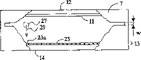
With reference to figure 1-3, be respectively to be used in the cross-sectional side elevation view based on the detector cells in the detector assembly of scanning of the present invention, to remove front elevation and transverse section vertical view after the collimating apparatus part, this detector cells is briefly described.
With this detector cells orientation, make plane X beam 1 can laterally enter between cathode assembly 3 and the anode assembly 5.Slit shape collimating apparatus 7 and radiation transparent window 9 are set, to form the inlet that X-ray beam 1 enters this detector cells in the front portion of this detector cells.This slit shape collimating apparatus 7 can be for example thin metal foil of tungsten, and described metal forming is bonded to the entrance side of this detector cells, etches a slit in described metal forming; This radiation transparent window 9 can be thin plastics or carbon fiber sheet.
In the electrode assembly 3,5 each comprises the conductive electrode layer 11,13 that is subjected to 12,14 supportings of base dielectric layer separately respectively, wherein with described device orientation, makes cathode layer 11 relative with anode layer 13.Described electrode assembly 3 and 5 is the plane preferably, and rectangle also is parallel to each other.Described anode and cathode assembly 3,5 can be the glass plate that is coated with metal.The another kind of selection is that described cathode layer 11 can contain doped silicon and be adhered on the base dielectric layer of being made by glass.
Described electrode assembly 3 and 5 and window 9 preferably and sidewall 15,16,17 limit a sealed chamber 19 that can be full of a kind of gas or gaseous mixture together.The another kind of selection is that described electrode assembly 3 and 5 is disposed in the outside airtight sleeve pipe (not shown).Ionizable gas or gaseous mixture for example can comprise krypton and carbon dioxide or xenon and carbon dioxide.Described gas can be under the pressure, and pressure limit is 1-20atm preferably.
High voltage direct current (DC) supply unit (not shown in Fig. 1-3) is set, its objective is keep negative electrode 11 and anode 13 be in suitable potential be used for wherein electronics and the drift of ion and the electrode that amplifies selectively between the inner electric field that produces.Be that in use negative electrode 11 keeps negative voltage-V easily
1, and anode 13 ground connection.
In addition, this detector cells comprises and is used to survey towards the electronics of anode 13 drifts and/or towards the readout device of the ion of negative electrode 11 drifts.Described readout device self is made of anode assembly 5 as Figure 1-3.The another kind of selection is can arrange an independent readout device near the anode 13 or near the negative electrode 11 or on other ground.
For the one-dimensional image performance is provided, described anode/readout layer 13 comprises row's conduction or a semiconduction element or a bar 23, and described element or bar are arranged side by side and mutual electrical isolation on base dielectric layer 14.Parallax in the image that is detected for compensation, and the spatial resolution of enhancing is provided thus, described anode/read bar extend along the direction that is parallel at the X-ray beam incident photon of position basically.Thereby if point source provides divergent beam, described anode/read bar 23 is arranged to similar fan-shaped configuration.
In the configuration (not shown) of the optional anode/readout device of another kind, described quilt is further divided into the section along the incident X-rays direction, the mutual electrical isolation of described each section and being connected with the electronic equipment of processing usefulness separately.This readout device can be used to energy-resolved detection of radiation.In this respect, specifically quote our the Swedish patent application No.0001167-6 in the power spectrum resolved detection that is entitled as ionising radiation of examining of proposition on March 31st, 2000, described application is referred to herein and is included.
Each anode/read bar preferably is connected with reading with signal processing apparatus (not shown in Fig. 1-3), can handle respectively from the signal of each bar in the above.Because described also constitutes anode, therefore need the suitable web member separately that is used for.
At the one dimension readout device is under the situation of autonomous device, and described anode layer 13 obviously can form is not with described unitary electrode.
Be to be appreciated that for convenience of explanation the distance between the electrode layer 11 and 13 in Fig. 1 and 2 is by obviously exaggerative.As example geometry, described detector cells can be 40 mm wides, 2 millimeters thick and 35 millimeters deep, and described interelectrode distance can be between 0.05 millimeter-2 millimeters.The width W that is used to regulate the collimator slit of the radiation fin thickness that enters detector cells can be as small as 10 microns or wide to 2 millimeters or bigger.
Each is read bar 23 and can be 10 microns-2 mm wides, this means can be arranged side by side hundreds of or thousands of bars in the single detector unit, promptly far more than the quantity shown in the figure.
In the operation, the X-ray is by being parallel to and entering detector cells near the collimator slit of cathode assembly 3.The X-ray changes the exponential probability distribution of gas volume in early days according to most of X-rays, interacts with gas in this detector cells.Average interaction length is generally the 10-100 millimeter.
When take place interacting, X-ray photons 25 transmits its energy to passes through known processes such as photoelectric effect, Compton scattering and/or Auger effect and the electronics that is released in the gas atom from atom.Described electronics passes this gas and bumps with new gas atom, discharges more electronics thus, has finally lost its whole energy and stops until described electronics.In this course, produce the cloud 27 that constitutes by thousands of electronics usually.
By applying electric field U between negative electrode 11 and anode 13, these electronics are attracted (in Fig. 1-2 vertically to) towards anode along direction 29, and described direction is perpendicular with the track of incident X-ray photons substantially.If the electric field that applied is enough strong, described electronics obtains enough energy with knocking-on other electronics from described gas, and described other electronics is accelerated again and with knocking-on other the more electronics of the mode of snowslide.This process is referred to as the gas snowslide and amplifies.Because now a large amount of electronics are near anode, they induce electric signal in the bar 23a of the most close cloud 27.
The electronic installation of reading that described electric signal is connected on described detects.In these electronic installations, described signal is exaggerated and compares with critical voltage.If described signal surpasses critical voltage, the counter of these special uses be activated and the numerical value of former storage on add 1.By this way, the bombardment quantity of X-ray on each anode strap is counted.This method is called as photon counting method.
The another kind of selection be, can be integrated in the individual digit relevant with the gross energy that is accumulated jointly by all X-rays from the signal of many X-rays.
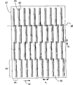
With reference now to Fig. 4,, schematically show front elevation among the figure based on the detector assembly that scans according to first embodiment of the invention, comprise the detector cells among a plurality of Fig. 1-3 in this detector assembly.
Described detector assembly comprises that a plurality of modes with two-dimensional arrangements are arranged in the row detector unit 41 on the total supporting structure 42, and described row detector unit entrance slit 43 separately is towards the front portion of described layout.The Fig. 4 that is used as illustration purpose only comprises the matrix of 4 * 10 detector cells, and promptly each row 44 comprises that four detector cells and each group 45 comprise ten detector cells, can comprise more unit even be to be appreciated that in this device.For example, the S if described detector cells is spaced
1=5 millimeters (from entrance slit 43 to entrance slit), and generally include the area of 20 * 20-50 * 50 square centimeter, each group can comprise 40-100 detector cells so.The width of each row detector unit for example can be the 40-60 millimeter, and arranges 5-12 detector cells usually in each row thus.
If the detector cells limit of each an one dimension detector cells of described group 45 and an adjacent group (not shown among Fig. 4) is kept to the side to arrange, so just might be obtained the most intensive detector unit array.In this example, between the detector cells apart from S
1(from the entrance slit to the entrance slit) equals the thickness of described detector cells.
Other detector assembly among Fig. 4 can comprise side cover and front cover device (clearly not illustrating).
In operation, thing to be detected is placed on the front of this detector.When detector cells is read repeatedly, when therefore producing two dimensional image, detector assembly produces along the direction of arrow 47 basically and pivots or translation motion scan thing to be detected.
What should be noted that is, the inventive features among Fig. 4 embodiment is being staggered of detector cells 41 in each row 44.Owing to shown in Fig. 2 and 3, have sidewall and pad, make that the detector cells among Fig. 1-3 can not be surveyed at its place, terminal end, therefore described unit is staggered with the whole distances that cover 20-50 centimetre, avoids producing any shadow region.At the entrance slit termination of a detector cells, the entrance slit of another detector cells of beginning in each row 44.Can be clear that this feature along the dotted line among Fig. 4 48, and there is lap X in this feature request between detector cells
1, X wherein
1Generally can be at least 0.05 millimeter or 0.1 millimeter.Referring to following discussion and with reference to Fig. 6, this lap can be bigger.
In addition, the two-dimensional array of one dimension detector cells 41 is disposed in the plane of the radiation direction that is substantially normal to the incident X-rays bundle.This feature is very important for obtaining staggered detector assembly, and this detector assembly provides high spatial resolution and high sensitivity.
In order to reduce radiation dose, between radiation source and patient, arrange a collimating apparatus as shown in Figure 5 usually to patient.Collimating apparatus 51 contains for example tungsten of radiation-absorbing material, and comprise a plurality of layouts be expert at 53 and the radiant rays of group in 54 see through slit 52.This radiant rays sees through the entrance slit that slit 52 is aimed at the detector cells in Fig. 4 devices, makes each planar that is produced by collimating apparatus 51 be transmitted through the corresponding part of patient, and enters in the device of Fig. 4 in the corresponding detector cells.Then, in scanning process mobile together collimating apparatus 51 and detector cells so that the two keeps alignment.
Be to be appreciated that this row detector not necessarily arranges in the mode that is parallel to each other on planar substrates, also can be arranged to point to employed radiation source, make that the radiant rays from radiation source can enter corresponding detector cells.
For same purpose, collimating apparatus 51 has slit, and described slit is littler at interval than described detector cells, and the entrance slit of ratio detection device unit is narrower.Aligned between radiation source (point source, line source or 2D source), collimating apparatus 51 and the detector assembly make many from the planar of radiation source by collimating apparatus 51 and enter in the single detector unit 41 in the detector assembly.
It will also be appreciated that: replace in described detector assembly, arranging a plurality of single detectors unit 41 and gas-tight seal independently, but the detector assembly (not shown) with the public gas-tight seal that is used for all single detector unit can be set.This detection case comprises bearing 42, sidewall and protecgulum, and described protecgulum comprises that public collimating apparatus-for example similar to collimating apparatus shown in Figure 5 collimating apparatus and the public radiant rays in described protecgulum the place ahead that is provided with entrance slit 43 sees through inlet window.Therefore the rectangle in the single detector unit 41 among Fig. 4 is represented the electrode that is separated by two pads of each detector cells, sidewall 15,16 and 17, slit shape collimating apparatus 7 and the radiant rays penetrating window 9 that can omit each detector cells.
Referring now to Fig. 6,, schematically shows front elevation among the figure based on the detector assembly of X-ray scanning according to second embodiment of the invention.
Another feature of Fig. 6 embodiment relates to the collimation or the shielding of incident radiation line.By another collimating apparatus with adjustable variable hole or shield assembly is provided, before arriving the check thing, the radiant rays that does not need to test can be terminated in a large number.Described collimating apparatus is disposed in the upstream of check thing, if use collimating apparatus 51, and preferably just in the place of collimating apparatus 51 fronts or back, and schematically illustrated by the dotted line among Fig. 6 64.
The design of detector assembly of the present invention is for when scanning begins, or before the scanning beginning, for example the outer shape of fast measuring detection thing is outstanding in the instantaneous exposure control procedure.For example by measure the approximate shape of described object based on the decision algorithm of threshold value.After this, regulate the variable orifice of collimating apparatus or shield assembly, masking not radiant rays, and only allow the radiant rays by described object pass through by described object.
Fig. 6 shows the collimating apparatus that has semi-circular hole.Yet, have other shape, for example the collimating apparatus of circle or rectangle is equally also applicable to this.
The purpose of collimating apparatus 64 is to mask radiant rays, described radiant rays is unwanted, and described radiant rays is can be scattered and in undesirable mode for example: reduce signal to noise ratio (S/N ratio) or will be redirected to described object to the radiation dose that object increases and interferometry in inspection.Therefore, the use by collimating apparatus 64 has improved detection quality and has reduced radiation dose.
In Fig. 6, described detector cells is furnished with between the detector cells of adjacent lines the lap of 2-10 millimeter for example or 5-10 millimeter size, and promptly described lap is greater than the lap in Fig. 4 device, to guarantee lap X
2Also between the entrance slit of the detector cells of adjacent lines, promptly between the active detection district, make from pass through " bar " that detects object, to obtain secondary measurements.If the single detector unit is subjected to the influence of edge effect, for example lower or similarly in the distal edge place sensitivity of row detector, make that the measurement numerical value of outside detecting element is unreliable, at this moment this layout is valuable.In addition, independent one any damage in these detecting elements or its readout device can not make resulting image lack or " losing " pixel value.
Be to be appreciated that the embodiment in above-described Fig. 4 and 6 based on the detector assembly that scans, do not comprise a plurality of detector cells as Figure 1-3, but be provided with a plurality of almost various types of row detectors unit, for example: the PIN diode of semiconductor such as silicon, X ray interacts and discharge with described semiconductor in PIN diode herein; Be coated with scitillating material, scribble the light-sensitive detector of selenium or other is in order to survey the semiconductor that is coated with electronic installation of the electric charge that is gathered, for example thin film transistor (TFT) (TFT) circuit, charge-coupled device (CCD), complementary metal oxide semiconductor (CMOS) (CMOS) circuit etc.
But, preferred line detector unit be provided with selectively electron avalanche amplifier based on the ionisation of gas detector, and particularly a kind of like this based on the ionisation of gas detector, the electronics that wherein is released out is along the direction drift that is substantially perpendicular to incident ionizing ray direction.Relevant inhomogeneous other details that is used for of the present invention based on the detector assembly that scans based on the ionisation of gas detector, propose by Tom Francke etc. below can quoting, transferred the U.S. Patent application of XCounter AB, this application is comprised as a reference at this: No.08/969554 (United States Patent (USP) publication number No.6,118,125); 09/443,292; 09/443,320; 09/443,321; 09/444,569; 09/550288; 09/551603; 09/552692; 09/698174; 09/708521; 09/716228 and 09/760748.
Referring to Fig. 7, schematically show the side view of the device that is used for BE according to another embodiment of the present invention among the figure at last.
This device is from head-to-foot x-ray source 81, filter 82, upstream collimator 83, last compressive plate 84 and lower compression plate 85 and the detector assembly 86 of comprising.
X-ray source 81 is conventional X-ray tube.Under described X-ray tube, be close to and be provided with thin metal forming, described metal forming is used to absorb the photon of energy minimum (can also be that energy is the highest sometimes) as filter 82, described these photons do not have material impact to picture quality, but they have increased patient's radiation dose.In regulating the control requirement, be explained.
The thin paper tinsel of upstream collimator 83 for for example being made by tungsten has a plurality of slits that etch from the collimating apparatus of Fig. 5.Described slit alignment makes by in the respective slit in the X ray arrival detector assembly of each slit.The purposes of collimating apparatus is to reduce patient's radiation dose.Only can enter x-ray photon in the detector assembly entrance slit and be allowed to breast by patient.
Described detector assembly can be the detector assembly based on scanning shown in any as above Fig. 4 or 6.
Have the described upstream shield assembly that does not pass through adjustable variable orifice of object radiation-screening line as top Fig. 6 if use, it also is connected on the E type wall 87 to keep aligning in scanning process so.
Two compressive plates 84 and 85 by recess or similarly the support 90 in E type wall 87 firmly be connected in the stand 88.In testing process, breast is pressurized between two compressive plates 84 and 85, and described compressive plate is movably for this reason in vertical direction and is lockable.
In addition, described device comprises microprocessor or computing machine 92 and power supply, wherein said microprocessor or computing machine 92 are provided with and are used to regulate described device and the electric charge that induces on the bar of reading in single row detector unit is read software with post-processing operation, and described power supply is used for applying electric field at described detector cells, connect microprocessor or computing machine 92 and drive the step motor that is used for covering on stand 88 drive shaft 89 and E type wall 87 thus etc.
Another kind of rotation comprises that the scheme of the radiation source/detector assembly assembly of collimating apparatus and possible shield assembly is, can move as the crow flies at radiation source described in the scanning process/detector assembly assembly, for example pass through by the mobile as the crow flies E type of linear electric motors (not shown) wall.
Another kind of optionally scheme is, each parts or be used in some parts of device of BE each can be connected to corresponding single translation device, each translation device can move coupled corresponding parts (not shown equally) individually.Described translation device preferably is subjected to the control of Common Control Circuit, and described control circuit can be microprocessor or computing machine 92.
In operation, X ray from X-ray tube 81, send and by the filter paper tinsel 82.Upstream collimator 83 has absorbed most of X ray.Only those X ray by the described slit in this collimating apparatus 83 pass across the breast between two compressive plates 84 and 85.In described breast, x-ray photon is transmitted, absorption or scattering.The X ray that is transmitted leaves described breast and enters the detector assembly entrance slit and be detected.
By mobile x-ray source in surface level 81, until when removing upstream collimator 83, in described row detector unit, detecting maximum X ray flux, thereby aim at described device.This is a kind of method that is used to calibrate external alignment sensors.This external alignment sensors can be one dimension or the two-dimensional light sensitive position transducer that is placed on the detector assembly place.Described external alignment sensors is connected to the laser diode irradiation on the X-ray tube.When finding the tram of X-ray tube, the position of the hot spot on each optical sensor is stored down, and is used to afterwards continue to keep x-ray source to be in correct position.
When x-ray source was correctly located with respect to described row detector, described upstream collimator 83 was inserted into the appropriate location and aims at.Described upstream collimator 83 moves in surface level, detects maximum X ray flux until described row detector unit.Utilize aforesaid external alignment sensors can keep described upstream collimator 83 to aim at.
Scanning patient's breast and to produce the program of two-dimensional x-ray images thus as described below.Described breast is compressed between two compressive plates 84 and 85.X-ray source 81 is activated, and the E type wall 87, described upstream collimator 83 and the described detector assembly 86 that keep described x-ray source 81 move in the mode that pivots, and make described detector assembly along being arranged essentially parallel to described compressive plate 84 and 85 and the inswept described breast of direction that is parallel to the wall of the chest.
In each row detector each is read bar continuously to counting at the single X ray that generates signal in the bar of reading.Certain displacement of being separated by, when being generally every 10-500 micron, the content of each counter is read out and is stored in the internal memory of microprocessor 92 and all counters to be reset be zero.By this way, each row detector has provided the capable image of many described breast.When x-ray source and scanning stopped, all these image sections were combined to form two dimensional image by microprocessor 92.
The content that will be appreciated that each counter can be read out and be stored when every scanning certain distance, and described scanning distance equals the width W of detector cells entrance slit, equals to enter the thickness of the planar radiation line of described detector cells thus.
The another kind of selection be, the content of each counter can be read out and be stored often, has the more pixels and the image of high spatial resolution more thus to provide.
Also will be appreciated that and can whole process scan, described whole range distance equal in detector assembly in each group between per two adjacent detector cells apart from S
1
The another kind of selection be, can whole process scan, described whole range distance than in each group in detector assembly between per two adjacent detector cells apart from S
1Long, in scanning, obtaining lap, thereby can avoid in the scanning beginning and/or produce various problems of measurement at last.
Another selection is, can whole process scan, described whole range distance be at least in detector assembly in each group between per two adjacent detector cells apart from S
1Twice, to obtain double scanning.Utilize this repeated sampling technology more than a row detector unit that the equal area of described object is scanned, and can avoid reading all problems of measurement that bar damages and lost efficacy and produce owing to single.
By the repeated sampling technology, promptly at each position record a plurality of (at least two) image, make each part of two dimensional image of described object form by a plurality of capable image common combination at different time record, thereby can further alleviate the blurring effect that causes by moving, wherein said object most probable in all various capable record images processes does not move.
Be apparent that and change the present invention in many ways.This change is not regarded as departing from scope of the present invention.
Claims (26)
1. the radiation detector arrangement based on scanning that is used for the object two-dimensional imaging comprises a plurality of one dimension detector cells (41), described each detector cells is exposed to and is transmitted through described object or scattering and leaves in the ionising radiation beam (1) on plane of described object, and described each detector cells is arranged to make corresponding plane beam one-dimensional image, it is characterized in that
-described a plurality of one dimension detector cells are parallel to each other basically and arrange in the mode of two-dimensional array towards corresponding plane beam (1), wherein
-described one dimension detector cells is positioned row (44; 61) and the group (45; 63) in, described row parallel with the one dimension detector cells and described group basically with one dimension detector cells quadrature mutually, the one dimension detector cells in each row can both be surveyed described object on a dimension fully; And
-described radiation detector arrangement based on scanning comprises device (87-89,91), when arranging that a plurality of one dimension detector cells repeat to survey, when generating the two dimensional image of described object thus, described device is used for respect to described object the two-dimensional array of described one dimension detector cells being moved at least one segment distance along being arranged essentially parallel to described groups of detector elements, described distance is corresponding to the distance (s1) between two in the groups of detector elements adjacent one dimension detector cells, wherein
-each row (44; 61) the described one dimension detector cells in is staggered, and have between adjacent one dimension detector cells direction lap along described row (x1, x2); And
Dimension detector in the described two-dimensional array of-substantially parallel one dimension detector cells is disposed in the plane, and this plane is substantially normal to the radiation direction of described many plane ionising radiation beams (1).
2. device according to claim 1, wherein
In-a plurality of one dimension detector cells (41) each all comprises entrance slit (43), and by described entrance slit, plane ionising radiation beam (1) is enterable; And
Described row (44 in the-one dimension detector cells (41); 61) be parallel to the described entrance slit (43) of described one dimension detector cells and described group and be orthogonal to described entrance slit substantially.
3. device according to claim 1 and 2, wherein said a plurality of one dimension detector cells are disposed in the two-dimensional array on the common support structure (42).
4. device according to claim 1, wherein (x1 x2) is at least 0.1 millimeter along the described lap of the direction of described row between adjacent one dimension detector cells.
5. device according to claim 1, wherein (x1 x2) is the 2-10 millimeter, to obtain secondary measurements from pass through the bar that detects object along the described lap of the direction of described row between adjacent one dimension detector cells.
6. according to each described device among the claim 1-5, wherein the one dimension detector cells in each described group and the detector cells limit of an adjacent group keep to the side to arrange.
7. according to each described device among the claim 1-6, wherein said a plurality of one dimension detector cells are directed, and make described plane beam to shine corresponding detector cells with normal incidence.
8. according to each described device among the claim 1-7, wherein said a plurality of one dimension detector cells is based on the ionisation of gas radiation detector, and wherein the electronics that discharges by the interaction between photon and the gas atom can be removed along the direction (29) perpendicular to the corresponding beam (1) that enters the one dimension detector cells substantially.
9. device according to claim 8, in wherein said a plurality of one dimension detector cells each comprises planar cathode (3) and anode (5) respectively, between the two, can be furnished with ionizable gas, and readout device (5) comprises the one-dimensional array of single sensing element (23), described sensing element is arranged the entrance slit that is parallel to detector cells, described negative electrode and anode orientation make described beam can and be arranged essentially parallel to the negative electrode and the anode side that are used for the described ionizable gas of ionization between negative electrode that is used for the described ionizable gas of ionization and anode and enter described detector.
10. device according to claim 9, each in wherein said a plurality of one dimension detector cells all comprises electron avalanche amplifier.
11. according to claim 9 or 10 described devices, in wherein said a plurality of one dimension detector cells each all comprises inlet window (9) and sidewall (15,16,17), it defines one with described negative electrode (3) and anode (5) and can be full of the sealed chamber (19) that is suitable for ionized gas or gaseous mixture.
12. comprise that according to claim 9 or 10 described devices can be full of a public gas secret room that is suitable for ionized gas or gaseous mixture, described public gas secret room centers on each in described a plurality of one dimension detector cells.
13. device according to claim 12, the entrance slit (43) of each in the one-dimensional array of wherein said single readout device (23) and the described one dimension detector cells (41) extends through the whole length of one dimension detector cells.
14. according to each described device among the claim 1-13, wherein at each row (44; The number of the one dimension detector cells 61) is at least 2.
15. according to each described device among the claim 1-14, wherein in each group (45; The number of the one dimension detector cells 63) is between 10 and 200.
16. device according to claim 2, the width of the entrance slit of each in wherein said a plurality of one dimension detector cells is less than 500 microns.
17. according to each described device among the claim 9-13, the width of each sensing element of each in wherein said a plurality of one dimension detector cells is less than 500 microns.
18. according to each described device among the claim 9-13, the number of the sensing element of each in wherein said a plurality of one dimension detector cells is at least 10.
19. according to each described device among the claim 1-18, wherein the one dimension detector cells in each group is spaced less than 10 millimeters.
20. according to each described device among the claim 1-19, wherein be used for moving with respect to described object the described device (87-89 of the two-dimensional array of described one dimension detector cells along the direction that is arranged essentially parallel to described groups of detector elements, 91) be suitable for moving at least one segment distance, described distance is corresponding to the distance (s1) between two adjacent one dimension detector cells in groups of detector elements of about twice, even so that also can generate complete two dimensional image when the single sensing element of described a plurality of one dimension detector cells damages or lost efficacy.
21. according to each described device among the claim 1-20, comprise the upstream collimator of making by radiation-absorbing material (51), described upstream collimator comprises that a plurality of radiant rays that are arranged in described row (53) and described group (54) see through slit (52), described radiant rays is corresponding with the number of one dimension detector cells through the number of slit (52), described radiant rays sees through slit and aims at the one dimension detector cells, the plane beam that makes the radiant rays of transmission by described upstream collimator see through slit is radiated on the corresponding one dimension detector cells, and the described device (87-89 that is used to move, 91) be suitable for moving the described two-dimensional array of one dimension detector cells, in described moving process, keep described radiant rays to see through slit simultaneously and the one dimension detector cells is aimed at respect to described object.
22. device according to claim 21 comprises the x-ray source (81) that is used to produce described plane beam, wherein said x-ray source (81), described upstream collimator (51) and described detector assembly are firmly installed on public rigid arm (87).
23. according to each described device among the claim 1-22, the described device (87-89,91) that wherein is used to move is suitable for moving described object, the described two-dimensional array of one dimension detector cells keeps static simultaneously.
24. be included in described upstream collimator and be used to cover space between the described two-dimensional array of one dimension detector cells of object to be detected (46) according to claim 21 or 22 described devices, and before shining corresponding one dimension detector cells, described plane beam is transmitted through this space.
25. device according to claim 24, be applicable to BE, and comprise compressive plate (84) and lower compression plate (85), between described compressive plate, breast (46) as the patient who treats the imageable target thing is compressible, and wherein patient is arranged the device orientation that is used to move with respect to described, makes described move (47) be parallel to, or perpendicular to patient's the wall of the chest.
26. according to claim 24 or 25 described devices, comprise the shield assembly that has adjustable variable orifice (64) that is arranged in the upstream, described space that is used to cover object to be detected (46), the variable orifice of described shield assembly is regulated masking not the radiant rays by described object, and it is determined by the fast measuring to the profile of described object.
Applications Claiming Priority (2)
| Application Number | Priority Date | Filing Date | Title |
|---|---|---|---|
| SE02004471 | 2002-02-15 | ||
| SE0200447A SE0200447L (en) | 2002-02-15 | 2002-02-15 | Radiation detector arrangement |
Publications (2)
| Publication Number | Publication Date |
|---|---|
| CN1633607A CN1633607A (en) | 2005-06-29 |
| CN100406911C true CN100406911C (en) | 2008-07-30 |
Family
ID=20286974
Family Applications (1)
| Application Number | Title | Priority Date | Filing Date |
|---|---|---|---|
| CN038038404A Expired - Fee Related CN100406911C (en) | 2002-02-15 | 2003-02-14 | Radiation detector arrangement comprising multiple line detector units |
Country Status (10)
| Country | Link |
|---|---|
| US (1) | US6784436B2 (en) |
| EP (1) | EP1474704B1 (en) |
| JP (1) | JP2005521035A (en) |
| KR (1) | KR20040088495A (en) |
| CN (1) | CN100406911C (en) |
| AT (1) | ATE551621T1 (en) |
| AU (1) | AU2003206551B2 (en) |
| CA (1) | CA2476600C (en) |
| SE (1) | SE0200447L (en) |
| WO (1) | WO2003069371A1 (en) |
Families Citing this family (30)
| Publication number | Priority date | Publication date | Assignee | Title |
|---|---|---|---|---|
| US7432518B2 (en) * | 2003-09-10 | 2008-10-07 | Canberra Industries, Inc. | Entrance window for gas filled radiation detectors |
| SE0302900L (en) | 2003-11-03 | 2005-05-04 | Xcounter Ab | Coherent scattering imaging |
| US7807951B1 (en) * | 2004-03-01 | 2010-10-05 | Raytheon Company | Imaging sensor system with staggered arrangement of imaging detector subelements, and method for locating a position of a feature in a scene |
| SE528234C2 (en) * | 2004-03-30 | 2006-09-26 | Xcounter Ab | Device and method for obtaining tomosynthetic data |
| SE528236C2 (en) * | 2004-10-05 | 2006-10-03 | Xcounter Ab | Detector for ionizing radiation that detects electrons and light generated by the radiation |
| DE602006011805D1 (en) * | 2005-04-15 | 2010-03-11 | Toshiba Kk | Collimator for an X-ray CT device and X-ray CT device |
| JP4417898B2 (en) * | 2005-09-26 | 2010-02-17 | 株式会社東芝 | Method for manufacturing X-ray CT apparatus |
| US7501631B2 (en) * | 2005-10-07 | 2009-03-10 | Schick Technologies, Inc. | Shielding an imaging array from X-ray noise |
| US7180977B2 (en) * | 2005-10-24 | 2007-02-20 | Xcounter Ab | Scanning-based detection of ionizing radiaion for tomosynthesis |
| SE529961C2 (en) * | 2006-03-21 | 2008-01-15 | Xcounter Ab | Imaging device and method for obtaining time-resolved imaging data of an object |
| SE529702C8 (en) * | 2006-03-21 | 2007-11-27 | Scanning-based detection of ionizing radiation by dual sources | |
| SE0601068L (en) * | 2006-05-12 | 2007-11-13 | Xcounter Ab | Multimodality X-ray imaging |
| US20080023636A1 (en) * | 2006-07-25 | 2008-01-31 | Samir Chowdhury | Tungsten polymer collimator for medical imaging |
| WO2008024611A2 (en) * | 2006-08-21 | 2008-02-28 | Ev Products, Inc. | Staggered array imaging system using pixilated radiation detectors |
| US7638776B2 (en) | 2006-08-21 | 2009-12-29 | Endicott Interconnect Technologies, Inc. | Staggered array imaging system using pixilated radiation detectors |
| SE530549C2 (en) * | 2006-10-31 | 2008-07-08 | Xcounter Ab | System for imaging a breast through computed tomography |
| US20080175882A1 (en) * | 2007-01-23 | 2008-07-24 | Trollsas Mikael O | Polymers of aliphatic thioester |
| SE531416C2 (en) * | 2007-10-09 | 2009-03-31 | Xcounter Ab | Device and method for recording radiation image data of an object |
| FR2951580B1 (en) * | 2009-10-15 | 2014-04-25 | Biospace Med | RADIOGRAPHIC IMAGING DEVICE AND DETECTOR FOR A RADIOGRAPHIC IMAGING DEVICE |
| CN102183779B (en) * | 2010-12-29 | 2012-11-21 | 中国科学院空间科学与应用研究中心 | Multidirectional high energy particle detector |
| FR2974186A1 (en) * | 2011-04-14 | 2012-10-19 | Centre Nat Rech Scient | DEVICE FOR MEASURING THE CHARACTERISTICS OF AN X-RAY BEAM |
| FR2986397B1 (en) * | 2012-01-30 | 2014-02-14 | Getinge La Calhene | DEVICE FOR DETERMINING THE ENERGY AND DOSE FLOW OF AN ELECTRON ACCELERATOR |
| CN102599926A (en) * | 2012-04-13 | 2012-07-25 | 杭州美诺瓦医疗科技有限公司 | Scanning detector consisting of multiple sensors |
| FR3007847B1 (en) * | 2013-06-28 | 2017-03-31 | Commissariat Energie Atomique | SENSOR FOR ELECTROMAGNETIC RADIATION AND / OR PARTICLES. |
| WO2015058980A1 (en) | 2013-10-22 | 2015-04-30 | Koninklijke Philips N.V. | X-ray system, in particular a tomosynthesis system and a method for acquiring an image of an object |
| US10345456B2 (en) | 2014-07-03 | 2019-07-09 | Koninklijke Philips N.V. | Radiation detector and method for producing a radiation detector |
| CN105005069B (en) * | 2015-07-08 | 2018-08-28 | 清华大学 | Multi-gap resistive plate chamber detector |
| CN106501837B (en) * | 2016-12-07 | 2019-04-23 | 中国工程物理研究院材料研究所 | Detachable flow-gas proportional counter |
| SE542767C2 (en) * | 2018-05-15 | 2020-07-07 | Xcounter Ab | Sensor unit and radiation detector |
| CN110664422A (en) | 2019-09-09 | 2020-01-10 | 东软医疗系统股份有限公司 | Detector module, detector and medical imaging equipment |
Citations (1)
| Publication number | Priority date | Publication date | Assignee | Title |
|---|---|---|---|---|
| US20020018543A1 (en) * | 1999-03-15 | 2002-02-14 | Mats Danielsson | Device and method related to X-ray imaging |
Family Cites Families (17)
| Publication number | Priority date | Publication date | Assignee | Title |
|---|---|---|---|---|
| US4217498A (en) * | 1976-09-13 | 1980-08-12 | General Electric Company | Tomographic scanning apparatus with ionization detector means |
| US4096391A (en) * | 1976-10-15 | 1978-06-20 | The Board Of Trustees Of The University Of Alabama | Method and apparatus for reduction of scatter in diagnostic radiology |
| US4426721A (en) | 1980-10-07 | 1984-01-17 | Diagnostic Information, Inc. | X-ray intensifier detector system for x-ray electronic radiography |
| USRE32779E (en) * | 1980-12-01 | 1988-11-08 | University Of Utah | Radiographic systems employing multi-linear arrays of electronic radiation detectors |
| US4873708A (en) * | 1987-05-11 | 1989-10-10 | General Electric Company | Digital radiographic imaging system and method therefor |
| US4973846A (en) | 1989-03-10 | 1990-11-27 | Expert Image Systems, Inc. | Linear radiation detector |
| CN1027021C (en) * | 1993-03-18 | 1994-12-14 | 清华大学 | Gas-ionization high energy x.r radiation imaging array detecting device |
| SE513161C2 (en) * | 1997-11-03 | 2000-07-17 | Digiray Ab | A method and apparatus for radiography with flat beam and a radiation detector |
| FI106346B (en) | 1998-12-14 | 2001-01-15 | Planmed Oy | Digital imaging method and equipment for digital imaging |
| SE514475C2 (en) | 1999-04-14 | 2001-02-26 | Xcounter Ab | Radiation detector, a device for use in flat beam radiography and a method for detecting ionizing radiation |
| SE514472C2 (en) | 1999-04-14 | 2001-02-26 | Xcounter Ab | Radiation detector and apparatus for use in radiography |
| SE514460C2 (en) | 1999-04-14 | 2001-02-26 | Xcounter Ab | Method for detecting ionizing radiation, radiation detector and apparatus for use in flat beam radiograph |
| SE514443C2 (en) | 1999-04-14 | 2001-02-26 | Xcounter Ab | Radiation detector and a device for use in flat beam radiography |
| US6600804B2 (en) | 1999-11-19 | 2003-07-29 | Xcounter Ab | Gaseous-based radiation detector and apparatus for radiography |
| FI111759B (en) | 2000-03-14 | 2003-09-15 | Planmed Oy | Arrangement with sensor and procedure for digital x-ray imaging |
| SE530172C2 (en) | 2000-03-31 | 2008-03-18 | Xcounter Ab | Spectrally resolved detection of ionizing radiation |
| US6583420B1 (en) * | 2000-06-07 | 2003-06-24 | Robert S. Nelson | Device and system for improved imaging in nuclear medicine and mammography |
-
2002
- 2002-02-15 SE SE0200447A patent/SE0200447L/en not_active Application Discontinuation
- 2002-04-18 US US10/124,305 patent/US6784436B2/en not_active Expired - Lifetime
-
2003
- 2003-02-14 JP JP2003568439A patent/JP2005521035A/en active Pending
- 2003-02-14 WO PCT/SE2003/000249 patent/WO2003069371A1/en active Application Filing
- 2003-02-14 EP EP03705597A patent/EP1474704B1/en not_active Expired - Lifetime
- 2003-02-14 CA CA2476600A patent/CA2476600C/en not_active Expired - Lifetime
- 2003-02-14 CN CN038038404A patent/CN100406911C/en not_active Expired - Fee Related
- 2003-02-14 AT AT03705597T patent/ATE551621T1/en active
- 2003-02-14 KR KR10-2004-7012498A patent/KR20040088495A/en not_active Application Discontinuation
- 2003-02-14 AU AU2003206551A patent/AU2003206551B2/en not_active Ceased
Patent Citations (1)
| Publication number | Priority date | Publication date | Assignee | Title |
|---|---|---|---|---|
| US20020018543A1 (en) * | 1999-03-15 | 2002-02-14 | Mats Danielsson | Device and method related to X-ray imaging |
Also Published As
| Publication number | Publication date |
|---|---|
| WO2003069371A1 (en) | 2003-08-21 |
| ATE551621T1 (en) | 2012-04-15 |
| CN1633607A (en) | 2005-06-29 |
| AU2003206551A1 (en) | 2003-09-04 |
| US20030155518A1 (en) | 2003-08-21 |
| US6784436B2 (en) | 2004-08-31 |
| KR20040088495A (en) | 2004-10-16 |
| SE0200447L (en) | 2003-08-16 |
| AU2003206551B2 (en) | 2008-08-28 |
| CA2476600C (en) | 2012-10-30 |
| EP1474704B1 (en) | 2012-03-28 |
| JP2005521035A (en) | 2005-07-14 |
| SE0200447D0 (en) | 2002-02-15 |
| EP1474704A1 (en) | 2004-11-10 |
| CA2476600A1 (en) | 2003-08-21 |
Similar Documents
| Publication | Publication Date | Title |
|---|---|---|
| CN100406911C (en) | Radiation detector arrangement comprising multiple line detector units | |
| ES2310012T3 (en) | A METHOD AND A DEVICE FOR FLAT MADE RADIOGRAPHY AND A RADIATION DETECTOR. | |
| KR100669448B1 (en) | Spectrally resolved detection of ionizing radiation | |
| CN102395877B (en) | Detector arrangement and x-ray tomography device for performing phase-contrast measurements and method for performing phase-contrast measurement | |
| JP3050402B2 (en) | Multi-element amorphous silicon detector array for real-time image processing and dosimetry of megavolt photons and diagnostic X-rays | |
| US6037595A (en) | Radiation detector with shielding electrode | |
| JP2004510963A (en) | Apparatus for planar beam radiography and method of matching ionizing radiation detector to radiation source | |
| US7212605B2 (en) | Device and method related to X-ray imaging | |
| Amaldi et al. | Construction, test and operation of a proton range radiography system | |
| US20020036269A1 (en) | Gamma-ray detector for coincidence detection | |
| JP2008510132A (en) | Anti-scatter grid for radiation detectors | |
| JP2005521035A5 (en) | ||
| US6546075B1 (en) | Energy sensitive detection systems | |
| US6794656B2 (en) | Radiation detector arrangement | |
| JP5922022B2 (en) | Radiation imaging device and detector for radiation imaging device | |
| CN102090898A (en) | Digital image detecting device for measuring detection and verification of point dosage rapidly in real time | |
| US6970533B2 (en) | Scanning-based detection of ionizing radiation | |
| US6795527B2 (en) | Apparatus and method for detection of radiation | |
| Hillert et al. | Test results on the silicon pixel detector for the TTF-FEL beam trajectory monitor | |
| Bosma et al. | Active-Edge planar silicon sensors for large-area pixel detectors | |
| JPH04307388A (en) | Device for measuring space distribution of dose of x-rays radiation | |
| KR20080050845A (en) | Gas ionization detector for digital radiography | |
| Hilton et al. | Orthogonal strip gamma-ray imaging system for use with HgI2 and Cd1-xZnxTe detectors |
Legal Events
| Date | Code | Title | Description |
|---|---|---|---|
| C06 | Publication | ||
| PB01 | Publication | ||
| C10 | Entry into substantive examination | ||
| SE01 | Entry into force of request for substantive examination | ||
| C14 | Grant of patent or utility model | ||
| GR01 | Patent grant | ||
| C17 | Cessation of patent right | ||
| CF01 | Termination of patent right due to non-payment of annual fee |
Granted publication date: 20080730 Termination date: 20100214 |