CN100404816C - Methods and apparatus for cooling gas turbine engine rotor assemblies - Google Patents
Methods and apparatus for cooling gas turbine engine rotor assemblies Download PDFInfo
- Publication number
- CN100404816C CN100404816C CNB2004100634658A CN200410063465A CN100404816C CN 100404816 C CN100404816 C CN 100404816C CN B2004100634658 A CNB2004100634658 A CN B2004100634658A CN 200410063465 A CN200410063465 A CN 200410063465A CN 100404816 C CN100404816 C CN 100404816C
- Authority
- CN
- China
- Prior art keywords
- rotor
- discharge pipe
- disc seat
- rotor discs
- radially
- Prior art date
- Legal status (The legal status is an assumption and is not a legal conclusion. Google has not performed a legal analysis and makes no representation as to the accuracy of the status listed.)
- Active
Links
Images

Classifications
-
- F—MECHANICAL ENGINEERING; LIGHTING; HEATING; WEAPONS; BLASTING
- F01—MACHINES OR ENGINES IN GENERAL; ENGINE PLANTS IN GENERAL; STEAM ENGINES
- F01D—NON-POSITIVE DISPLACEMENT MACHINES OR ENGINES, e.g. STEAM TURBINES
- F01D5/00—Blades; Blade-carrying members; Heating, heat-insulating, cooling or antivibration means on the blades or the members
- F01D5/02—Blade-carrying members, e.g. rotors
- F01D5/025—Fixing blade carrying members on shafts
-
- F—MECHANICAL ENGINEERING; LIGHTING; HEATING; WEAPONS; BLASTING
- F01—MACHINES OR ENGINES IN GENERAL; ENGINE PLANTS IN GENERAL; STEAM ENGINES
- F01D—NON-POSITIVE DISPLACEMENT MACHINES OR ENGINES, e.g. STEAM TURBINES
- F01D25/00—Component parts, details, or accessories, not provided for in, or of interest apart from, other groups
- F01D25/08—Cooling; Heating; Heat-insulation
-
- F—MECHANICAL ENGINEERING; LIGHTING; HEATING; WEAPONS; BLASTING
- F01—MACHINES OR ENGINES IN GENERAL; ENGINE PLANTS IN GENERAL; STEAM ENGINES
- F01D—NON-POSITIVE DISPLACEMENT MACHINES OR ENGINES, e.g. STEAM TURBINES
- F01D5/00—Blades; Blade-carrying members; Heating, heat-insulating, cooling or antivibration means on the blades or the members
- F01D5/02—Blade-carrying members, e.g. rotors
- F01D5/06—Rotors for more than one axial stage, e.g. of drum or multiple disc type; Details thereof, e.g. shafts, shaft connections
- F01D5/066—Connecting means for joining rotor-discs or rotor-elements together, e.g. by a central bolt, by clamps
-
- F—MECHANICAL ENGINEERING; LIGHTING; HEATING; WEAPONS; BLASTING
- F01—MACHINES OR ENGINES IN GENERAL; ENGINE PLANTS IN GENERAL; STEAM ENGINES
- F01D—NON-POSITIVE DISPLACEMENT MACHINES OR ENGINES, e.g. STEAM TURBINES
- F01D5/00—Blades; Blade-carrying members; Heating, heat-insulating, cooling or antivibration means on the blades or the members
- F01D5/12—Blades
- F01D5/14—Form or construction
- F01D5/147—Construction, i.e. structural features, e.g. of weight-saving hollow blades
-
- F—MECHANICAL ENGINEERING; LIGHTING; HEATING; WEAPONS; BLASTING
- F01—MACHINES OR ENGINES IN GENERAL; ENGINE PLANTS IN GENERAL; STEAM ENGINES
- F01D—NON-POSITIVE DISPLACEMENT MACHINES OR ENGINES, e.g. STEAM TURBINES
- F01D5/00—Blades; Blade-carrying members; Heating, heat-insulating, cooling or antivibration means on the blades or the members
- F01D5/12—Blades
- F01D5/28—Selecting particular materials; Particular measures relating thereto; Measures against erosion or corrosion
- F01D5/284—Selection of ceramic materials
-
- F—MECHANICAL ENGINEERING; LIGHTING; HEATING; WEAPONS; BLASTING
- F01—MACHINES OR ENGINES IN GENERAL; ENGINE PLANTS IN GENERAL; STEAM ENGINES
- F01D—NON-POSITIVE DISPLACEMENT MACHINES OR ENGINES, e.g. STEAM TURBINES
- F01D5/00—Blades; Blade-carrying members; Heating, heat-insulating, cooling or antivibration means on the blades or the members
- F01D5/30—Fixing blades to rotors; Blade roots ; Blade spacers
- F01D5/3084—Fixing blades to rotors; Blade roots ; Blade spacers the blades being made of ceramics
-
- F—MECHANICAL ENGINEERING; LIGHTING; HEATING; WEAPONS; BLASTING
- F05—INDEXING SCHEMES RELATING TO ENGINES OR PUMPS IN VARIOUS SUBCLASSES OF CLASSES F01-F04
- F05D—INDEXING SCHEME FOR ASPECTS RELATING TO NON-POSITIVE-DISPLACEMENT MACHINES OR ENGINES, GAS-TURBINES OR JET-PROPULSION PLANTS
- F05D2230/00—Manufacture
- F05D2230/20—Manufacture essentially without removing material
- F05D2230/21—Manufacture essentially without removing material by casting
-
- F—MECHANICAL ENGINEERING; LIGHTING; HEATING; WEAPONS; BLASTING
- F05—INDEXING SCHEMES RELATING TO ENGINES OR PUMPS IN VARIOUS SUBCLASSES OF CLASSES F01-F04
- F05D—INDEXING SCHEME FOR ASPECTS RELATING TO NON-POSITIVE-DISPLACEMENT MACHINES OR ENGINES, GAS-TURBINES OR JET-PROPULSION PLANTS
- F05D2230/00—Manufacture
- F05D2230/60—Assembly methods
Abstract
A method facilitates assembling a gas turbine engine (10). The method comprises providing a rotor assembly (62) including a rotor shaft (26) and a rotor disk (66) that includes a radially outer rim (68), a radially inner hub (70), and an integral web (72) extending therebetween, wherein the rotor assembly is rotatable about an axis of rotation (28) extending through the rotor shaft, and coupling a disk retainer (82) including at least one discharge tube (164) to the rotor disk wherein the discharge tube extends outwardly from the disk retainer for pumping the air to a higher pressure before discharging cooling fluid therefrom in a direction that is substantially perpendicular with respect to the axis of rotation.
Description
According to contract DAAE07-DO-C-N086 number, U.S. government has the present invention's power.
Technical field
The application relates generally to the rotor assembly that relates in particular to gas turbine engine of gas turbine engine.
Background technique
Gas turbine engine generally includes a multistage axial compressor, a firing chamber and a turbine.The air-flow that enters compressor is compressed, and is directed to the firing chamber.In the firing chamber, air-flow and fuel mix and igniting produce the hot combustion gas that is used to drive turbine.In order to control the heat transfer that causes by the hot combustion gas that enters turbine, usually cooling air is introduced through the cooling circuit of turbine, and be used for cooling turbine.
The air that compressor is discharged is through being often used as the cooling air source of turbine cooling circuit, and also can be used to clean the cavity that forms in motor.More particularly, keeping enough cooling air and the air hole of cleaning in gas turbine engine, is crucial for keeping proper engine performance and part life.Yet, from compressor, extract total performance that cooling air can influence gas turbine engine.The hope that keeps high working efficiency is the balance that needs with suitable cooling part, because in each level of compressor, the air temperature that flows through compressor raises, and bring into use cooling air from the minimum one-level of compressor, can make because the engine performance that this extraction cooling air causes reduces less.Yet, in this motor, be that compressor assembly may compress the scavenging air that enough pressure is provided in some engine power adjustment process at least, and this hot gas can still be inhaled in the above-mentioned cavity.As time goes on, continue to be exposed under this temperature departure, can limit the useful life longevity of the part that is close to this cavity.
Summary of the invention
Provide a kind of method of assembling gas turbine engine according to one aspect of the present invention.This method comprises:
A rotor assembly that comprises a rotor shaft and a rotor discs is provided; This rotor discs comprises an outward edge radially, a wheel hub and a whole disc that extends between them radially; Wherein, this rotor assembly rotates round the rotational axis that passes this rotor shaft,
It is characterized in that,
The disc seat that will comprise at least one discharge pipe is connected with this rotor discs, and wherein, this discharge pipe is protruding from this disc seat, is used in the direction vertical with rotational axis, and cooling fluid is discharged in pumping then.
According to another aspect of the present invention, provide the rotor assembly of the gas turbine engine that comprises the gyration center bobbin thread.This rotor assembly comprises a rotor shaft, a rotor discs and a disc seat.
Rotor discs is connected with described rotor shaft, and comprises an outward edge radially, one radially inner wheel hub and the disc of an integral body of between them, extending,
It is characterized in that,
Described rotor assembly also comprises disc seat, it is connected with described rotor discs, and comprise that at least one is stretched out, is used for to discharge the discharge pipe of cooling fluid then along the direction pumping vertical with the rotational axis of gas turbine engine from described disc seat radially outward.
Description of drawings
Fig. 1 is the schematic representation of gas turbine engine; With
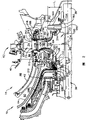
Fig. 2 is the cross sectional representation of the turbine cooling circuit that uses with gas turbine engine shown in Figure 1.
Embodiment
Fig. 1 is the schematic representation of gas turbine engine 10, and it comprises a gear-box 12, a high pressure compressor 14 and a firing chamber 16.Motor 10 also comprises a high-pressure turbine 18 and a low-pressure turbine 20.Gear-box 12 is connected by first axle 24 with turbine 20, and compressor 14 is connected by second axle 26 with turbine 18.Because axle 24 and 26 is coaxillay aligned basically, so each root axle all rotates round identical rotational axis 28.In one embodiment, gas turbine engine is the Ohio, the city of Cincinnati, the LV100 that General Electric Co. Limited sells.
In the work, air flows by compressor 14.The air of high compression is delivered to firing chamber 16.Before discharging from gas turbine engine 10,16 the air stream drives turbine 18 and 20 from the firing chamber.The merit that turbine 20 is done and 24 pass to gear-box 12 with axle, in gear-box 12, the merit that is had is utilized to drive automobile or generator.
Fig. 2 is the schematic cross section of the turbine cooling circuit 38 that can use with gas turbine engine 10.Firing chamber 16 comprises the neck bush 42 of 40, one annulars of external bushing of an annular, and the terminal (not shown) of a dome shape that extends between external bushing 40 and neck bush 42.External bushing 40 and neck bush 42 inwardly separate along radial direction from the burning chamber shell (not shown), and form a burning cavity system component 46.Interior nozzle supporting 44 is essentially annular, and extends downstream from the diffuser (not shown).Burning cavity 46 is essentially annular shape, and forms between lining 40 and 42.Neck bush 42 and interior nozzle supporting 44 constitute inner passage 50.Each extends to the turbine nozzle 52 that is placed on 16 downstreams, firing chamber external bushing 40 and neck bush 42.
High-pressure turbine 18 basically with 14 coaxial connections (as shown in Figure 1) of compressor, and in the firing chamber 16 downstream.Turbine 18 comprises a rotor assembly 62, and it comprises at least one rotor 64 that is made of one or more disks 66.In the exemplary embodiment, disk 66 comprises radially inner wheel hub 70 of 68, one of outward edges radially, and generally radially extends between them, and a whole disc 72 that radially extends internally from corresponding blade dovetail groove 73.Each disk 66 also comprises a plurality of radially from outward edge 68 outward extending blades 74.Disk 66 extends at circumferencial direction round rotor assembly 62, and each row's blade is sometimes referred to as the level of a turbine.
The disc seat 82 at the disc seat 80 of an annular front portion and the rear portion of an annular extends along dovetail groove 73, so that rotor blade 74 is remained in the dovetail groove 73.Specifically, anterior disc seat 80 extends along the upstream side 84 of disk 66, and comprise 110, one of outer ends radially radially the inner 112 and a body 114 that between them, extends.Body 114 comprises a plurality of external sealed tooth 120 and a plurality of radially interior sealing teeth 122 radially.Radially external sealed tooth 120 and Sealing 124 cooperations form an outer equalizing piston (OBP) sealing 126; And inwardly sealing tooth 122 and Sealing 128 cooperations of footpath form an inner equilibrium piston (I BP) sealing 130.Between IBP sealing 130 and OBP sealing 126, form the discharge chamber 134 of accelerating unit, and OBP sealing 126 is placed between cooling chamber 134 and the outer equalizing piston discharge chamber 138.
Rear portion disc seat 82 extends along the downstream side 150 of disk 66, and comprises 152, one radial inner end 154 of a radial outer end, and an individuality 156 that extends between them.Body 156 comprises 160, one disk minor axises of cooling plate part part 162, and a plurality of air pump feeder 164 radially that is placed between them.Cooling plate part 160 is connected on the disk 66 with the radius press fit, and extends to each air pump feeder 164 radially from the outer end 156 of seat ring.The direction of disk minor axis part 162 is vertical with seat ring part 160 basically, and extends along rotor shaft 26.More particularly, disk minor axis part 162 extends to seat ring end 154 from air pump feeder 164 radially, so that the disc seat 82 at rear portion can be connected with axle 26, makes compression load reach seat ring 82 by shaft portion 162.
In motor 10, air pump feeder 164 radially is spaced-apart on circumference, and the direction of each pump feeder is all vertical with rotational axis 28 basically.In the exemplary embodiment, the disc seat 82 at rear portion comprises 8 air pump feeders 164 radially.Each air pump feeder 164 radially all is hollow, and comprises 180, one of inlets radially in the outlet 182 of inlet 182 outsides, and of extending between them is essentially columniform body 184.Each air pump feeder 164 length radially is L
1, the disc seat 82 that it can make each pump feeder 164 stretch at least in part at least in part with the rear portion is in the rear part edge chamber 188 on border.In addition, the length L of radial air pump feeder
1Also can be convenient to keep or quicken to flow through pump feeder 164 air angular velocity and increase this air with respect to more weak forced vortex pressure and high discharge pressure.This forced vortex pressure raises and can produce when not using pump feeder 164.
Each air pump feeder inlet 180 radially, connected relation is connected with a vestibule 190 to flow.Vestibule 190 forms between disk 66 and axle 26 at least in part.Vestibule 190 radially each radially air pump feeder 164 and buffer oil storage vallecular cavity 194 between extend; And with the circulation connected relation be connected with buffer oil storage vallecular cavity 194 with each air pump feeder 164 radially.Buffer oil storage vallecular cavity 194 is connected with air source with the connected relation that flows also by annular space 196, feasible air with annular space 196 discharges, in being expelled to oil storage tank 200 before, enter in the buffer oil storage vallecular cavity 194.As following illustrating in greater detail, go into the vestibule 190 from the leakage flow of buffer oil storage vallecular cavity 194.
Specifically, the air that at least a portion compressor 14 is extracted out, in the discharge chamber 134 that is expelled to accelerating unit before, flow through accelerating unit.The cooling air of being supplied with by buffer oil storage vallecular cavity 194 209 feeds in the oil storage tank 200.Deliver to the part 202 of the air 210 in buffer chamber 194, mix with the air 214 that leaks by IBP sealing 130 from discharge side 134, and feed in the vestibule 190.From the leakage of the air 212 of buffer oil storage vallecular cavity 194, be convenient to prevent that warm compressor exhausting air from sucking in the oil storage tank 200.More particularly, because the air 214 that flows in the vestibule 190 is discharged by pump feeder 164, therefore, the working pressures in the vestibule 190 reduce, and make pump feeder 164 be convenient to clean cavity 190 for certain and prevent and reciprocally flow 212.In addition, increase because flow through the head pressure of the air 214 of pump feeder 164, therefore, pump feeder 164 also is certain to be convenient to clean the chamber, edge 188 at rear portion.
Flowing of discharging from rear part edge chamber 188 216 is forced to and radially outwards enters between the buffer sealing 218 that a disk black box 82 and rear portion transmitting catheter internal flow pass through, so that cooled rotor outward edge 68 and disk black box 82.In addition, the anti-discharge gas that sucks warm compressor of going up is convenient in chamber 190 and 188 cleaning.This gas can cause to be placed on inner face as time passes, adjacent cavities 188 and 190 or with the flow damage of the parts be communicated with of chamber 188 and 190.
Above-mentioned turbine cooling circuit is with low cost, the reliability height.This cooling circuit comprises that one makes the rear portion disc seat of an integral body with minor axis part and a plurality of radially air pump feeder.Because this seat ring and cooling plate part and the formation integrally of disk minor axis part, so manufacture cost and turbine installation time can reduce.In addition, because radially pump feeder increases the head pressure of air flowing, so pump feeder is convenient to clean rear part edge chamber and vestibule for certain, thereby guarantees to flow from the cleaning that buffer oil storage vallecular cavity comes out.Therefore, pump feeder can prevent that the warm discharge gas of compressor is inhaled in the above-mentioned cavity.As a result, the actual life that the rotator seat coil assembly at rear portion and cooling circuit can prolong the rotor assembly of turbine, with low cost, the reliability height.
Above, the exemplary embodiment of clear in detail rotor assembly and cooling circuit.Rotor assembly is not to only limit to specific embodiment described here, and the part of each assembly can use independently and dividually with other parts described here.For example, each rear portion seat assembly part also can comprehensively use with other cooling circuit parts and other rotor assembly.
Though utilized specific embodiment that the present invention has been described, the people who is skilled in technique knows that in the spirit and scope of claims, the present invention can make improvements.
Claims (10)
1. the method for an assembling gas turbine engine (10), described method comprises the steps:
A rotor assembly (62) that comprises a rotor shaft (26) and a rotor discs (66) is provided; This rotor discs comprises an outward edge (68) radially, a wheel hub (70) and a whole disc (72) that extends between them radially; Wherein, this rotor assembly can rotate around the rotational axis (28) that passes this rotor shaft,
It is characterized in that,
The disc seat (82) that will comprise at least one discharge pipe (164) is connected with this rotor discs, and wherein, this discharge pipe is protruding from this disc seat, is used for pumping on the direction vertical with rotational axis, discharges cooling fluid then.
2. the method for claim 1, it is characterized by, the disc seat (82) that will comprise at least one discharge pipe (164) also comprises with rotor discs (66) step of connecting: disc seat is connected with this rotor discs, makes that this at least one discharge pipe is positioned between rear portion cooling plate (160) and the integrally formed disk minor axis (162).
3. method as claimed in claim 2, it is characterized by, disc seat (82) is also comprised with rotor discs (66) step of connecting: this disc seat is connected with rotor discs, this rear portion cooling plate (160) is connected by on this rotor discs disc (72), and make this disk minor axis be connected with this rotor shaft.
4. method as claimed in claim 2, it is characterized by, the disc seat (82) that will comprise at least one discharge pipe (164) also comprises with this rotor discs step of connecting: this disc seat is connected with this rotor discs, makes this at least one discharge pipe be connected with the vestibule (190) that is limited by the radially inner wheel hub (70) of this rotor discs at least in part by the connected relation that flows.
5. method as claimed in claim 2, it is characterized by, will comprise that the disc seat (82) of at least one discharge pipe (164) also comprises with this rotor discs (66) step of connecting: a circular disk seat is connected with comprising a plurality of rotor discs round rotor shaft (26) along the discharge pipe of circle spacing.
6. rotor assembly (62) that comprises the gas turbine engine (10) of single-revolution central axis, described rotor assembly comprises:
One roots rotor axle (26);
A rotor discs (66), it is connected with described rotor shaft, and comprises an outward edge (68) radially, one radially inner wheel hub (70) and the disc (72) of an integral body of between them, extending,
It is characterized in that,
Described rotor assembly also comprises a disc seat (82), it is connected with described rotor discs, and comprise that at least one is stretched out from described disc seat radially outward, be used for discharging along the direction pumping vertical, then the discharge pipe (164) of cooling fluid with the rotational axis (28) of this gas turbine engine.
7. rotor assembly as claimed in claim 6 (62), it is characterized by, it also comprises a cooling circuit (38) that flows and be communicated with disc seat discharge pipe (164), described cooling circuit is supplied with described at least one discharge pipe with the air of emitting, and described at least one discharge pipe discharged cooling fluid to the downstream of the radially outward edge (68) of described rotor discs.
8. rotor assembly as claimed in claim 6 (62), it is characterized by, described disc seat (82) also comprises the rear portion cooling plate (160) of a disk minor axis (162) and an integral body, described at least one discharge pipe is between described disk minor axis and described rear portion cooling plate, and described disk minor axis is connected with described rotor shaft (26).
9. rotor assembly as claimed in claim 6 (62), it is characterized by, it also comprises one by mobile connected relation and a cooling fluid source, the cooling circuit (38) that vestibule (190) is connected with described at least one discharge pipe (164), described vestibule is limited by described rotor discs wheel hub (70) at least in part, and described at least one discharge pipe is used for from (190) pumping of described vestibule and discharges cooling fluid then.
10. rotor assembly as claimed in claim 9 (62) is characterized by, and described at least one discharge pipe (164) is convenient to discharge cooling fluid with positive pressure to the downstream of the radially outward edge (68) of described rotor discs.
Applications Claiming Priority (2)
| Application Number | Priority Date | Filing Date | Title |
|---|---|---|---|
| US10/656,599 US6910852B2 (en) | 2003-09-05 | 2003-09-05 | Methods and apparatus for cooling gas turbine engine rotor assemblies |
| US10/656599 | 2003-09-05 |
Publications (2)
| Publication Number | Publication Date |
|---|---|
| CN1590733A CN1590733A (en) | 2005-03-09 |
| CN100404816C true CN100404816C (en) | 2008-07-23 |
Family
ID=34136709
Family Applications (1)
| Application Number | Title | Priority Date | Filing Date |
|---|---|---|---|
| CNB2004100634658A Active CN100404816C (en) | 2003-09-05 | 2004-07-05 | Methods and apparatus for cooling gas turbine engine rotor assemblies |
Country Status (5)
| Country | Link |
|---|---|
| US (1) | US6910852B2 (en) |
| EP (1) | EP1512843B1 (en) |
| JP (1) | JP4559141B2 (en) |
| CN (1) | CN100404816C (en) |
| BR (1) | BRPI0402669A (en) |
Families Citing this family (27)
| Publication number | Priority date | Publication date | Assignee | Title |
|---|---|---|---|---|
| DE102005027890B4 (en) * | 2005-06-16 | 2007-05-03 | Man Diesel Se | Exhaust gas turbocharger for an internal combustion engine |
| FR2892454B1 (en) * | 2005-10-21 | 2008-01-25 | Snecma Sa | DEVICE FOR VENTILATION OF TURBINE DISCS IN A GAS TURBINE ENGINE |
| US7458774B2 (en) * | 2005-12-20 | 2008-12-02 | General Electric Company | High pressure turbine disk hub with curved hub surface and method |
| US20080080972A1 (en) * | 2006-09-29 | 2008-04-03 | General Electric Company | Stationary-rotating assemblies having surface features for enhanced containment of fluid flow, and related processes |
| US8016552B2 (en) * | 2006-09-29 | 2011-09-13 | General Electric Company | Stator—rotor assemblies having surface features for enhanced containment of gas flow, and related processes |
| US7967559B2 (en) * | 2007-05-30 | 2011-06-28 | General Electric Company | Stator-rotor assembly having surface feature for enhanced containment of gas flow and related processes |
| US8506660B2 (en) * | 2007-09-12 | 2013-08-13 | General Electric Company | Nozzles for use with gasifiers and methods of assembling the same |
| US8240974B2 (en) * | 2008-03-21 | 2012-08-14 | United Technologies Corporation | Cold air buffer supply tube |
| JP4929217B2 (en) * | 2008-03-28 | 2012-05-09 | 三菱重工業株式会社 | Gas turbine, gas turbine intermediate shaft, and gas turbine compressor cooling method |
| US8277170B2 (en) * | 2008-05-16 | 2012-10-02 | General Electric Company | Cooling circuit for use in turbine bucket cooling |
| GB201015028D0 (en) * | 2010-09-10 | 2010-10-20 | Rolls Royce Plc | Gas turbine engine |
| US8740554B2 (en) | 2011-01-11 | 2014-06-03 | United Technologies Corporation | Cover plate with interstage seal for a gas turbine engine |
| US8662845B2 (en) | 2011-01-11 | 2014-03-04 | United Technologies Corporation | Multi-function heat shield for a gas turbine engine |
| US8840375B2 (en) | 2011-03-21 | 2014-09-23 | United Technologies Corporation | Component lock for a gas turbine engine |
| ITCO20110013A1 (en) * | 2011-03-29 | 2012-09-30 | Nuovo Pignone Spa | LOCKING SYSTEMS FOR TURBO-EXTRACTORS TO BE USED IN ORGANIC RANKINE CYCLES |
| US9062566B2 (en) * | 2012-04-02 | 2015-06-23 | United Technologies Corporation | Turbomachine thermal management |
| US9234463B2 (en) | 2012-04-24 | 2016-01-12 | United Technologies Corporation | Thermal management system for a gas turbine engine |
| CN103707062B (en) * | 2012-12-26 | 2016-08-17 | 浙江金浪动力有限公司 | A kind of multifunctional engine assembly bench |
| CN103056653B (en) * | 2013-01-11 | 2015-12-02 | 沈阳黎明航空发动机(集团)有限责任公司 | A kind of bracket type core machine assembly method |
| EP2787169A1 (en) * | 2013-04-04 | 2014-10-08 | MTU Aero Engines GmbH | Rotor for a turbo engine |
| CN103899367B (en) * | 2014-02-14 | 2015-07-29 | 哈尔滨工业大学 | The stacking assembly method of aeroengine rotor and device |
| CN103790651B (en) * | 2014-02-14 | 2015-07-29 | 哈尔滨工业大学 | Air supporting and magnetic float the aeroengine rotor assembly method and device that combine |
| US10316681B2 (en) * | 2016-05-31 | 2019-06-11 | General Electric Company | System and method for domestic bleed circuit seals within a turbine |
| US10539035B2 (en) * | 2017-06-29 | 2020-01-21 | General Electric Company | Compliant rotatable inter-stage turbine seal |
| US10947993B2 (en) | 2017-11-27 | 2021-03-16 | General Electric Company | Thermal gradient attenuation structure to mitigate rotor bow in turbine engine |
| US11674395B2 (en) * | 2020-09-17 | 2023-06-13 | General Electric Company | Turbomachine rotor disk with internal bore cavity |
| US11879411B2 (en) | 2022-04-07 | 2024-01-23 | General Electric Company | System and method for mitigating bowed rotor in a gas turbine engine |
Citations (6)
| Publication number | Priority date | Publication date | Assignee | Title |
|---|---|---|---|---|
| US4541774A (en) * | 1980-05-01 | 1985-09-17 | General Electric Company | Turbine cooling air deswirler |
| US4882902A (en) * | 1986-04-30 | 1989-11-28 | General Electric Company | Turbine cooling air transferring apparatus |
| DE3310529A1 (en) * | 1982-03-23 | 1996-10-31 | Snecma | Device for cooling the rotor of a gas turbine |
| CN1169174A (en) * | 1995-11-24 | 1997-12-31 | 三菱重工业株式会社 | Heat-recovery gas turbine rotor |
| CN1225704A (en) * | 1996-05-17 | 1999-08-11 | 西屋电气公司 | Turbomachine rotor cooling |
| JP2002054459A (en) * | 2000-07-14 | 2002-02-20 | General Electric Co <Ge> | Method and device for feeding cooling air flow to turbine engine |
Family Cites Families (12)
| Publication number | Priority date | Publication date | Assignee | Title |
|---|---|---|---|---|
| US4086757A (en) * | 1976-10-06 | 1978-05-02 | Caterpillar Tractor Co. | Gas turbine cooling system |
| US4190398A (en) * | 1977-06-03 | 1980-02-26 | General Electric Company | Gas turbine engine and means for cooling same |
| US4309147A (en) | 1979-05-21 | 1982-01-05 | General Electric Company | Foreign particle separator |
| US4890981A (en) * | 1988-12-30 | 1990-01-02 | General Electric Company | Boltless rotor blade retainer |
| US5236302A (en) * | 1991-10-30 | 1993-08-17 | General Electric Company | Turbine disk interstage seal system |
| US5288210A (en) * | 1991-10-30 | 1994-02-22 | General Electric Company | Turbine disk attachment system |
| US5226785A (en) * | 1991-10-30 | 1993-07-13 | General Electric Company | Impeller system for a gas turbine engine |
| US5472313A (en) * | 1991-10-30 | 1995-12-05 | General Electric Company | Turbine disk cooling system |
| US5275534A (en) * | 1991-10-30 | 1994-01-04 | General Electric Company | Turbine disk forward seal assembly |
| US5555721A (en) * | 1994-09-28 | 1996-09-17 | General Electric Company | Gas turbine engine cooling supply circuit |
| JPH10238301A (en) * | 1997-02-21 | 1998-09-08 | Mitsubishi Heavy Ind Ltd | Cooling passage of gas turbine blade |
| US6331097B1 (en) * | 1999-09-30 | 2001-12-18 | General Electric Company | Method and apparatus for purging turbine wheel cavities |
-
2003
- 2003-09-05 US US10/656,599 patent/US6910852B2/en not_active Expired - Lifetime
-
2004
- 2004-06-30 EP EP04253920.5A patent/EP1512843B1/en not_active Expired - Fee Related
- 2004-07-02 BR BR0402669-1A patent/BRPI0402669A/en not_active IP Right Cessation
- 2004-07-05 CN CNB2004100634658A patent/CN100404816C/en active Active
- 2004-07-05 JP JP2004197762A patent/JP4559141B2/en not_active Expired - Fee Related
Patent Citations (6)
| Publication number | Priority date | Publication date | Assignee | Title |
|---|---|---|---|---|
| US4541774A (en) * | 1980-05-01 | 1985-09-17 | General Electric Company | Turbine cooling air deswirler |
| DE3310529A1 (en) * | 1982-03-23 | 1996-10-31 | Snecma | Device for cooling the rotor of a gas turbine |
| US4882902A (en) * | 1986-04-30 | 1989-11-28 | General Electric Company | Turbine cooling air transferring apparatus |
| CN1169174A (en) * | 1995-11-24 | 1997-12-31 | 三菱重工业株式会社 | Heat-recovery gas turbine rotor |
| CN1225704A (en) * | 1996-05-17 | 1999-08-11 | 西屋电气公司 | Turbomachine rotor cooling |
| JP2002054459A (en) * | 2000-07-14 | 2002-02-20 | General Electric Co <Ge> | Method and device for feeding cooling air flow to turbine engine |
Also Published As
| Publication number | Publication date |
|---|---|
| US6910852B2 (en) | 2005-06-28 |
| EP1512843B1 (en) | 2016-03-09 |
| EP1512843A2 (en) | 2005-03-09 |
| US20050053464A1 (en) | 2005-03-10 |
| CN1590733A (en) | 2005-03-09 |
| BRPI0402669A (en) | 2005-05-24 |
| JP4559141B2 (en) | 2010-10-06 |
| EP1512843A3 (en) | 2012-03-14 |
| JP2005083375A (en) | 2005-03-31 |
Similar Documents
| Publication | Publication Date | Title |
|---|---|---|
| CN100404816C (en) | Methods and apparatus for cooling gas turbine engine rotor assemblies | |
| CN101178014B (en) | Dual interstage cooled engine | |
| EP1825149B1 (en) | Multi-stage compressor and housing therefor | |
| CN1892000B (en) | Igniter tube and method of assembling same | |
| EP1091089B1 (en) | Cooling air supply through bolted flange assembly | |
| CN102076940B (en) | Gas turbine and method of operating gas turbine | |
| CN100404818C (en) | Methods and apparatus to reduce seal rubbing within gas turbine engines | |
| RU2417322C2 (en) | Device for ventilation of gas turbine engine wheel disks, gas turbine engine | |
| US8668437B1 (en) | Turbine engine cooling fluid feed system | |
| US4759688A (en) | Cooling flow side entry for cooled turbine blading | |
| CN106574556B (en) | Gas turbine | |
| RU2011120176A (en) | HIGH PRESSURE TURBINE VENTILATION IN A GAS-TURBINE ENGINE | |
| JP2012082822A (en) | Inducer for gas turbine system | |
| CN101960092A (en) | Turbine disc and gas turbine | |
| CN105408692B (en) | Has standoff heat shield | |
| US6361270B1 (en) | Centrifugal pump for a gas turbine engine | |
| US10125632B2 (en) | Wheel space purge flow mixing chamber | |
| US6769870B2 (en) | Structure for separating the high and low pressure turboexpanders of a gas turbine | |
| CN104948300A (en) | Combustion gas turbine | |
| CN100549366C (en) | The turbine stator protective gear | |
| JP3858436B2 (en) | Multistage compressor structure | |
| US10132195B2 (en) | Wheel space purge flow mixing chamber | |
| RU2176331C1 (en) | Gas-turbine engine compressor | |
| US6494673B2 (en) | Turbine engine | |
| JP2003003859A (en) | Cycle turbine engine |
Legal Events
| Date | Code | Title | Description |
|---|---|---|---|
| C06 | Publication | ||
| PB01 | Publication | ||
| C10 | Entry into substantive examination | ||
| SE01 | Entry into force of request for substantive examination | ||
| C14 | Grant of patent or utility model | ||
| GR01 | Patent grant |