CN100404373C - Overhead luggage storage compartment for an aircraft - Google Patents
Overhead luggage storage compartment for an aircraft Download PDFInfo
- Publication number
- CN100404373C CN100404373C CNB028229320A CN02822932A CN100404373C CN 100404373 C CN100404373 C CN 100404373C CN B028229320 A CNB028229320 A CN B028229320A CN 02822932 A CN02822932 A CN 02822932A CN 100404373 C CN100404373 C CN 100404373C
- Authority
- CN
- China
- Prior art keywords
- storage box
- connecting element
- box according
- reinforcement structure
- aircraft
- Prior art date
- Legal status (The legal status is an assumption and is not a legal conclusion. Google has not performed a legal analysis and makes no representation as to the accuracy of the status listed.)
- Expired - Fee Related
Links
Images


Classifications
-
- B—PERFORMING OPERATIONS; TRANSPORTING
- B64—AIRCRAFT; AVIATION; COSMONAUTICS
- B64D—EQUIPMENT FOR FITTING IN OR TO AIRCRAFT; FLIGHT SUITS; PARACHUTES; ARRANGEMENT OR MOUNTING OF POWER PLANTS OR PROPULSION TRANSMISSIONS IN AIRCRAFT
- B64D11/00—Passenger or crew accommodation; Flight-deck installations not otherwise provided for
- B64D11/003—Stowage devices for passengers' personal luggage
-
- B—PERFORMING OPERATIONS; TRANSPORTING
- B61—RAILWAYS
- B61D—BODY DETAILS OR KINDS OF RAILWAY VEHICLES
- B61D37/00—Other furniture or furnishings
- B61D37/003—Other furniture or furnishings luggage rack and umbrella-stand for rail vehicles
-
- Y—GENERAL TAGGING OF NEW TECHNOLOGICAL DEVELOPMENTS; GENERAL TAGGING OF CROSS-SECTIONAL TECHNOLOGIES SPANNING OVER SEVERAL SECTIONS OF THE IPC; TECHNICAL SUBJECTS COVERED BY FORMER USPC CROSS-REFERENCE ART COLLECTIONS [XRACs] AND DIGESTS
- Y02—TECHNOLOGIES OR APPLICATIONS FOR MITIGATION OR ADAPTATION AGAINST CLIMATE CHANGE
- Y02T—CLIMATE CHANGE MITIGATION TECHNOLOGIES RELATED TO TRANSPORTATION
- Y02T50/00—Aeronautics or air transport
- Y02T50/40—Weight reduction
Landscapes
- Engineering & Computer Science (AREA)
- Aviation & Aerospace Engineering (AREA)
- Mechanical Engineering (AREA)
- Vehicle Step Arrangements And Article Storage (AREA)
- Seats For Vehicles (AREA)
- Rigid Containers With Two Or More Constituent Elements (AREA)
Abstract
Description
技术领域 technical field
本发明涉及一种特别用于飞机的高架行李存放箱,包括至少一个与存放箱连接的加强结构,该加强结构基本上沿存放箱的纵向延伸的方向设置,并且包括至少一个用于悬挂在飞机或类似物的一个承载结构上的装置。The invention relates to an overhead luggage storage box, especially for an aircraft, comprising at least one reinforcement structure connected to the storage box, the reinforcement structure being arranged substantially in the direction of the longitudinal extension of the storage box, and comprising at least one or similar device on a load-bearing structure.
背景技术 Background technique
高架行李存放箱特别在飞机中用于在飞行期间保存旅客的手提行李。不过本发明也涉及其他的运输工具,例如在轨道上行驶的车辆,特别是高速列车以及公共汽车或船舶的高架存放箱。高架行李存放箱在飞机中特别在起飞阶段和着陆阶段以及在飞行时期和非常时刻受到很高的机械载荷,因此飞机用的高架行李存放箱必须针对特高的载荷来设计。对行李存放箱的这样高的要求明显提高制造费用并且大多还包括自重的增加。Overhead luggage storage bins are used in particular in aircraft to store passenger's hand luggage during a flight. However, the invention also relates to other means of transport, such as vehicles traveling on rails, in particular high-speed trains and overhead storage boxes for buses or ships. Overhead luggage storage boxes are subjected to high mechanical loads in aircraft, especially during the take-off and landing phases, as well as during flight and emergency moments, so overhead luggage storage boxes for aircraft must be designed for particularly high loads. Such high demands on the luggage storage case significantly increase the manufacturing costs and generally also include an increase in the own weight.
特别是用于飞机的高架行李存放箱如今大多由塑料制成多层结构,其中芯部一般由蜂窝状结构材料构成而由塑料的覆盖层覆盖,该塑料可用玻璃纤维或碳纤维加强。高架行李存放箱可由一弯边围绕的凹槽构成,其由上述材料通过多次弯曲或折叠制成。存放箱还可以在一热压锅中通过设置在一模具上的各预浸层的时效硬化来制造。并且存放箱大多包括一开口,其有利地可由一翻盖关闭。例如EP 0 557 267 B1描述了一种这样的高架行李存放箱和其制造的方法。由于行李存放箱的基本上垂直的侧壁受到由垂直定向的力引起的高载荷,这些侧壁和其与弯边围绕的凹槽的连接必须特别稳定地和耗费很大地制造。这一方面增加行李存放箱的重量而另一方面提高制造成本。Overhead luggage storage boxes, especially for aircraft, are nowadays mostly made of plastic in multilayer construction, the core usually consisting of a honeycomb structure material covered by a cover layer of plastic, which can be reinforced with glass fibers or carbon fibers. The overhead luggage storage box may consist of a groove surrounded by a bent edge made of the material described above by multiple bending or folding. The storage box can also be produced in an autoclave by age curing of the prepreg layers arranged on a mould. And storage boxes usually comprise an opening, which can advantageously be closed by a flap. For example EP 0 557 267 B1 describes a kind of such overhead luggage storage box and the method for its manufacture. Since the substantially vertical side walls of the luggage storage box are subjected to high loads caused by vertically oriented forces, these side walls and their connection to the groove surrounded by the bead must be produced particularly stably and with great effort. This increases the weight of the luggage storage box on the one hand and increases the manufacturing costs on the other hand.
EP 0 658 644 A2也描述了一种高架行李存放箱,其由多个构件制成,它们具有特别小的重量而同时高的稳定性。EP 0 658 644 A2 also describes an overhead luggage storage box, which is made of several components, which have a particularly low weight and at the same time high stability.
EP 718 189 A1公开一种具有较高承载能力的高架行李存放箱,其打算用于改进现有的飞机并因此与现有的高架行李存放箱的悬挂装置相适应。不过按照该文件的高架行李存放箱不是专为位于其中的行李物件的较高的静载荷设计的。EP 718 189 A1 discloses an overhead luggage storage box with a relatively high load carrying capacity, which is intended for retrofitting existing aircraft and is therefore compatible with existing overhead luggage storage box suspension arrangements. However, the overhead luggage storage box according to this document is not designed for the high static load of the luggage items contained therein.
特别用于飞机的旅客行李等的高架行李存放箱通常在机械上根据两种情况设计。一种情况由正常的正规飞行操作形成,其中存放箱应该经受得住规定的载荷,例如因阵风,特别是在起飞和着陆时期引起的载荷而不损坏。在起飞、着陆的情况下或由阵风通过处于行李存放箱中的载荷的惯性产生一加速度,该加速度可能高达重力加速度的6倍。这样的数值特别是在飞机的尾部或头部是惯常的。第二种载荷情况由一种紧急情况形成,例如其可能发生在飞机的紧急着陆或坠落的情况下。为了在这样的情况下可以确保旅客的安全,行李存放箱通常根据正常载荷的1.5倍设计,亦即例如根据9倍的重力加速度数值的载荷来设计。这样高的载荷需要行李存放箱的特高的制造费用,特别是在侧壁和其与高架行李存放箱的弯边围绕的凹槽的连接的方面。Overhead luggage storage boxes, especially for passenger luggage etc. of aircraft, are usually designed mechanically according to two situations. One situation arises from normal regular flight operations in which the stowage box should withstand specified loads, for example due to wind gusts, especially during take-off and landing, without damage. During take-off, landing or due to a gust of wind passing through the inertia of the load in the luggage compartment, an acceleration occurs which can be up to 6 times the acceleration due to gravity. Such values are customary especially at the tail or nose of the aircraft. The second load situation results from an emergency situation, which may occur, for example, in the event of an emergency landing or crash of the aircraft. In order to ensure the safety of passengers in such cases, luggage storage boxes are usually designed for a load of 1.5 times the normal load, that is to say for example a load of 9 times the value of the acceleration due to gravity. Such high loads necessitate particularly high production costs of the luggage storage box, especially with regard to the side walls and their connection to the grooves surrounded by the flanges of the overhead luggage storage box.
如今越来越多的和越来越重的行李物件如手提箱、笔记本电脑、照相和摄像设备等作为手提行李随带于机舱中。实际上常常超过了行李存放箱的许用的总载荷。在紧急情况下,例如在紧急着陆时处于存放箱中的行李物件可能构成对旅客的危险。为了加强高架行李存放箱的底板大多将特别是以型材的形式的加强结构固定在底板上,其同时例如用于悬挂位于旅客座位排列的上方的如通风、供氧和照明的装置。借此虽然通过加强结构加强了高架行李存放箱的底板,不过出现的力传入存放箱的侧壁并由那里传入悬挂装置并且继续传入飞机等的承载结构中。在这种情况下其可能导致侧壁的损坏并从而导致高架行李存放箱的开口和一个行李物件的掉落或导致在飞机的承载结构上撕下悬挂装置。Nowadays more and more and heavier luggage items such as suitcases, notebook computers, camera and video equipment etc. are carried in the cabin as hand luggage. In fact, the permissible total load of the luggage storage compartment is often exceeded. In an emergency situation, such as during an emergency landing, items of luggage in the stowage compartment may pose a danger to passengers. In order to reinforce the floor of the overhead storage box, reinforcing structures, in particular in the form of profiles, are usually fastened to the floor, which at the same time are used, for example, to suspend devices such as ventilation, oxygen supply and lighting above the passenger seating arrangement. Although the floor of the overhead luggage storage box is thus reinforced by the reinforcing structure, the forces that occur are transmitted to the side walls of the storage box and from there to the suspension and on to the load-bearing structure of the aircraft or the like. In this case it can lead to damage to the side walls and thus to the opening of the overhead luggage compartment and a luggage item to fall or to tearing off the suspension on the load-bearing structure of the aircraft.
为了保护高架行李存放箱以防掉落,已知例如以柔性的力转向元件的形式的安全装置,其还包括用于消除运动能的装置,其即使在悬挂装置撕下以后高架行李存放箱仍固定在飞机等的承载结构上。一种这样的安全装置例如描述于EP 0 767 100 A1中。In order to protect the overhead luggage storage box against falling, safety devices are known, for example in the form of flexible force deflecting elements, which also comprise means for dissipating the kinetic energy, which even after the suspension device has been torn off, the overhead luggage storage box remains Fastened to load-bearing structures such as aircraft. One such safety device is described, for example, in EP 0 767 100 A1.
发明内容 Contents of the invention
本发明的目的在于,提供一种特别用于飞机的高架行李存放箱,其经受住由处于其中的行李物件引起的静载荷并从而对坐在行李存放箱下方的旅客没有任何的危险。此外,高架行李存放箱应可以尽可能快速、简单和廉价地制造并具有尽可能小的重量。小重量对于飞机由于燃料消耗是特别重要的。The object of the present invention is to provide an overhead luggage storage box, in particular for aircraft, which withstands the static loads caused by the luggage items contained therein and thus does not present any danger to passengers sitting under the luggage storage box. Furthermore, the overhead luggage storage box should be able to be produced as quickly, simply and inexpensively as possible and have the lowest possible weight. Low weight is especially important for aircraft due to fuel consumption.
本发明的目的这样来达到,即在加强结构与悬挂装置之间在存放箱的侧面分别相对于存放箱的纵向延伸基本上垂直设置至少一个刚性的连接元件。本发明的刚性连接元件用作为从存放箱的底板经由加强结构或各加强结构向悬挂结构或各悬挂结构的力转向元件,借此减轻高架行李存放箱,特别是其侧壁的负担并从而可以较简单和较廉价地制造。特别是因此对高架行李存放箱的侧壁与其余的存放箱体之间的连接没有高的要求。所谓刚性的连接元件应该理解为连接元件由在正常条件的载荷作用下没有遭受任何重要的形状变化的材料制成。通过在加强结构与悬挂结构之间设置的刚性连接元件,高架行李存放箱可以经受住较高的静载荷。另一方面对高架行李存放箱的制造和组装提出较低的要求。连接元件的数目匹配于最大的出现的载荷值。借此将高架行李存放箱本身的静载荷转入加强结构和连接元件中。因此保护位于高架行李存放箱下方的旅客等免受存放箱或行李物件特别是在极端情况下掉落的危险。所谓“基本上垂直”应该理解为相对于高架行李存放箱的纵向方向的垂直线±5°的角度范围。为了进一步提高安全性,例如在极端情况下的动载荷情况时,自然可以采用安全装置,例如以上所述的以安全带等的形式的安全装置。本发明不仅适用于固定的高架行李存放箱而且适用于可转动地或可移动地设置的存放箱。在可转动设置的高架行李存放箱中刚性的连接元件不仅设置在可动的存放箱部件的侧面而且设置在与可动的存放箱部件可能连接的固定的存放箱的侧面。The object of the invention is achieved in that at least one rigid connecting element is arranged substantially perpendicularly to the longitudinal extension of the storage box between the reinforcement structure and the suspension device on the sides of the storage box. The rigid connection element according to the invention serves as a force deflection element from the floor of the storage box via the reinforcement structure or reinforcement structures to the suspension structure or suspension structures, thereby relieving the overhead luggage storage box, in particular its side walls, and thus making it possible Simpler and cheaper to manufacture. In particular, no high demands are placed on the connection between the side walls of the overhead luggage storage box and the rest of the storage box. By a rigid connecting element is understood a connecting element made of a material which does not undergo any significant change in shape under normal conditions of loading. Through the rigid connection elements provided between the reinforcement structure and the suspension structure, the overhead luggage storage box can withstand high static loads. On the other hand, lower requirements are placed on the manufacture and assembly of the overhead luggage storage box. The number of connecting elements is matched to the largest occurring load value. This transfers the static load of the overhead luggage storage box itself into the reinforcement structure and connecting elements. Passengers or the like located under the overhead luggage storage box are thus protected against the risk of the storage box or luggage items falling, especially in extreme cases. The so-called "substantially vertical" should be understood as an angle range of ±5° relative to the vertical line of the longitudinal direction of the overhead luggage storage box. To further increase safety, for example in extreme dynamic load situations, it is of course possible to use safety devices, for example in the form of seat belts or the like as described above. The invention is suitable not only for fixed overhead luggage storage boxes but also for rotatably or movably arranged storage boxes. In the case of a rotatably arranged overhead luggage storage box, the rigid connecting elements are arranged not only on the side of the movable storage box part but also on the side of the fixed storage box to which the movable storage box part may be connected.
优选连接元件与加强结构和悬挂装置形锁合连接。通过形锁合确保从存放箱经由加强结构向基本上垂直设置的连接元件并从那里继续向悬挂装置和向飞机等的承载结构的力传递。Preferably, the connecting element is positively connected to the reinforcing structure and the suspension. The force transmission from the storage box via the reinforcing structure to the substantially vertically arranged connecting element and from there to the suspension device and to the load-bearing structure of the aircraft or the like is ensured by the form fit.
虽然高架行李存放箱可由开口的存放箱构成,但存放箱有利地包括一固定的部件和一与其可动连接的部件。Although the overhead luggage storage box may be formed from an open storage box, the storage box advantageously includes a fixed part and a part movably connected thereto.
这样的可动的存放箱部件可以由与固定的存放箱部件铰链连接的门构成。这样的实施形式在飞机的高架行李存放箱中是惯用的。Such a movable storage box part may consist of a door hingedly connected to a fixed storage box part. Such an embodiment is customary in overhead luggage storage boxes of aircraft.
对此可供选择的是,可动的存放箱部件可由一容纳行李的凹槽构成,其与固定的存放箱可动地相连接。这样的高架行李存放箱越来越多地特别应用于大型客机中,因为通过存放箱的向下转动或移动大大地便于将行李整齐地推放好。As an alternative to this, the movable storage box part can be formed by a luggage receiving recess which is movably connected to the fixed storage box. Overhead luggage storage boxes of this type are increasingly being used, in particular in large passenger aircraft, since the neat push-down of the luggage is greatly facilitated by the downward rotation or movement of the storage box.
凹槽相对于固定的存放箱部件的运动可以通过铰链来实现,其使凹槽可以相对于固定的存放箱部件转动,或通过一移动机构来实现,其使凹槽能够相对于固定的存放箱部件移动。The movement of the groove relative to the fixed storage box part can be accomplished by a hinge, which allows the groove to rotate relative to the fixed storage box part, or by a movement mechanism, which enables the groove to rotate relative to the fixed storage box part. Parts move.
可动的存放箱部件的铰链或移动机构优选与悬挂装置相连接。The hinge or movement mechanism of the movable storage box part is preferably connected to the suspension device.
按照本发明的另一特征设定,所述凹槽包括至少一个加强结构,并且在一加强结构与铰链或移动机构之间相对于存放箱的纵向延伸基本上垂直设置至少一个刚性的连接元件。因此由一凹槽构成的可动的存放箱部件以与一固定的高架行李存放箱相同的方式配备有本发明的刚性连接元件,其将静载荷由凹槽的侧壁经由连接元件和铰链或移动机构转入悬挂装置并继续转入飞机等的承载结构中。According to another characteristic of the invention it is provided that said recess comprises at least one reinforcement structure and at least one rigid connecting element is arranged substantially perpendicularly with respect to the longitudinal extension of the storage box between a reinforcement structure and the hinge or movement mechanism. The movable storage box part consisting of a groove is therefore equipped in the same way as a fixed overhead luggage storage box with the rigid connection element of the invention, which transfers the static load from the side walls of the groove via the connection element and the hinge or The mobile mechanism is transferred into the suspension and onwards into the load-bearing structure of the aircraft or the like.
通常,为了构成加强结构设置至少一个沿存放箱的纵向方向设置的并在存放箱的侧面凸出的支架。由于该支架承受高的弯曲应力,它们常常以型材的形式例如由经金属如铝制成。不过加强结构也可以具有其他的形式并由其他的材料制造。支架照例与存放箱的下面连接,例如粘合或螺钉连接。除加强存放箱外还实现承受力和力转向的功能。Usually, at least one bracket arranged in the longitudinal direction of the storage box and protruding from the side of the storage box is provided for forming the reinforcement structure. Since the supports are subjected to high bending stresses, they are often produced in the form of profiles, for example from metals such as aluminum. However, the reinforcing structure can also have other forms and be produced from other materials. The bracket is conventionally connected, for example glued or screwed, to the underside of the storage box. In addition to strengthening the storage box, it also realizes the functions of bearing force and force turning.
为了连接元件的形锁合连接,按照本发明的另一特征其具有各个开口,其中可插入加强结构和悬挂装置的端部。为了在连接元件与加强结构之间和与悬挂装置之间的形锁合连接,将加强结构和悬挂装置插入连接元件的相应的开口中是足够的。不仅沿垂直而且沿水平方向出现的力均经由连接元件传递。此外,自然可以采用固定装置,如螺钉等并从而在连接元件与支架和悬挂装置之间实现力锁合连接。然而可拆式连接具有优点,其可以很快速和简单地进行组装和拆卸并且可以例如将一飞机等较快速地例如从一客机改装成一货机。According to a further feature of the invention, for the positive connection of the connecting element, it has openings into which the reinforcing structure and the end of the suspension can be inserted. For a form-locking connection between the connecting element and the reinforcing structure and with the suspension device, it is sufficient to insert the reinforcing structure and the suspension device into corresponding openings of the connecting element. Forces occurring not only in the vertical but also in the horizontal direction are transmitted via the connecting elements. Furthermore, it is of course possible to use fastening means, such as screws or the like, and thereby achieve a force-locked connection between the connecting element and the support and the suspension. The detachable connection has the advantage, however, that it can be assembled and disassembled very quickly and easily and that, for example, an aircraft or the like can be converted relatively quickly, for example from a passenger aircraft to a cargo aircraft.
加强结构不必由单独的构件实现,而也可以由存放箱本身的一部分例如经加强的底板构成。The reinforcing structure does not have to be realized by a separate component, but can also be formed by a part of the storage box itself, for example a reinforced floor.
为了减轻连接元件的重量,其可以具有钻孔、空隙等。这些钻孔、空隙等优选设置在出现的力为最小的部位。In order to reduce the weight of the connecting element, it can have bores, recesses, etc. These bores, recesses etc. are preferably arranged at the points where the least occurring forces occur.
为了防止高架行李存放箱相对于连接元件滑动,可以将连接元件与固定的存放箱部件的或由一凹槽构成的可动的存放箱部件的侧壁相连接,例如粘合或螺钉连接。因此虽然提高组装费用,但也防止沿垂直于存放箱的纵向延伸的方向的滑动。In order to prevent the overhead luggage storage box from sliding relative to the connecting element, the connecting element can be connected, for example glued or screwed, to the side wall of the fixed storage box part or the movable storage box part formed by a groove. Although this increases the assembly effort, sliding in a direction perpendicular to the longitudinal extension of the storage box is also prevented.
侧壁优选由纤维增强的复合塑料以包括蜂窝状结构材料的芯部的多层结构构成。The side walls are preferably composed of fiber-reinforced composite plastic in a multilayer structure comprising a core of honeycomb structural material.
存放箱的各侧壁优选与固定的存放箱部件或由一凹槽构成的可动的存放箱部件粘合,其中对该连接没有高的要求。例如侧壁可以与存放箱部件一样由塑料制成多层结构并通过简单的胶接连结在一起。在侧壁与存放箱部件之间经由附加的重叠的玻璃纤维增强的塑料层的耗费的连接是不必要的。因此可以明显降低制造成本并且也减轻高架行李存放箱的重量。The side walls of the storage box are preferably glued to the fixed storage box part or the movable storage box part formed by a recess, wherein no high demands are placed on the connection. For example, the side walls can be made of plastic like the parts of the storage box in a multilayer structure and can be joined together by simple gluing. A complex connection between the side walls and the storage box part via additional overlapping layers of glass-fiber-reinforced plastic is unnecessary. The manufacturing costs can thus be significantly reduced and the weight of the overhead luggage storage box can also be reduced.
同样有可能将连接元件和加强结构成一件制成。借此构成一结构,高架行李存放箱多多少少安装在该结构上并且通过加强结构例如与存放箱的底板的连接防止横向的滑动。It is also possible to manufacture the connecting element and the reinforcing structure in one piece. This results in a structure on which the overhead luggage storage box is more or less mounted and lateral sliding is prevented by a reinforcement structure, for example a connection to the floor of the storage box.
连接元件可以由金属,优选轻金属、塑料,特别是纤维增强的塑料或通过树脂注塑法制成的塑料构成。极不同的热塑性塑料和热固性塑料适于用作塑料,其可以用玻璃纤维或碳纤维加强之。按照相应的要求选择材料。The connecting element can consist of metal, preferably light metal, plastic, in particular fiber-reinforced plastic, or plastic produced by resin injection molding. A wide variety of thermoplastics and thermosetting plastics are suitable as plastics, which can be reinforced with glass fibers or carbon fibers. Select materials according to the corresponding requirements.
为了避免在极端情况下,例如飞机的紧急着陆时高架行李存放箱的不受控的反应,连接元件包括一预定的断裂点并且与该预定的断裂点的末端连接用于消除运动能的装置。借此连接元件在超过载荷时达到预定的破坏并且通过用于消除运动能的装置避免高架行李存放箱的掉落。运动能可以例如通过一设置成环线的安全带或通过一弹性元件或通过一专门设置的织物来吸收。In order to avoid an uncontrolled reaction of the overhead luggage storage box in extreme situations, such as an emergency landing of an aircraft, the connecting element comprises a predetermined breaking point and is connected to the end of the predetermined breaking point with means for dissipating kinetic energy. As a result, the connecting element achieves a predetermined failure when the load is exceeded and the device for dissipating the kinetic energy prevents the overhead luggage storage box from falling down. The energy of movement can be absorbed, for example, by a safety belt arranged in a loop or by an elastic element or by a specially arranged fabric.
为了提供辅助的安全性,可以在加强结构与悬挂装置之间设置至少一个柔性带等,其优选包括一用于消除运动能的装置。借此即使在悬挂装置撕下时也可防止高架行李存放箱的掉落。用于消除运动能的装置可以例如这样构成,将所述带通过一规定的长度设置成上下相叠的环线,其由线缝固定。该线缝设计成使其在一预定的载荷下撕开并从而可以加长安全带的有效的部分。因此虽然在非常时刻行李存放箱下落一定长度,但不会落到位于高架行李存放箱下方的旅客的头上。In order to provide additional safety, at least one flexible strap or the like can be provided between the reinforcing structure and the suspension means, which preferably includes a means for dissipating kinetic energy. This prevents the overhead luggage storage box from falling down even if the suspension is torn off. The device for dissipating the kinetic energy can, for example, be designed in such a way that the strip is arranged over a defined length in the form of loops placed one above the other, which are secured by seams. The seam is designed to tear under a predetermined load and thereby lengthen the effective portion of the belt. Therefore, although the luggage storage box falls to a certain length at an extraordinary moment, it will not fall on the head of the passenger who is positioned under the elevated luggage storage box.
附图说明 Description of drawings
以下借助于诸实施例参照附图更详细地说明本发明。其中:The invention is explained in more detail below by means of exemplary embodiments with reference to the drawings. in:
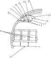
图1 在机身的横剖面内示意示出一高架行李存放箱在飞机中的设置情况;Fig. 1 schematically shows the arrangement of an overhead luggage storage box in an aircraft in a cross-section of the fuselage;
图2 蜂窝状加强的复合材料的高架行李存放箱的制造方法实例的透视图;Figure 2 is a perspective view of an example of a method of manufacturing an overhead luggage storage box of honeycomb-reinforced composite material;
图3 按照本发明实施的高架行李存放箱的侧视图;Figure 3 is a side view of an overhead luggage storage box implemented in accordance with the present invention;
图4a 图3中高架行李存放箱的细部IV的侧视图;Figure 4a is a side view of detail IV of the overhead luggage storage box in Figure 3;
图4b 图4a中细节的侧视图;Figure 4b is a side view of the detail in Figure 4a;
图5 本发明的高架行李存放箱的一个方案的透视图,包括成一件构成的加强结构和连接元件;以及Figure 5 is a perspective view of one version of the overhead luggage storage case of the present invention, including the reinforcing structure and connecting elements formed in one piece; and
图6可转动支承的高架行李存放箱的实施形式。Fig. 6 is an embodiment of a rotatably supported overhead luggage storage box.
具体实施方式 Detailed ways
图1在机身2的一部分的横剖面内示出一高架行李存放箱1在飞机中的设置。座位4通常固定在客机的内室的底板3上并在座位4的上方设置高架行李存放箱1。存放箱1通常经由悬挂装置5与飞机的一个承载结构,例如与机身2相连接。所谓承载结构也包括直接连接到固定的结构例如机身2上的全部元件。此外,可以通过一个托架6实现高架行李存放箱1与机身2之间的另一连接。FIG. 1 shows the arrangement of an overhead
高架行李存放箱1通常包括一固定的存放箱部件8,其包括一底板7、一后壁、上面和至少前面的一部分。固定的存放箱部件8具有一开口9,其可由一翻盖10关闭。在固定的存放箱部件8的底板7上设有加强结构11,后者可由金属支架构成,它例如通过粘合或螺钉连接与底板7相连接。在该加强结构11上设置各种在旅客头顶上方的照明装置、通风装置和供氧装置。固定的存放箱8在侧面具有侧壁12。位于高架行李存放箱1中的行李物件在底板7上施加力,其通常经由侧壁12被转入悬挂装置5中。在超过许用的载荷极限时撕下悬挂装置5或侧壁12,并且高架行李存放箱1或其中的行李物件可能落到旅客的头上。因此,按照本发明的高架行李存放箱1设有在加强结构11与悬挂装置5之间的连接元件17,借此减轻侧壁12的负担并避免存放箱1的损坏。The overhead
本发明并不限于图1中所示的固定的高架行李存放箱1,而也适用于最近较常用的可向下转动的或可移动的高架行李存放箱。The present invention is not limited to the fixed overhead
图2示出高架行李存放箱1由一构成固定的存放箱部件8的弯边围绕的凹槽的制造可能性,后者可由玻璃纤维或碳纤维的复合材料以多层结构制成。在两纤维增强的塑料覆盖层13、14之间设有蜂窝状填充料15。在固定的存放箱部件8的转折处没有蜂窝状填充料15并且覆盖层13和14彼此靠紧设置。因此可以将存放箱部件8放在一相应成形的模具上。同样将存放箱1的侧壁12放在该模具上并且例如与存放箱部件8粘合。该制造可以在一热压锅中在热和压力下完成。这样的制造过程的耗费是特别大的,因为对侧壁12和侧壁12与存放箱部件8之间的连接提出高的要求。FIG. 2 shows the production possibility of the overhead
图3示出本发明的高架行李存放箱1的侧视图。存放箱1包括一固定的存放箱部件8,其包括底板7。行李可经一开口9装入存放箱部件8中,该开口9优选构成是可关闭的。在存放箱部件8的上面设有一悬挂装置5。借助存箱部件8的底板7,设置一些优选由金属构成的挤压型材导轨形式的加强结构11。加强结构11与底板7相连接,例如粘合或螺钉连接。此外在加强结构11与悬挂装置5之间在高架行李存放箱1的侧面设有至少一个刚性的连接元件17。连接元件17具有各开口18,用以与加强结构11和悬挂装置5形锁合连接。将连接元件17构成为使其确保力流从在存放箱1的底板7上的加强结构11传向悬挂装置5。为了减轻重量可以在连接元件17中设置钻孔19或空隙20。这些钻孔19、空隙20等设置在出现的力为最小的这些部件。连接元件17由金属、塑料,特别是纤维增强的塑料制成。为了避免在极端情况下,例如飞机紧急着陆时高架行李存放箱1的不受控的反应,连接元件17可以包括预定的断裂点24,例如以变窄的形式(虚线所示)。与预定的断裂点24的末端可以连接用于消除运动能的装置,例如一设置成环线的安全带或一弹性元件(未示出)。Figure 3 shows a side view of the overhead
图4a和4b详细示出在连接元件17与加强结构11之间的连接的实例。为此在连接元件17中设有各开口18,加强结构11或其部分可插入该开口中。加强结构11凸出连接元件17的端部可以例如辅助用螺钉等固定,从而加强结构11相对于连接元件17的滑动是不可能的。此外,在存放箱1的侧壁12与连接元件17之间可以设置用以连接的粘合层21。4a and 4b show in detail an example of the connection between the
最后,图5示出本发明的一个方案,其中加强结构11和连接元件17成一件制成。加强结构11和连接元件17构成一摆动似的结构,其中设置高架行李存放箱1(示意示出的)。高架行李存放箱1的悬挂装置5通过相应的开口18穿过连接元件17并与飞机的承载结构相连接。Finally, FIG. 5 shows a variant of the invention in which the reinforcing
图6示出高架行李存放箱1的一个方案,其是可转动的,从而特别是在很大的飞机中便于存放行李物件。存放箱1包括一由一凹槽22构成的可动部件,其包括加强结构11。加强结构11按照本发明与连接元件17相连接,后者相对于存放箱1的纵向延伸基本上垂直设置。经由可与悬挂装置5(未示出)相连接的铰链23,凹槽与固定的存放箱部件(未示出)可转动地相连接。在可转动设置的高架行李存放箱1的实施形式中,不仅固定的存放箱部件8而且由一凹槽22构成的可动的存放箱部件均配备有按照本发明的连接元件17。FIG. 6 shows a variant of an overhead
当前的高架行李存放箱1,特别用于飞机,经受住较高的载荷,而没有提高高架行李存放箱1的制造费用。Current overhead
Claims (21)
Applications Claiming Priority (2)
| Application Number | Priority Date | Filing Date | Title |
|---|---|---|---|
| AT0159001A AT410657B (en) | 2001-10-09 | 2001-10-09 | OVERHEAD LUGGAGE RACK, ESPECIALLY FOR AIRPLANES |
| ATA1590/2001 | 2001-10-09 |
Publications (2)
| Publication Number | Publication Date |
|---|---|
| CN1802286A CN1802286A (en) | 2006-07-12 |
| CN100404373C true CN100404373C (en) | 2008-07-23 |
Family
ID=3688386
Family Applications (1)
| Application Number | Title | Priority Date | Filing Date |
|---|---|---|---|
| CNB028229320A Expired - Fee Related CN100404373C (en) | 2001-10-09 | 2002-09-16 | Overhead luggage storage compartment for an aircraft |
Country Status (8)
| Country | Link |
|---|---|
| US (1) | US7097138B2 (en) |
| EP (1) | EP1434713B1 (en) |
| CN (1) | CN100404373C (en) |
| AT (1) | AT410657B (en) |
| CA (1) | CA2460590C (en) |
| DE (1) | DE50202442D1 (en) |
| ES (1) | ES2238603T3 (en) |
| WO (1) | WO2003031260A1 (en) |
Families Citing this family (25)
| Publication number | Priority date | Publication date | Assignee | Title |
|---|---|---|---|---|
| AT413277B (en) * | 2003-12-01 | 2006-01-15 | Fischer Adv Components Gmbh | DEVICE FOR INTRODUCING AND DISTRIBUTING FORCES IN A LUGGAGE TRAY |
| EP1630098B1 (en) * | 2004-08-31 | 2009-04-01 | Airbus Deutschland GmbH | Attachment for aircraft interior parts |
| US8047468B2 (en) * | 2005-10-14 | 2011-11-01 | The Boeing Company | Stowage bin with shear fittings |
| US20070084966A1 (en) * | 2005-10-14 | 2007-04-19 | Haynes Michael S | Stowage bin with shear fittings |
| US7665692B2 (en) * | 2005-10-28 | 2010-02-23 | Airbus | Baggage bin door and baggage bin |
| CA2658623C (en) * | 2006-07-24 | 2015-02-03 | Airbus | Baggage bin and associated door intended in particular for an aircraft |
| DE102010026805B4 (en) * | 2010-07-10 | 2016-08-11 | Diehl Aerospace Gmbh | Device for supplying consumers in the overhead area of a passenger cabin, in particular in commercial aircraft |
| US8727278B2 (en) * | 2010-07-16 | 2014-05-20 | The Boeing Company | Article retention device |
| DE102011108895A1 (en) * | 2011-07-29 | 2013-01-31 | Airbus Operations Gmbh | Carrying structure for movable storage compartment |
| US9162617B2 (en) * | 2012-02-14 | 2015-10-20 | C&D Zodiac, Inc. | Pivot bin assembly |
| USD699662S1 (en) * | 2012-03-21 | 2014-02-18 | Mitsubishi Aircraft Corporation | Joint for aircraft luggage compartments |
| AT513939A1 (en) * | 2013-02-01 | 2014-08-15 | Facc Ag | Overhead overhead storage compartment for aircraft and aircraft with such overhead storage compartments |
| RU2615898C2 (en) * | 2013-02-12 | 2017-04-11 | Си Энд Ди ЗОДИАК, ИНК. | Swivel block of baggage compartment |
| US9327834B2 (en) * | 2013-10-04 | 2016-05-03 | Embraer S.A. | Overhead bin system |
| AT516642A1 (en) | 2014-12-15 | 2016-07-15 | Facc Ag | Electrically actuated movable overhead luggage compartment for aircraft |
| EP3436352B1 (en) * | 2016-04-01 | 2021-03-31 | B/E Aerospace, Inc. | Hinge for enlarging the volume of an aircraft storage bin |
| EP3251819B1 (en) | 2016-06-03 | 2021-09-29 | Airbus Operations GmbH | A method for manufacturing an overhead storage compartment for an aircraft cabin |
| US11566460B2 (en) | 2016-12-20 | 2023-01-31 | Mhi Rj Aviation Ulc | Hinge assembly |
| WO2019018300A1 (en) | 2017-07-17 | 2019-01-24 | Harper Engineering Company | Integrated stowage bin assembly |
| DE102017117274A1 (en) * | 2017-07-31 | 2019-01-31 | Airbus Operations Gmbh | Luggage compartment for hull or ceiling installation in a vehicle and method for making such a luggage compartment |
| CN109159739A (en) * | 2018-09-28 | 2019-01-08 | 厦门金龙旅行车有限公司 | It is a kind of to facilitate the passenger stock for picking and placing luggage |
| EP3702281B1 (en) * | 2019-03-01 | 2022-05-04 | Airbus Operations GmbH | Method and system for determining mechanical robustness of an overhead stowage bin for an aircraft and device for imparting mechanical load to an overhead stowage bin for an aircraft |
| EP4378837B1 (en) * | 2022-11-30 | 2025-06-11 | Airbus Operations GmbH | Installation system and method for installing a self-supporting framework structure |
| EP4438476B1 (en) * | 2023-03-29 | 2026-03-11 | Airbus Operations GmbH | Lightweight overhead stowage compartment and method of installing the same |
| CN119659949B (en) * | 2024-12-19 | 2025-09-30 | 中国航空工业集团公司西安飞机设计研究所 | Aircraft suitcase slide rail mounting structure |
Citations (6)
| Publication number | Priority date | Publication date | Assignee | Title |
|---|---|---|---|---|
| US4275942A (en) * | 1978-12-26 | 1981-06-30 | The Boeing Company | Stowage bin mechanism |
| US5549258A (en) * | 1994-12-23 | 1996-08-27 | Heath Tecna Aerospace Company | Retrofit luggage bin assembly compatible with existing aircraft bin supports |
| US5785788A (en) * | 1992-02-20 | 1998-07-28 | Fischer Advanced Composite Components Gmbh | Process for manufacturing a stowage container for use in an aircraft |
| US5817409A (en) * | 1993-12-17 | 1998-10-06 | Fischer Advanced Composite Components Gesellschaft M.B.H. | Fabric prepreg produced from such fabric, lightweight component from such prepregs, overhead baggage rack for aircraft |
| US5842668A (en) * | 1997-02-27 | 1998-12-01 | Hexcel Corporation | Quick fit overhead stowage compartment |
| US6007024A (en) * | 1995-10-04 | 1999-12-28 | Fischer Advanced Compositecomponents Gesellscgaft M.B.H. | Safety device for a container disposed in the interior of an aircraft |
Family Cites Families (23)
| Publication number | Priority date | Publication date | Assignee | Title |
|---|---|---|---|---|
| US5108048A (en) * | 1989-09-15 | 1992-04-28 | The Boeing Company | Stowage bin and support panel system for convertible aircraft and method of installation |
| AT397906B (en) * | 1992-02-20 | 1994-08-25 | Fischer Adv Components Gmbh | PLASTIC CONTAINER |
| US5785202A (en) * | 1992-02-20 | 1998-07-28 | Fischer Advanced Composite Components Gmbh | Stowage container for the use in aircraft |
| DE9214592U1 (en) * | 1992-10-28 | 1993-02-11 | Deutsche Aerospace Airbus GmbH, 2000 Hamburg | Overhead luggage rack with lowerable tray, particularly for use in passenger aircraft |
| US5395074A (en) * | 1993-03-10 | 1995-03-07 | Health Tecna Aerospace Company A Unit Of Ciba-Geigy | Retrofit bezel assembly |
| US6062509A (en) * | 1994-12-23 | 2000-05-16 | Hexcel Corporation | Retrofit centerline luggage bin assemblies compatible with existing aircraft bin supports |
| DE19540929C2 (en) * | 1995-11-03 | 1997-08-14 | Daimler Benz Aerospace Airbus | Luggage rack in a passenger cabin, especially in a commercial aircraft |
| DE19546302C2 (en) * | 1995-12-12 | 1998-08-20 | Daimler Benz Aerospace Airbus | Luggage rack |
| DE19633469C1 (en) * | 1996-08-20 | 1997-09-04 | Daimler Benz Aerospace Airbus | Device for holding overhead baggage compartments in aircraft passenger cabins |
| AT404926B (en) * | 1997-07-07 | 1999-03-25 | Fischer Adv Components Gmbh | DEVICE FOR DETACHABLE FIXING OF COVER PLATES OD. DGL. |
| US5934615A (en) * | 1997-08-25 | 1999-08-10 | Hexcel Corporation | Luggage bins with articulating mechanism |
| GB9721360D0 (en) * | 1997-10-08 | 1997-12-10 | Transmatic Europ Limited | Rack unit |
| US5988565A (en) * | 1998-02-25 | 1999-11-23 | Kingdom Builders R & D, L.L.C. | Overhead aircraft luggage bin with safety mechanism |
| US6045204A (en) * | 1998-10-13 | 2000-04-04 | Hexcel Corporation | Overhead stowage bins in aircraft |
| US6398163B1 (en) * | 1999-06-10 | 2002-06-04 | Jerry Welch | Enhanced luggage bin system |
| DE10001038B4 (en) * | 2000-01-13 | 2004-01-29 | Airbus Deutschland Gmbh | Luggage rack with a lowerable luggage compartment, especially for an aircraft passenger cabin |
| DE20016405U1 (en) * | 2000-09-20 | 2002-02-14 | HYMER-LEICHTMETALLBAU GMBH & CO. KG, 88239 Wangen | Luggage compartment of a vehicle |
| DE10063932C2 (en) * | 2000-12-20 | 2002-11-28 | Airbus Gmbh | Luggage rack with a lowerable luggage compartment, especially for an aircraft passenger cabin |
| US6527325B2 (en) * | 2001-01-30 | 2003-03-04 | Britax Health Tecna Inc. | Pull-down stowage bin restraint |
| NL1017811C2 (en) * | 2001-04-10 | 2002-10-11 | Stork Prod Eng | Cabin baggage assembly with underpressure. |
| US6814331B2 (en) * | 2002-05-10 | 2004-11-09 | Goodrich Hella Aerospace Lighting Systems Gmbh | Device for removably fastening a first part to a second part mountable in an aircraft |
| US6899299B2 (en) * | 2002-07-26 | 2005-05-31 | The Boeing Company | Luggage bins and aircraft passenger cabin ceilings |
| US6883753B1 (en) * | 2004-03-25 | 2005-04-26 | The Boeing Company | Overhead bin and monument attachment support system |
-
2001
- 2001-10-09 AT AT0159001A patent/AT410657B/en not_active IP Right Cessation
-
2002
- 2002-09-16 DE DE50202442T patent/DE50202442D1/en not_active Expired - Lifetime
- 2002-09-16 CA CA2460590A patent/CA2460590C/en not_active Expired - Fee Related
- 2002-09-16 EP EP02774140A patent/EP1434713B1/en not_active Expired - Lifetime
- 2002-09-16 ES ES02774140T patent/ES2238603T3/en not_active Expired - Lifetime
- 2002-09-16 US US10/489,951 patent/US7097138B2/en not_active Expired - Lifetime
- 2002-09-16 WO PCT/AT2002/000267 patent/WO2003031260A1/en not_active Ceased
- 2002-09-16 CN CNB028229320A patent/CN100404373C/en not_active Expired - Fee Related
Patent Citations (6)
| Publication number | Priority date | Publication date | Assignee | Title |
|---|---|---|---|---|
| US4275942A (en) * | 1978-12-26 | 1981-06-30 | The Boeing Company | Stowage bin mechanism |
| US5785788A (en) * | 1992-02-20 | 1998-07-28 | Fischer Advanced Composite Components Gmbh | Process for manufacturing a stowage container for use in an aircraft |
| US5817409A (en) * | 1993-12-17 | 1998-10-06 | Fischer Advanced Composite Components Gesellschaft M.B.H. | Fabric prepreg produced from such fabric, lightweight component from such prepregs, overhead baggage rack for aircraft |
| US5549258A (en) * | 1994-12-23 | 1996-08-27 | Heath Tecna Aerospace Company | Retrofit luggage bin assembly compatible with existing aircraft bin supports |
| US6007024A (en) * | 1995-10-04 | 1999-12-28 | Fischer Advanced Compositecomponents Gesellscgaft M.B.H. | Safety device for a container disposed in the interior of an aircraft |
| US5842668A (en) * | 1997-02-27 | 1998-12-01 | Hexcel Corporation | Quick fit overhead stowage compartment |
Also Published As
| Publication number | Publication date |
|---|---|
| US7097138B2 (en) | 2006-08-29 |
| EP1434713A1 (en) | 2004-07-07 |
| CN1802286A (en) | 2006-07-12 |
| CA2460590A1 (en) | 2003-04-17 |
| EP1434713B1 (en) | 2005-03-09 |
| DE50202442D1 (en) | 2005-04-14 |
| WO2003031260A1 (en) | 2003-04-17 |
| US20050040287A1 (en) | 2005-02-24 |
| CA2460590C (en) | 2011-05-31 |
| AT410657B (en) | 2003-06-25 |
| ATA15902001A (en) | 2002-11-15 |
| ES2238603T3 (en) | 2005-09-01 |
Similar Documents
| Publication | Publication Date | Title |
|---|---|---|
| CN100404373C (en) | Overhead luggage storage compartment for an aircraft | |
| CN104955730B (en) | Overhead Stowage Compartment for aircraft | |
| CA2186981C (en) | Safety device for a container disposed in the interior of an aircraft | |
| CN101511674B (en) | Aircraft doorway | |
| US7832685B2 (en) | Stowage bin with shear fittings | |
| EP0751064B1 (en) | Extensions for storage bins | |
| US8453972B2 (en) | Device for connecting movable parts with structural elements of airplanes or the like | |
| CN101321664B (en) | Aircraft pressurized cabin doors made of fiber composites | |
| CN106715266B (en) | Overhead luggage compartment for aircraft | |
| US8047468B2 (en) | Stowage bin with shear fittings | |
| US8087612B2 (en) | Aircraft seat supporting structure | |
| US10661880B2 (en) | Cable-free and strut-free fairing for supporting a person | |
| EP2800715B1 (en) | Air cargo container | |
| CN102202965B (en) | Fitting for trimming the horizontal stabiliser of an aircraft | |
| CN101663199B (en) | Bearing application for fastening step flights in an aircraft | |
| US5785202A (en) | Stowage container for the use in aircraft | |
| US11623733B2 (en) | Bead-stiffened movable surfaces | |
| HK1178498B (en) | Use of a lightweight construction element | |
| HK1178498A1 (en) | Use of a lightweight construction element |
Legal Events
| Date | Code | Title | Description |
|---|---|---|---|
| C06 | Publication | ||
| PB01 | Publication | ||
| C10 | Entry into substantive examination | ||
| SE01 | Entry into force of request for substantive examination | ||
| C14 | Grant of patent or utility model | ||
| GR01 | Patent grant | ||
| C56 | Change in the name or address of the patentee |
Owner name: FACC STOCK CO., LTD. Free format text: FORMER NAME: FISCHER ADVANCED COMPOSITE COMPONENTS STOCK CO., LTD. |
|
| CP03 | Change of name, title or address |
Address after: Austria governor Reed Yin Patentee after: FACC AG Address before: Austria Chris Patentee before: Fischer Adv Components GmbH |
|
| CF01 | Termination of patent right due to non-payment of annual fee | ||
| CF01 | Termination of patent right due to non-payment of annual fee |
Granted publication date: 20080723 Termination date: 20200916 |