CN100397532C - Flexible high-impedance interconnect cable having unshielded wires - Google Patents
Flexible high-impedance interconnect cable having unshielded wires Download PDFInfo
- Publication number
- CN100397532C CN100397532C CNB038249170A CN03824917A CN100397532C CN 100397532 C CN100397532 C CN 100397532C CN B038249170 A CNB038249170 A CN B038249170A CN 03824917 A CN03824917 A CN 03824917A CN 100397532 C CN100397532 C CN 100397532C
- Authority
- CN
- China
- Prior art keywords
- lead
- cable
- cable assembly
- leads
- conduit
- Prior art date
- Legal status (The legal status is an assumption and is not a legal conclusion. Google has not performed a legal analysis and makes no representation as to the accuracy of the status listed.)
- Expired - Lifetime
Links
Images


Classifications
-
- H—ELECTRICITY
- H01—ELECTRIC ELEMENTS
- H01B—CABLES; CONDUCTORS; INSULATORS; SELECTION OF MATERIALS FOR THEIR CONDUCTIVE, INSULATING OR DIELECTRIC PROPERTIES
- H01B7/00—Insulated conductors or cables characterised by their form
- H01B7/04—Flexible cables, conductors, or cords, e.g. trailing cables
- H01B7/041—Flexible cables, conductors, or cords, e.g. trailing cables attached to mobile objects, e.g. portable tools, elevators, mining equipment, hoisting cables
-
- H—ELECTRICITY
- H01—ELECTRIC ELEMENTS
- H01B—CABLES; CONDUCTORS; INSULATORS; SELECTION OF MATERIALS FOR THEIR CONDUCTIVE, INSULATING OR DIELECTRIC PROPERTIES
- H01B11/00—Communication cables or conductors
- H01B11/18—Coaxial cables; Analogous cables having more than one inner conductor within a common outer conductor
- H01B11/1895—Particular features or applications
-
- H—ELECTRICITY
- H01—ELECTRIC ELEMENTS
- H01B—CABLES; CONDUCTORS; INSULATORS; SELECTION OF MATERIALS FOR THEIR CONDUCTIVE, INSULATING OR DIELECTRIC PROPERTIES
- H01B11/00—Communication cables or conductors
- H01B11/18—Coaxial cables; Analogous cables having more than one inner conductor within a common outer conductor
- H01B11/20—Cables having a multiplicity of coaxial lines
-
- H—ELECTRICITY
- H01—ELECTRIC ELEMENTS
- H01B—CABLES; CONDUCTORS; INSULATORS; SELECTION OF MATERIALS FOR THEIR CONDUCTIVE, INSULATING OR DIELECTRIC PROPERTIES
- H01B7/00—Insulated conductors or cables characterised by their form
- H01B7/04—Flexible cables, conductors, or cords, e.g. trailing cables
- H01B7/048—Flexible cables, conductors, or cords, e.g. trailing cables for implantation into a human or animal body, e.g. pacemaker leads
-
- H—ELECTRICITY
- H01—ELECTRIC ELEMENTS
- H01B—CABLES; CONDUCTORS; INSULATORS; SELECTION OF MATERIALS FOR THEIR CONDUCTIVE, INSULATING OR DIELECTRIC PROPERTIES
- H01B7/00—Insulated conductors or cables characterised by their form
- H01B7/08—Flat or ribbon cables
- H01B7/0892—Flat or ribbon cables incorporated in a cable of non-flat configuration
Abstract
A cable assembly has a number of wires, each with opposed first and second ends. The wires have intermediate portions between the first and second ends, and the intermediate portions are detached from each other. A conductive shield loosely encompasses all the wires, and the shield and wires are received within a resilient catheter sheath. A medical imaging transducer may be connected to one end of the wires, and the wires may be ribbonized at the other end. The transducer may be an ultrasound or other imaging transducer, and may be received in the catheter.
Description
The cross reference of related application
The application be on November 7th, 2002 United States Patent (USP) trademark office submit to the 10/290th, the part continuation application of No. 590 U.S. Patent applications, and patent application 10/290,590 is again that December 18 calendar year 2001 is in the 10/025th of United States Patent (USP) trademark office submission, the part continuation application of No. 096 U.S. Patent application, the content of these applications all is contained in this.
Technical field
The present invention relates to multiconductor cable, more particularly, the present invention relates to medical procedure in the small dimension lead that uses of conduits join.
Background technology
The application scenario of some demand requires miniaturization multiconductor cable assembly.For fear of the unnecessary heavy cable that occurs when needing many conductors, and adopt very thin conductor.In order to limit electrical noise and interference, the concentric conductor with screen is generally used for those conductors.Insulating sleeve centers on center conductor, and it and the screen conduction of conduction are isolated.A branch of such lead is centered on by braid shielded thing that conducts electricity and outer protection cover institute.
Need some application of many different conductors to wish cable very flexible, soft or " soft ".In the application of the cable that for example is connected to the medical ultrasonic transducer, even the rigid cable with crooked medium resistance also makes the ultrasonic imaging difficulty.Yet in the conventional method of protection cable, this wire harness may have undesirable rigidity.In addition, what people required is, cable has relatively than light weight, and gas is not held in place sonac so that it does not need to go to great pains, to be used for imaging.At present, ultrasonic technique personnel a part of cable loop on their wrist, with at the situation lower support cable that does not drag on transducer.
The lead of fine gauge is met by utilizing very to the demand of flexible and lightweight cable.Although it is effective to make the technology of thin specification concentric conductor, be again simultaneously strict and expensive.Be total diameter of wire of needing realizing, the shielding conductor that center conductor and spiral twine must be very thin, near the limit of practical manufacturability.The cable that is used for some application scenarios in the past adopts unscreened conductor, but is well known that, these are unsuitable in the application scenario of for example medical ultrasound imaging, in these occasions, needs high impedance, low electric capacity and very limited interference.
In addition, the cable assembly with a large amount of leads is lost time when assembling with miscellaneous part and costliness.When independent lead during with a branch of use, which wire end people are not easy to discern corresponding to the lead of selecting at this bundle conductor other end, thereby need heavy long run test.Usually, be connected in the conductor wire end of cable one end on the parts of connector for example or printed circuit board (PCB), and this connector or plate are connected on the testing equipment, this equipment provides voltage for every lead, one time one, thereby the assembler can be connected the conductor wire end of identification with suitable connector on second connector or plate.
Wherein the flat cable of lead with cable one end and other end maintenance order may propose this special problem.Yet in all seam ribbon conductor together, these lead opposings are crooked, formed the rigid cable of not expecting.Moreover, be not easy to form compact cross section and increase volume undesirably along the folding ribbon of a plurality of longitudinal fold circuits, and can not be provided at the circular cross section that needs in many application.
In other application, small size and high-performance are crucial.For medical imaging, particularly adopt the ultrasonic imaging of internal sensor, for example be used for the three-dimensional imaging of patient's heart function, it is very important producing and launch useful image to external instrument for transducer internally at a plurality of circuit High Data Rates.In addition, the diameter of this bundle conductor is vital for being embedded in patient's vein or artery to arrive image space (for example heart).In the selectivity of for example intestines and stomach imaging is used, the restriction cable size for the patient comfortable and for other elements such as for example light conduits and operation imports or the mechanical organ of surgical technique and tools to abdicate the space be important.Yet current cable is bigger than the application scenario of the imaging catheter that is suitable for for example advancing, and lacks enough performances.For running through esophagus (transesophageal) probe, owing to allow less intrusion or comfortable operation more, reduced size is very important.Moreover the cable of appropriate size lacks to be convenient in patient's body by the mechanical performance with the arrival precalculated position.
Summary of the invention
The present invention overcomes restriction of the prior art by a kind of cable assembly is provided.This cable assembly has many leads, and wherein each lead has the first and second relative ends.This lead has mid portion between this first and second end, and this mid portion is separated from each other.The conductive shields loosely is around all leads, and this screen and lead are contained in the catheter sheath of firm resilient spring like.The medical imaging transducer can be connected to lead one end, and this lead can be in other end band shapeization.This transducer can be ultrasonic or other imaging sensor, and can hold in this conduit, perhaps as the terminal part of this conduit.
Description of drawings
The purpose and the feature that are considered to the present disclosure of novelty are specifically set forth in the accessory claim book.By with reference in conjunction with the accompanying drawings following description, can get the best understanding the following statement of these purposes and advantage with other purposes and advantage at the present disclosure of structure and mode of operation.
Fig. 1 is the perspective view of the cable assembly of most preferred embodiment according to the present invention.
Fig. 2 is the perspective view according to the wire guiding member of embodiment among Fig. 1.
Fig. 3 is the amplification view according to the wire guiding member terminal part of embodiment among Fig. 1.
Fig. 4 is the amplification view according to the cable assembly of embodiment among Fig. 1.
Fig. 5 is the amplification view of cable assembly under case of bending according to embodiment among Fig. 1.
Fig. 6 is for selecting the amplification view of the cable assembly parts of embodiment according to the present invention.
Fig. 7 is for selecting the amplification view of the cable assembly parts of embodiment according to Fig. 6.
Fig. 8 is for selecting the partial cut view of the cable assembly parts of embodiment according to the present invention.
Fig. 9 is for selecting the amplification view of the cable assembly parts of embodiment in addition according to the present invention.
Figure 10 is for selecting the amplification view of the cable assembly of embodiment according to Fig. 9.
Figure 11 is for selecting the perspective view of the cable assembly parts of embodiment in addition according to the present invention.
Figure 12 is for selecting the amplification view of the cable assembly of embodiment according to Figure 11.
Embodiment
Fig. 1 show have connector end 12, transducer tip 14 and the cable assembly 10 that is connected flexible cable 16.This connector end and the transducer tip that illustrate are the example that can be connected to the parts of cable 16.In this example, this connector end comprises the circuit board 20 with connector 22, and wherein this connector 22 is used to be connected to for example electronic instrument of ultrasonic imaging machine.This connector end comprises connector shell 24 and centers on the releasing tensioning mouth (strainrelief) 26 of this cable end piece.In opposing ends, sonac 30 is connected on this cable.
This cable 16 comprises numerous trickle coaxial shielding lines 32.As shown in same among Fig. 2, conductor arrangement in groups 33, wherein every group has the band-like portions 34 of band shapeization and the ravel 36 of extension at each end, and wherein this ravel 36 is extending between these band-like portions and on the almost whole length of this cable.Each band-like portions comprises one deck lead adhering to each other that is arranged side by side, and this lead is trimmed to screen and the center conductor that exposes every lead.At this ravel, lead is separated from one another except that it is terminal.
According to the needs of cable use occasion, the screen of every lead and conductor dbus are crossed any conventional method and are connected to circuit board, perhaps are connected to any electronic component or connector.The ravel 36 of this lead extends in the whole length of removing the cable between the tensioning mouth, passes this releasing tensioning mouth, and enters in band-like portions layout and the housing that is connected.
Each all indicates unique mark this band-like portions 34, so that the assembler connects given group relative band-like portions, and particular lead end in organizing at each is connected.Group identifier 40 is stamped on these band-like portions, and the first lead identifier 42 in each band-like portions guarantees that first lead is each terminal can identification in each band-like portions order simultaneously.Importantly, in the lead order of each band-like portions, every group has man-to-man corresponding relation.Therefore, the assembler can discern the n lead from the sign first terminal lead of given group " A ", and it is corresponding with n lead in relative band-like portions that this identifies the first terminal lead, and do not need to seek correct lead with the trial and error pricing long run test.Mid portion 36 allows toward each other or moves with mid portion with respect to other groups in this cable even this of every group scatters, and this corresponding relation also can be guaranteed.
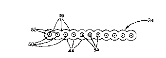
Fig. 3 shows the cross section of typical end, and wherein at the external sheath layer 44 of the portion of being welded to connect 46, lead connects, and the conductive shields 50 of each lead keeps electricity to isolate with other leads simultaneously.And internal insulator 52 and center conductor 54 remain intact and isolate.In selecting embodiment, by utilize adhesive between the adjacency restrictive coating 44, by each restrictive coating being adhered on public bar or the sheet or, can fixing these band-like portions by mechanical clamp.
Fig. 4 shows the cable cross-section that runs through the most of length of this cable, wherein removes these band-like portions, and this mid portion is shown.This lead is loosely received in soft cylindric cable cover(ing) 60 inside.Equally as shown in Figure 1, conductive braided fabric sheath 62 centers on whole leads, and resides in this jacket inner surface to limit duct 64.Get back to Fig. 4, this channel diameter is chosen to desired bigger a little than tightly holding whole leads.As shown in Figure 5, form the configuration of a handle owing to described lead can freely slide, this just provides and has made cable can become curved ability under the situation in minimum resistance when suffering from a sharp turn.In the configuration that this is evened up, the cross section in duct reduces when being maintained at straight line than cable, as shown in Figure 4.
In most preferred embodiment, there are 8 groups, every group has 16 leads, but any one all can change in fact in these numerals, and some embodiment can one group use lead.This lead preferably has 0.016 inch external diameter, but depends on the application scenario, and these and other size variable becomes virtually any size.This sheath has 0.330 inch external diameter and 0.270 inch aperture.This has just formed 0.057 inch duct cross section (when straight under circular situation).When the lead trend of scattering only is assembled into than the big slightly cross-sectional area of their areas, then in the duct, has enough big space under normal conditions.This allows lead each other around Flexible Sliding, and makes mantle friction minimum between lead and the lead, if for example by the conventional practice of conductor shielding thing around the bundle conductor coating, lead wraps in together tightly, then this friction may occur.In most preferred embodiment, if for example this cable is folded between two fingers and allows to bend to the nature radius, then the bending radius of 0.75 inch or 2 times cable size has minimum bending force, in fact, the softness of bending radius and shortage bending resistance is by limiting nothing but the total resistance to bending of each parts.Because every lead is very thin, and has the minimum resistance bending force on the radius of cable size scale, thus lead resistance and seldom being increased on the resistance to bending of sheath and screen, so form total resistance to bending.
Unscreened embodiment
Fig. 6 shows the cross section according to the typical end 34 ' of the lead group 33 ' of alternate embodiment of the present invention.This selection embodiment is different with most preferred embodiment to be, the lead 32 ' of forming cable is unscreened toward each other, and every lead has the center conductor 54 ' that includes only the lead current-carrying part.The only current-carrying part of every lead is a center conductor, and is center conductor and screen at unique conductor of this cable.This center conductor 54 ' is only centered on by single insulating barrier or insulating sleeve 44 '.This individual layer is made by a kind of material, and the manufacturing of simplifying is provided.
As in this most preferred embodiment, this lead is connected to each other in the portion of being welded to connect 46 ' at their sheath 44 '.In selecting embodiment, if by utilize between the adjacency restrictive coating 44 ' adhesive, by each restrictive coating is adhered on the public bar or sheet, by mechanical clamp or any way, can fix these band-like portions, so that the end of band shapeization to be provided, wherein this end comprises the personalized design of flat cable mid portion.
Fig. 7 shows the selection embodiment cable 16 ' of the cable group 33 ' that adopts Fig. 6.This part is taken from any centre position on this cable, removes banded end.This lead 32 ' is loosely received in soft cylindric cable cover(ing) 60 ' inside.With most preferred embodiment is the same as shown in Figure 1, conductive braided fabric shielding thing 62 ' loosely centers on whole leads, and resides in this jacket inner surface to limit duct 64 '.Get back to Fig. 7, this channel diameter is chosen to desired bigger a little than tightly holding whole leads.As shown in Figure 5, this just provides the ability that bends to the sharp turn with minimal resistance for cable, and similarly, as shown in Figure 6, when lead kept straight, this lead optionally slides into evened up structure, and wherein this duct cross section reduces from circular cross section.
Utilize this unscreened lead, loose being considered to for the cable performance particular importance.This be since loose make lead relatively other lead along this mid portion curved in length, thereby given lead only comes and any other special lead or lead group adjacency with fraction length.If this screen or sheath coat around lead tightly during manufacture, then this lead layout respect to one another can not be a product at random, and will determine along with the pattern that forms at assembly process.
Like this, at first, the possible nonrandom pattern that loose assurance forms during fabrication can not keep during device lifetime.Nonrandom pattern like this can be, in closs packing honeycomb cross section mode, wherein do not allow lead along it length or move relative to each other in the future, this lead is being followed straight line path along whole length with other identical leads adjacency in fact.Secondly, loose permission lead moved along with the time, thereby this pattern can not be maintained fixed for the whole life period that installs.When using, as the storage loading and unloading during cable when crooked, this lead is considered on cable length each other around " creeping ", along with the time presents different mode and position randomly.The 3rd, the tendency that this lead is creeped makes them present different stochastic models on the whole length of cable, thereby this cable is estimated only to keep adjacent for the very short part of cable length with other given cables, has limited the influence that any other lead causes cross-talk therein.
It should be understood that along length in the layout of any position lead and the relevance that has minimum along cable length short distance lead pattern.Even for beeline along cable length, wherein lead can not move too much from its position, can think, have no reason to believe that lead tendency or trend remain on same position, two adjacent wires will can not leave at equidirectional, and this will cause them to keep adjacency each other at enough cable lengths.
Should also be understood that the lead trend is left given position so that (if allowing at random) lead passes the cable maximum gauge through several speed of round stroke completely.This is based on leaving the trend of specified rate at given length in side direction, even can not estimate to produce zig-zag path in practice from this screen one side to the opposite side crooked route.Because every lead and near other any leads have very small distance, thereby being produced the possibility of disturbing, other leads are distributed in extensively on other leads, wherein this influence minimizes, and allows for many application scenarios.For ultrasonic imaging, wherein this transducer has the intrinsic signal to noise ratio of about 35dB, compares with observe performance in the acoustics crosstalk, selects the performance of the preferred example of embodiment to mate well.
In selecting the preferred embodiment of embodiment, there are 7 groups, every group has 18 leads, but any one all can change in fact in these numerals, and some embodiment can one group use lead.This lead has can be single or become a strand lead, and be suitable for band shapeization and have the material isolation of requirement dielectric constant.For the cable that is used for typical ultrasonic imaging application scenario, general conductor will be 38 to the 42AWG high strength copper alloy.Preferably, insulation can be a low density polyolefin, also is feasible and use fluoropolymer.This dielectric constant is preferably in 1.2 to 3.5 scope.
The banded end of conductor length comes down to the outside of cable cover(ing) and screen.This end becomes band shape at interval with a determining deviation or center to center, this spacing or be homogeneous at interval, and be chosen to and the pad of the circuit board that will be fixed is complementary.In selecting the preferred example of embodiment, this conductor is sub-thread 40AWG copper (0.0026 " diameter), simultaneously insulator be the to have 0.006 overall conduction diameter of " the microcell polyolefin of wall thickness provides 0.015 "." the spacing of banded end that this is well suited for provides 0.014.Select insulating material to comprise that other solid, foam or other air strengthen low temperature compound and fluoropolymer.
This selection embodiment has the several performances different with most preferred embodiment.Shielded conductor forms every foot lower electric capacity by utilizing not.Compare with above-mentioned example, do not have with the not shielding of adopting the 40AWG conductor in the example that every foot 7pF compares in the coaxial selection scheme, the scheme of shielding has the electric capacity of about every foot 17pF.It is the 12pF/ foot that electric capacity is calculated in this expection that does not shield scheme, so this desirable reduction electric capacity is unpredictable consequence.What should believe is, adjacent lead is as the effect of every lead of shielding, thereby the effective spacing between conductor and screen not have the gap of basis and outer cable sheath fully, but according to the nominal range of adjacent wires conductor.When the signal carrying conductor that uses other signal carrying leads of conduct shielding will be estimated to form undesirable crosstalk, the random position of this lead was restricted to the level that the important application occasion allows fully to this influence with crooked.
Owing to do not need material and processing charges to be used for adopting the shielding and second dielectric layer, thereby this unscreened selection scheme generally has lower manufacturing cost.This unscreened selection scheme has lower weight than shielding scheme, and wherein every foot common weight of cable is 13.5 grams, and every foot cable is the 21-26 gram in the shielding scheme, reduces about 1/3 to 1/2.This uses cable more comfortable for the ultrasonic technique personnel, has reduced the tightening force on cable termination, and reduces user's fatigue.
Using not, the embodiment of shielded conductor has avoided another important design constraint.Usually, the electric capacity of concentric conductor depends on the gap between this center conductor and screen.For some particular application provides desirable low electric capacity (high impedance), the cable miniaturization that the diameter of every lead holds given number of conductors by this gap width, restriction restricts, and no matter how little this center conductor or shielding conductor be.(this is constrained to the condition of making around very trickle concentric conductor except that this actual manufacturing and costs constraints.Yet), do not need conductor shielding with the situation that prevents crosstalk under, every lead can have provide with adjacent wires and the insulation of cable shield thing minimum requirements than film dielectric layer.Even this electric capacity is by the interval constraint of conductor and adjacent wires conductor, two thickness that this also has benefited from wire insulation make its obvious miniaturization.
For the electric capacity of further minimizing is provided, but one or two edge conductors ground connection of each ribbon (need to utilize additional lead to offer the signal carrying lead of determined number.) it has been found that when an edge conductors during each terminal ground connection, near the lead of surface traverse, this electric capacity increases about 1.0pF for.On the curve that flattens away from ground, this electric capacity is higher for the lead away from ground, and is very fast near rising on the ground.In the situation of and more consistent electric capacity lower, allow additive wire, two edge ground connection of each ribbon at needs.This can compare electric capacity for providing on the most subaerial lead, wherein have only the rising slightly of about 0.2pF for the center conductor away from the edge.
Basically, as discussed above such, be contemplated that usually with coaxial connector and compare that unscreened conductor produces the crosstalk performance of unacceptable reduction, particularly the length that prolongs for lead, small dimension conductor and approaching at interval.Yet, allow lead to keep loose and pass most of cable length and avoided this worry total unexpectedly with normal flat cable.Because lead is not connected to each other, and since cable cover(ing) have enough loose, thereby this lead allows to move around, causing determining unlikely is that any two leads will keep close parallel each other, this will produce the crosstalk problem.The bending of cable has the effect of lead in tow during use, thereby on whole cable length, does not have lead can estimate to keep and identical other lead adjacency.Just as discussed above, utilize the banded structure of only controlling endways and arranging, sign can make annexation form reliably and effectively one to one.
As shown in Figure 8, the preferred or alternative embodiment of selection all can have the soft belt 100 that spiral twines.This band twines around near end this connector 12, and this winding only departs from this bundle conductor at lead and carries out with before extending to band-like portions 34.This tape wrap is as spacer, and to reduce wearing and tearing and the fatigue effect that repeats the cable bending, this is the problem of special concern in hand-held rope is tied device.Thereby this winding part has prolonged cable useful life.This winding spacer applies at the cable end piece that repeated flex takes place.Preferably, this spacer extends on about one foot length.Verified is that in long flex life was provided, twining certain zone with expansion PTFE (polytetrafluoroethylene) belt was effectively, while and this cable flexibility of not obvious degradation.The thickness that preferably, this belt has 0.5 " width, 0.002 ", 0.33 " winding spacing, and twine with 25 gram limited Tension, so that avoid having the fine and close bundle conductor that limits curvature.
Greatly-ground connection embodiment
Fig. 9 shows according to alternate embodiment of the present invention lead group 33 " typical end 34 " cross section.This selection embodiment is different with the foregoing description to be, except the signal carrying lead 32 ' of forming cable, has the other earthing conductor 110 of big specification conductor 112 and thin dielectric layer 114 in addition.Preferably, this external diameter of isolating earth lead 110 is approximately identical with the external diameter of this signal carrying lead.Therefore, as shown in figure 10, this end is the flat rubber belting of thickness, and earthing conductor tends to itself being distributed in randomly in this signal carrying lead 32 '.
As indicated like that preferably, this holding wire is 40AWG copper (0.0026 " diameter), and it is by 0.006 " insulator of wall thickness centers on, and the total external diameter of lead is 0.015 ".Not carrying of earth lead high-frequency signal is not so need particular insulator thickness yet; Only needing minimum insulator to carry out resistive with prevention with other conductors contacts.Therefore, earth lead is 32AWG copper (0.008 " diameter), has 0.0045 nominal insulation thickness, and external diameter is 0.017 ".
In selecting embodiment, earth lead can be than less in most preferred embodiment or bigger, but preferably, make earth lead significantly greater than holding wire, so that enough conductivities to be provided.Each ribbon adopts two earth leads to be considered to more consistent electric capacity is provided in these band-like portions at each ribbon edge, and reduces any edge effect, if signal conductor is positioned at the edge this effect may take place.
Yet there is no need has two earth leads just on each ribbon, and also unnecessary all earth leads that make all are positioned at this ribbon edge.In selecting embodiment, earth lead can be clipped in the middle of the holding wire.In needing the situation of higher capacitance, cable weight and diameter have not been strict with so, and earth lead quantity can equal or exceed holding wire quantity, for example by earth lead and holding wire are arranged alternately.This electric capacity can be adjusted for each application scenario, promptly carries out this adjustment by the earth lead that adopts selected quantity, and these earth leads are proved electric capacity (perhaps impedance) so that requirement to be provided in theory or with experimental technique.Number of conductors can also be expressed as the ratio of earth lead quantity and holding wire quantity.In other selection embodiment, this non-earth lead maskable is as traditional coaxial cable.
For more earth lead is provided, this earth lead can scatter along every n the position of ribbon, the earth lead (for example, ground wire, holding wire, holding wire, ground wire, holding wire, holding wire, ground wire, holding wire, holding wire, ground wire) that for example provides the group with a plurality of holding wires to replace.Selecting among the embodiment in addition, this earth lead needn't be included in the identical ribbon by the picture signals line like that, and can separated wires, perhaps is connected in they self the ribbon.In any case, at mid portion, this earth lead each other or loose with respect to holding wire so that they benefit from the above-mentioned randomization that discusses.
What can believe is, adopts holding wire and earth lead to limit the performance of cable in applications of ultrasound at the prior art of higher resistance conductor relatively.Specifically, have such high impedance as the high impedance of the conductor in signal ground loop, this high impedance causes causing on the conductor nearby " signal allocation person " effect of noise.The traditional coaxial shielding thing that is used for the applications of ultrasound occasion comprises more metals (this means low resistance and impedance).In addition, the adjacent signals line in coaxial shielding object space case is isolated (around those of each signal conductor) by two screens.
Earth lead provides lower impedance behavior by utilizing greatly, and does not have volume, expense and the weight of these conventional methods.Further guarantee along the combination with loose screen of mid portion length with the tendency that different conductor is got in touch at random: signal conductor only is subjected to the influence at the adjacent earth lead of cable length finite part comparably.
Although discuss at preferred and selection embodiment above, the present invention does not think such restriction.For example, replace at the fully independently loose each other lead of mid portion, but this lead packet layout, and other groups are scattered relatively.These groups can comprise parallel to (as the 2-conductor strip), distortion to, triplets and other structures.
Conduit embodiment
Figure 11 shows that to be used for flexible be not important cable assembly 200 in some part of cable at least, and wherein rigidity and elasticity need together with minor diameter.As shown in Figure 1 and at Fig. 1 discussed like that, this assembly comprises first flexible cable 16 that is connected on the instrument.This first cable is flexible, is convenient to medical worker's operation.The free end 202 of this first cable comprises fixed terminal connector 204.Sensor electrical cable assembly 206 has first end 210 and second end 212 with fixed connector 214 freely, and this connector 214 can be connected with first cable connector 204 and disconnect.
This cable assembly 206 is included in the bunch of cables 216 that second end has band-like portions 220.These band-like portions are designed to be connected on the element of connector 214, so that the order of this ribbon stops component erroi with corresponding in this connector upper contact order.At first end, this lead is connected on the sonac 222.In preferred version, mate at interval for terminal pattern and this cable band-like portions that transducer is fixing, and be used to be provided at chosen distance interior 3-D view in a organized way.In selecting embodiment, this transducer can be any other electronic device or the transducer that is used to medical imaging or analysis, comprises optics and sonac.This transducer also can be the mechanical pick-up device by the signal controlling that sends along lead, and can be used as the machine that carries out surgical procedures.This transducer also can be used for the non-medical operation, and the industry that for example other difficulty reaches the space is sought and visited.
As shown in figure 12, the cable 206 in the centre position resembles that of embodiment among Figure 10 very much.It comprises the unscreened lead 216 that is loosely received in the metal shield 224, and earth lead 226 similarly is loosely received in this screen together.This screen centers on by conduit 230.
This conduit straight elastoplast pipe that the bio-compatible plastic material of polytetrafluoroethylene (Teflon) is for example made of serving as reasons.This pipe be known as flexible be because, it can get back to original shape or position compressing the back, the original form of wherein getting back to it is strong and rapidly, as fishing rod.This pipe has flexibility as spring, thereby its opposing is crooked, the particularly bending of minor radius, and keep hard relatively and opposing bending under responsive to axial force.This tube wall has enough rigidity, with opposing from breaking that clamping causes, even and tend to when this pipe the time to keep its profile than the long radius bending.Because this pipe is being advanced to container or must resisting crooked and constraint through out-of-date in patient's body, so the rigidity of this pipe is very important.By resisting bending, it has limited the pressure and the friction that may act on internal tank.
In most preferred embodiment, add that by 8 signal conductors the 10 line windings that 2 earth leads are formed are contained in the screen.Total wire diameter that as indicated like that preferably, this holding wire is 50AWG copper (0.001 " diameter), and this copper is by wall thickness 0.0015 " insulator surround, provide 0.004 ".In selecting embodiment, allow as technology, this conductor size can reduce as much as possible.Earth lead does not have the carrying high-frequency signal, so do not need a certain insulation thickness yet; Only needing minimum insulator to carry out resistive with prevention with other conductors contacts.Therefore, preferably, earth lead is 40AWG copper (0.0031 " diameter), wherein have 0.0002 external diameter of " nominal insulation thickness, 0.0036 ".
This conduit has 0.065 " external diameter, 0.005 of inch " inch wall thickness and 0.055 " aperture, inside of inch.This provides 0.0024 square inch duct cross-sectional area.Because it is flexible that this cable 206 needs not be, thereby need less space (break form contrast with the sheath shown in Fig. 5).Only need minimum laxity, thereby this lead can make their position respect to one another randomizations along cable length, to realize beneficial effect above-mentioned.
The not shielded conductor that is loosely received in this screen by utilization provides special beneficial effect, wherein needs very little cable (for example embedding in the ductule hole).Although for example the right shielding conductor of concentric conductor or parallel wire can be replaced, wherein size is not important, adopts the above-mentioned not shielded conductor that discusses principle to be of value to miniaturization.Opposite with shielding conductor, wherein this shielding conductor has the external diameter of setting up by the needs that given insulation thickness is provided between this signal conductor and screen, and this is the conductor of shielded conductor permission use minimum diameter not, has the insulator of minimum thickness simultaneously.
Preferably, this conduit external diameter is with identical at free end transducer diameter, and this diameter maintains on the whole length simultaneously, up to the connector in the opposite end.This just provides the consistent level and smooth cross section along this length.In selecting embodiment, for example be used for the imaging that runs through esophagus of heart, have the larger-diameter transducer of ratio device sheath and be positioned at the far-end of this device, this will be unsuitable for using in the blood vessel simultaneously, and it " is swallowed " so that this transducer is moved into place by the patient easily.
The operation as required of the length of this conduit is set up.For wherein installing in the general intracardiac imaging operation that inserts femoral artery, about 40 inches catheter length is considered to suitable.The cable assembly 206 of this insertion can have the different characteristic of the cable assembly that connects with it 16.Utilize the limited length of cable 206, because therefore such interference and length increase in direct ratio be not easy to electromagnetic interference.Like this, this outside flexible cable 16 can have bigger diameter, has other screen or other wire characteristics simultaneously, need be from the interference of this patient's arrival on the obviously longer length of indoor instrument to be limited in.For example, this external cable can have the concentric conductor or the design of other leads of shielding, and these leads or lead design have the comparatively large cross-sectional area than the not shielded conductor of the most preferred embodiment of this insertion conduit cable 206.
Be understandable that, can carry out various modifications disclosed embodiment here.Therefore, more than describe should not be regarded as restriction, and as just the example of various embodiment.In the scope and spirit of accessory claim, those skilled in the art will predict other modifications.
Claims (20)
1. cable assembly comprises:
A plurality of leads, each lead have first end and the second relative end;
Lead has mid portion between first and second ends, mid portion is separated from each other;
Loosely is around the conductive shields of lead mid portion; And
Screen and lead are contained in the elastic catheter sheath,
Wherein, described a plurality of leads is arranged to can slide when running into the sharp turn and form one and evens up configuration.
2. cable assembly as claimed in claim 1, wherein conduit is made by biocompatible plastic material.
3. cable assembly as claimed in claim 1, wherein conduit is the elongate body with shape memory function, it stretches the position not having to turn back under the external force situation.
4. cable assembly as claimed in claim 1, first end that is included in lead is connected to the transducer on each lead.
5. cable assembly as claimed in claim 4, wherein transducer is the medical imaging transducer.
6. cable assembly as claimed in claim 4, wherein transducer is the three-D ultrasonic device.
7. cable assembly as claimed in claim 4, wherein transducer is contained in the conduit.
8. cable assembly as claimed in claim 1, wherein lead is in their the second terminal band shapeization.
9. cable assembly as claimed in claim 1, wherein relative other leads of each lead are unscreened.
10. cable assembly as claimed in claim 1, wherein lead is differently arranged at diverse location toward each other along the length of mid portion.
11. cable assembly as claimed in claim 1 also comprises the second stube cable section, the wherein said second stube cable section comprises that loosely remains on a lead and the soft sheath in the screen, and the flexing resistance of described soft sheath is lower than the flexing resistance of described catheter sheath.
12. a medical sensor assembly comprises:
Limit the elongate resilient conduit in duct;
A plurality of leads, each lead have first end and the second relative end;
Lead has mid portion between first and second ends, mid portion is separated from each other and is contained in the conduit duct;
Loosely is around all leads and be contained in conductive shields in the conduit duct;
The lead mid portion is loosely received in this screen; And
Be connected to the medical sensor of lead first end,
Wherein, described a plurality of leads is arranged to can slide when running into the sharp turn and form one and evens up configuration.
13. as the sensor cluster of claim 12, wherein conduit is made by biocompatible plastic material.
14. as the sensor cluster of claim 12, wherein conduit is the elongated flexible main body with shape memory function, it stretches the position not having to turn back under the external force situation.
15. as the sensor cluster of claim 12, wherein transducer is an imaging sensor.
16. as the sensor cluster of claim 12, wherein transducer is contained in the conduit.
17. as the sensor cluster of claim 12, wherein lead is in their the second terminal band shapeization.
18. as the sensor cluster of claim 12, wherein each lead comprises the conductor that is centered on by insulating barrier, wherein the insulating barrier of these other leads of insulating barrier and at least some directly contacts.
19. as the sensor cluster of claim 12, wherein relative other leads of each lead are unscreened.
20. as the sensor cluster of claim 12, wherein lead is differently arranged at diverse location toward each other along mid portion length.
Applications Claiming Priority (2)
| Application Number | Priority Date | Filing Date | Title |
|---|---|---|---|
| US10/290,590 | 2002-11-07 | ||
| US10/290,590 US6734362B2 (en) | 2001-12-18 | 2002-11-07 | Flexible high-impedance interconnect cable having unshielded wires |
Publications (2)
| Publication Number | Publication Date |
|---|---|
| CN1695208A CN1695208A (en) | 2005-11-09 |
| CN100397532C true CN100397532C (en) | 2008-06-25 |
Family
ID=32312115
Family Applications (1)
| Application Number | Title | Priority Date | Filing Date |
|---|---|---|---|
| CNB038249170A Expired - Lifetime CN100397532C (en) | 2002-11-07 | 2003-05-27 | Flexible high-impedance interconnect cable having unshielded wires |
Country Status (7)
| Country | Link |
|---|---|
| US (1) | US6734362B2 (en) |
| EP (1) | EP1559115A1 (en) |
| JP (1) | JP2006505341A (en) |
| KR (1) | KR20050074542A (en) |
| CN (1) | CN100397532C (en) |
| AU (1) | AU2003247416A1 (en) |
| WO (1) | WO2004044928A1 (en) |
Families Citing this family (28)
| Publication number | Priority date | Publication date | Assignee | Title |
|---|---|---|---|---|
| US6580034B2 (en) * | 2001-03-30 | 2003-06-17 | The Ludlow Company Lp | Flexible interconnect cable with ribbonized ends |
| US7271340B2 (en) | 2005-01-06 | 2007-09-18 | Precision Interconnect, Inc. | Flexible interconnect cable with insulated shield and method of manufacturing |
| JP4834199B2 (en) * | 2005-01-17 | 2011-12-14 | 株式会社潤工社 | Flat cable |
| US7351912B2 (en) * | 2005-02-10 | 2008-04-01 | Zoll Medical Corporation | Medical cable |
| FR2888679B1 (en) * | 2005-07-18 | 2007-09-28 | Valeo Electronique Sys Liaison | CONNECTION BETWEEN TWO ELECTRICAL CONDUCTOR ELEMENTS BY ULTRASONIC WELDING |
| JP4168079B2 (en) * | 2007-02-05 | 2008-10-22 | 株式会社フジクラ | Electronic device and wiring method of harness in electronic device |
| EP1953768A3 (en) * | 2007-02-05 | 2010-12-22 | Fujikura, Ltd. | Electronic device and harness for wiring electronic device |
| US7834522B2 (en) | 2007-08-03 | 2010-11-16 | Mr Holdings (Hk) Limited | Diagnostic ultrasound transducer |
| US20100243293A1 (en) * | 2007-10-30 | 2010-09-30 | Fujikura Ltd. | Cable wiring structure of sliding-type electronic apparatus, and electronic apparatus wiring harness |
| JP2010005165A (en) * | 2008-06-27 | 2010-01-14 | Ge Medical Systems Global Technology Co Llc | Probe cable, ultrasound probe and ultrasonic diagnostic apparatus |
| CN102884592B (en) * | 2010-08-31 | 2017-12-26 | 3M创新有限公司 | Shielded cable with dielectric spacing |
| US8907211B2 (en) | 2010-10-29 | 2014-12-09 | Jamie M. Fox | Power cable with twisted and untwisted wires to reduce ground loop voltages |
| US8876715B2 (en) | 2010-11-19 | 2014-11-04 | General Electric Company | Method and system for correcting ultrasound data |
| EP2719338A4 (en) * | 2012-07-04 | 2015-07-29 | Olympus Medical Systems Corp | Ultrasonic endoscope |
| US9697928B2 (en) * | 2012-08-01 | 2017-07-04 | Masimo Corporation | Automated assembly sensor cable |
| CA2879688A1 (en) * | 2012-08-20 | 2014-02-27 | Boston Scientific Scimed, Inc. | Electronic cable assemblies for use with medical devices |
| US9741465B2 (en) * | 2012-12-31 | 2017-08-22 | Fci Americas Technology Llc | Electrical cable assembly |
| US9966165B2 (en) * | 2012-12-31 | 2018-05-08 | Fci Americas Technology Llc | Electrical cable assembly |
| US9991023B2 (en) | 2013-01-29 | 2018-06-05 | Creganna Unlimited Company | Interconnect cable having insulated wires with a conductive coating |
| US20140209347A1 (en) * | 2013-01-29 | 2014-07-31 | Tyco Electronics Corporation | Cable Having a Sparse Shield |
| EP3344401B1 (en) * | 2015-09-03 | 2022-04-06 | Koninklijke Philips N.V. | Ic die, probe and ultrasound system |
| WO2018095991A1 (en) * | 2016-11-28 | 2018-05-31 | Koninklijke Philips N.V. | Electrical connection to miniature sensors |
| US10410768B2 (en) * | 2017-02-28 | 2019-09-10 | Greganna Unlimited Company | Probe assembly having cable assembly with wire pairs |
| US10224131B2 (en) * | 2017-02-28 | 2019-03-05 | Creganna Unlimited Company | Sensor assembly and cable assembly having twisted pairs |
| US10304593B2 (en) | 2017-10-20 | 2019-05-28 | Microsoft Technology Licensing, Llc | Data carrying cable with mixed-gauge conductors to achieve longer reach and flexibility |
| CA3233186A1 (en) * | 2018-06-07 | 2019-12-12 | Enertechnos Limited | Layered cable |
| US10559402B1 (en) * | 2019-07-29 | 2020-02-11 | Goodrich Corporation | Twist resistant electrical harness |
| US20210093374A1 (en) * | 2019-09-26 | 2021-04-01 | Biosense Webster (Israel) Ltd. | Wiring for Multi-Electrode Catheter |
Citations (5)
| Publication number | Priority date | Publication date | Assignee | Title |
|---|---|---|---|---|
| GB2084811A (en) * | 1980-10-04 | 1982-04-15 | Sartorius Gmbh | Electrical connecting cable |
| US4767891A (en) * | 1985-11-18 | 1988-08-30 | Cooper Industries, Inc. | Mass terminable flat cable and cable assembly incorporating the cable |
| EP0718854A1 (en) * | 1994-12-22 | 1996-06-26 | The Whitaker Corporation | Electrical cable for use in a medical surgery environment |
| US20010053920A1 (en) * | 2000-03-27 | 2001-12-20 | Wilson-Cook Medical Inc. | Apparatus for measuring esophageal sphincter compliance |
| US20020139562A1 (en) * | 2001-03-30 | 2002-10-03 | Larry Daane | Flexible interconnect cable with ribbonized ends |
Family Cites Families (7)
| Publication number | Priority date | Publication date | Assignee | Title |
|---|---|---|---|---|
| US4800236A (en) * | 1986-08-04 | 1989-01-24 | E. I. Du Pont De Nemours And Company | Cable having a corrugated septum |
| EP0595001B1 (en) * | 1992-10-30 | 1997-02-26 | Daimler-Benz Aktiengesellschaft | Cable arrangement |
| JP3378295B2 (en) * | 1993-05-27 | 2003-02-17 | 株式会社東芝 | Ultrasonic probe and ultrasonic diagnostic apparatus |
| JP3307219B2 (en) * | 1996-02-28 | 2002-07-24 | 富士写真光機株式会社 | Ultrasonic probe |
| US5864094A (en) * | 1996-12-19 | 1999-01-26 | Griffin; Michael D. | Power cable |
| JP4652518B2 (en) * | 1999-08-04 | 2011-03-16 | オリンパス株式会社 | Ultrasound endoscope diagnosis device |
| US6630624B2 (en) * | 2001-11-08 | 2003-10-07 | Hon Hai Precision Ind. Co., Ltd. | Electrical cable with grounding means |
-
2002
- 2002-11-07 US US10/290,590 patent/US6734362B2/en not_active Expired - Lifetime
-
2003
- 2003-05-27 KR KR1020057008012A patent/KR20050074542A/en not_active Application Discontinuation
- 2003-05-27 EP EP03811181A patent/EP1559115A1/en not_active Withdrawn
- 2003-05-27 AU AU2003247416A patent/AU2003247416A1/en not_active Abandoned
- 2003-05-27 CN CNB038249170A patent/CN100397532C/en not_active Expired - Lifetime
- 2003-05-27 JP JP2004551407A patent/JP2006505341A/en active Pending
- 2003-05-27 WO PCT/US2003/016554 patent/WO2004044928A1/en active Application Filing
Patent Citations (5)
| Publication number | Priority date | Publication date | Assignee | Title |
|---|---|---|---|---|
| GB2084811A (en) * | 1980-10-04 | 1982-04-15 | Sartorius Gmbh | Electrical connecting cable |
| US4767891A (en) * | 1985-11-18 | 1988-08-30 | Cooper Industries, Inc. | Mass terminable flat cable and cable assembly incorporating the cable |
| EP0718854A1 (en) * | 1994-12-22 | 1996-06-26 | The Whitaker Corporation | Electrical cable for use in a medical surgery environment |
| US20010053920A1 (en) * | 2000-03-27 | 2001-12-20 | Wilson-Cook Medical Inc. | Apparatus for measuring esophageal sphincter compliance |
| US20020139562A1 (en) * | 2001-03-30 | 2002-10-03 | Larry Daane | Flexible interconnect cable with ribbonized ends |
Also Published As
| Publication number | Publication date |
|---|---|
| CN1695208A (en) | 2005-11-09 |
| US6734362B2 (en) | 2004-05-11 |
| EP1559115A1 (en) | 2005-08-03 |
| KR20050074542A (en) | 2005-07-18 |
| AU2003247416A1 (en) | 2004-06-03 |
| WO2004044928A1 (en) | 2004-05-27 |
| US20030111255A1 (en) | 2003-06-19 |
| JP2006505341A (en) | 2006-02-16 |
Similar Documents
| Publication | Publication Date | Title |
|---|---|---|
| CN100397532C (en) | Flexible high-impedance interconnect cable having unshielded wires | |
| CN1320557C (en) | Flexible interconnect cable with ribbonized ends | |
| CN1815813B (en) | Flexible interconnect cable with insulated shield and method of manufacturing | |
| CN101958497B (en) | Cable harness | |
| JPS63271908A (en) | Fine and extra-flexible shielded cable and manufacture of the same | |
| JP2006505341A5 (en) | ||
| TW480498B (en) | Arrangement device for coaxial cable conductor | |
| US7361831B2 (en) | Coaxial cable and multi-coaxial cable | |
| US20110290555A1 (en) | Cable harness | |
| US5763836A (en) | Retractable multiconductor coil cord | |
| US6651318B2 (en) | Method of manufacturing flexible interconnect cable | |
| KR100974412B1 (en) | A cable assembly and a method for manufacturing the cable assembly | |
| JP5549318B2 (en) | Thin coaxial cable harness | |
| JP2021136211A (en) | cable | |
| JPH0236165Y2 (en) | ||
| US20020139561A1 (en) | Flexible interconnect cable with ribbonized ends | |
| KR20100067134A (en) | A cable assembly | |
| JPH0845363A (en) | Coaxial cable | |
| JP2010113860A (en) | Wire processed product |
Legal Events
| Date | Code | Title | Description |
|---|---|---|---|
| C06 | Publication | ||
| PB01 | Publication | ||
| C10 | Entry into substantive examination | ||
| SE01 | Entry into force of request for substantive examination | ||
| C14 | Grant of patent or utility model | ||
| GR01 | Patent grant | ||
| CX01 | Expiry of patent term | ||
| CX01 | Expiry of patent term |
Granted publication date: 20080625 |