CN100394084C - Solenoid air valve - Google Patents
Solenoid air valve Download PDFInfo
- Publication number
- CN100394084C CN100394084C CNB2005100835613A CN200510083561A CN100394084C CN 100394084 C CN100394084 C CN 100394084C CN B2005100835613 A CNB2005100835613 A CN B2005100835613A CN 200510083561 A CN200510083561 A CN 200510083561A CN 100394084 C CN100394084 C CN 100394084C
- Authority
- CN
- China
- Prior art keywords
- mentioned
- movable core
- core
- coil carrier
- gas valve
- Prior art date
- Legal status (The legal status is an assumption and is not a legal conclusion. Google has not performed a legal analysis and makes no representation as to the accuracy of the status listed.)
- Expired - Fee Related
Links
Images


Classifications
-
- A—HUMAN NECESSITIES
- A61—MEDICAL OR VETERINARY SCIENCE; HYGIENE
- A61B—DIAGNOSIS; SURGERY; IDENTIFICATION
- A61B5/00—Measuring for diagnostic purposes; Identification of persons
- A61B5/02—Detecting, measuring or recording pulse, heart rate, blood pressure or blood flow; Combined pulse/heart-rate/blood pressure determination; Evaluating a cardiovascular condition not otherwise provided for, e.g. using combinations of techniques provided for in this group with electrocardiography or electroauscultation; Heart catheters for measuring blood pressure
- A61B5/021—Measuring pressure in heart or blood vessels
- A61B5/022—Measuring pressure in heart or blood vessels by applying pressure to close blood vessels, e.g. against the skin; Ophthalmodynamometers
-
- F—MECHANICAL ENGINEERING; LIGHTING; HEATING; WEAPONS; BLASTING
- F16—ENGINEERING ELEMENTS AND UNITS; GENERAL MEASURES FOR PRODUCING AND MAINTAINING EFFECTIVE FUNCTIONING OF MACHINES OR INSTALLATIONS; THERMAL INSULATION IN GENERAL
- F16K—VALVES; TAPS; COCKS; ACTUATING-FLOATS; DEVICES FOR VENTING OR AERATING
- F16K31/00—Actuating devices; Operating means; Releasing devices
- F16K31/02—Actuating devices; Operating means; Releasing devices electric; magnetic
- F16K31/06—Actuating devices; Operating means; Releasing devices electric; magnetic using a magnet, e.g. diaphragm valves, cutting off by means of a liquid
- F16K31/0644—One-way valve
- F16K31/0655—Lift valves
- F16K31/0658—Armature and valve member being one single element
-
- A—HUMAN NECESSITIES
- A61—MEDICAL OR VETERINARY SCIENCE; HYGIENE
- A61B—DIAGNOSIS; SURGERY; IDENTIFICATION
- A61B5/00—Measuring for diagnostic purposes; Identification of persons
- A61B5/02—Detecting, measuring or recording pulse, heart rate, blood pressure or blood flow; Combined pulse/heart-rate/blood pressure determination; Evaluating a cardiovascular condition not otherwise provided for, e.g. using combinations of techniques provided for in this group with electrocardiography or electroauscultation; Heart catheters for measuring blood pressure
- A61B5/021—Measuring pressure in heart or blood vessels
- A61B5/022—Measuring pressure in heart or blood vessels by applying pressure to close blood vessels, e.g. against the skin; Ophthalmodynamometers
- A61B5/0235—Valves specially adapted therefor
Landscapes
- Health & Medical Sciences (AREA)
- Life Sciences & Earth Sciences (AREA)
- Engineering & Computer Science (AREA)
- Cardiology (AREA)
- Vascular Medicine (AREA)
- General Engineering & Computer Science (AREA)
- Biophysics (AREA)
- Molecular Biology (AREA)
- Physics & Mathematics (AREA)
- Ophthalmology & Optometry (AREA)
- Veterinary Medicine (AREA)
- Pathology (AREA)
- Biomedical Technology (AREA)
- Heart & Thoracic Surgery (AREA)
- Medical Informatics (AREA)
- Physiology (AREA)
- Surgery (AREA)
- Animal Behavior & Ethology (AREA)
- General Health & Medical Sciences (AREA)
- Public Health (AREA)
- Mechanical Engineering (AREA)
- Magnetically Actuated Valves (AREA)
- Measuring Pulse, Heart Rate, Blood Pressure Or Blood Flow (AREA)
Abstract
According to a solenoid air valve, a flange portion (122) of a moving core (120) and a flange portion area (142) of a bobbin (140) implement a stop area defining a distance of travel of the moving core (120) in a direction away from a fixed core (110). An end portion of a shaft portion (121) of the moving core (120) can project outward through an opening (103 a) of a frame cover (103), so that a gap between a surface of the frame cover facing the shaft portion (121) and a side surface of the shaft portion (121) (distance: L2) can be minimized. Consequently, a solenoid air valve having a structure allowing improvement in magnetic efficiency by making smaller the gap between the frame and the moving core is provided.
Description
Technical field
The present invention relates to the structure of the middle electromagnetic gas valves that use such as sphygmomanometer.
Background technique
When carrying out blood pressure measuring, air bag is wound on the human body (arm, wrist), the force feed air, the compressing human body is according to thus obtained artery information measurement blood pressure.Must close being sent by air pump when pressing in the mode of leakage air not, the control of reducing pressure when measuring is reduced pressure to the air bag of being oppressed when measuring end, is discharged by state in bond, at this moment, often uses electromagnetic gas valve.As prior art, enumerate flat 09-135817 communique of TOHKEMY (being called " document 1 " below) and the disclosed air valve structure of TOHKEMY 2000-97364 communique (being called " document 2 " below) shown in following.
Following structures is disclosed in the document 1 disclosed air valve structure, wherein, the gasket portion that is provided with at movable plunger front end, the crimping nozzle thus, is controlled air mass flow with the elastic force of regulation by spring etc.In addition, document 2 disclosed air valve structures are following structures, wherein, by structure by movable core or moving coil driving, sealing gasket is contacted with nozzle, the air pressure that flows is controlled, between this movable core or moving coil and solenoid fixed component, had adhesive member, successfully air mass flow is controlled.Like this, in the past in the air valve of structure, push as the nozzle of air outlet slit by enough driving forces in order there not to be gas leakage in the pressurization of air it is closed, when measuring and finish, sealing gasket is moved, control and discharging air pressure reduce pressure.
In recent years, in sphygmomanometer, in order to improve portability, also require the reducing of overall dimensions of main body, the overall dimensions of built-in air valve also requires to reduce.But, in the structure in the past, has following problem, promptly, for occluded air, necessarily require the sealing gasket of covering nozzles portion fully, sealing gasket directly contacted with the movable core of contact and crimping, if make the movable core miniaturization and it attenuated, then magnetic resistance increases, be used to push the essential driving force minimizing of sealing gasket, can't realize enough sealings, can't realize reducing of overall dimensions.
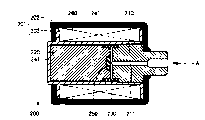
Here, Fig. 5 and Fig. 6 represent the sectional structure of electromagnetic gas valve 200 in the past.Support 201 has rack body 202 and bracket cover 203, in this rack body 202, is equipped with coil carrier 241, is equipped with coil case 260 between the inner peripheral surface of the outer circumferential face of coil carrier 241 and rack body 202.In addition, in the inside of coil carrier 241, coaxially be provided with secured core 210 and, between secured core 210 and movable core 220, be equipped with the helical spring 230 that loads to the direction that will separate between the two as the movable core 220 of slider.Secured core is provided with air flue 211, relative with movable core 220 to the position be provided with the nozzle (air outlet slit portion) 212 of convex, movable core 220 relative with nozzle 212 to the position on be embedded with rubber gasket 250.
At common state (electric current does not flow through the state of coil case 260), as shown in Figure 6, be in the rubber gasket 250 of the movable core 220 by helical spring 230 and the nozzle 212 separated states of secured core 210, becoming can be from the state of air flue 211 discharged air.On the other hand, in off position, as shown in Figure 7, by making electric current flow through coil case 260, by the excitation of coil case 260 and produce magnetic flux, movable core 220 is adsorbed on the secured core 110, push nozzle 212 by rubber gasket 250, with air flue 211 sealings.
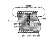
Here, under the situation of considering the overall dimensions that reduces the air valve 220 that is made of said structure, people consider as shown in Figure 8, reduce the external diameter of support 201, on the other hand, in order to ensure the volume of coil case 260, reduce the external diameter φ 1 of secured core 110 and movable core 120.But also can't reduce the internal diameter of nozzle 212 according to the relation of air mass flow, also can't change the diameter of the rubber gasket 250 that is used for valve nozzles 212.Thus, as shown in Figure 9, the magnetic pole area of the movable core 220 around the rubber gasket 250 diminishes.Thus, magnetic flux M concentrates on the narrow and small zone around the rubber gasket 250, and magnetic resistance increases, the magnetic circuit efficiency variation, and driving force reduces, and consequently, adsorption force that might 210 pairs of movable cores 220 of secured core extremely reduces.So, take place from the situation of nozzle 212 gas leakage.On the other hand, in the structure of miniaturization shown in Figure 8,, must increase electric current, the result who causes current value to increase like this in order to obtain and in the past identical adsorption force.
In addition, as shown in Figure 10, the end face part with secured core 110 opposite sides of movable core 220 is in the state that the resinous coil carrier 241 that constituted by the material by nonmagnetic material covers.Thus, owing between bracket cover 203 that constitutes magnetic circuit and movable core 220, produce the gap L 1 that is equivalent to resin thickness,, become the factor that magnetic circuit efficient reduces so rise at the magnetic resistance of this gap L 1.
Summary of the invention
The problem that problem that the problem to be solved in the present invention produces when making the electromagnetic gas valve miniaturization, driving force descends and magnetic circuit efficiency descend.So, the object of the present invention is to provide a kind of electromagnetic gas valve, this electromagnetic gas valve has the structure that can improve magnetic efficiency by reduce the space that produces between support and movable core.
Based on electromagnetic gas valve of the present invention, comprising: secured core, it is fixed in the inside of the support that is made of the magnetic material; Movable core, it is ccontaining by the coil carrier that constitutes with the nonmagnetic material material in the inside of above-mentioned support, and can move vertically; Gas outlet, it is arranged at the said fixing iron core relative with above-mentioned movable core to the subtend face on; Sealing gasket, it is arranged at above-mentioned movable core relative with the above-mentioned gas outlet to the subtend face on; Deceleration loading device, it is used for above-mentioned movable core is loaded towards the direction of leaving from the said fixing iron core; Coil case, it is used to produce magnetic flux, produce the magnetic circuit that above-mentioned movable core is adsorbed in the power of said fixing core side so that form, wherein, between the side and above-mentioned coil carrier of above-mentioned movable core, be provided with and be used to limit the stop area of above-mentioned movable core towards the displacement distance of the direction of leaving from the said fixing iron core, above-mentioned support has rack body and bracket cover, this bracket cover is with the end face sealing of the opposition side of a side of ccontaining above-mentioned movable core, above-mentioned bracket cover is provided with the outstanding laterally opening portion of above-mentioned movable core, and by above-mentioned support, above-mentioned movable core, the said fixing iron core constitutes above-mentioned magnetic circuit, and this magnetic circuit is used to produce the power that above-mentioned movable core is moved.
According to based on electromagnetic gas valve of the present invention, between movable core and side and coil carrier, be provided with and be used to limit the stop area of movable core towards the displacement distance of the direction of leaving from secured core, bracket cover is provided with the outstanding laterally opening portion of movable core, thus, gap (distance) between the end face of the opening portion of bracket cover and the side of movable core can only be set to slidably clearance distance of movable core, thus, can reduce this gap (distance) as much as possible.Consequently, reduce magnetic resistance this gap (distance), between bracket cover and the movable core, can improve magnetic circuit efficient.
With reference to accompanying drawing,, be more prone to draw aforementioned and other purpose, feature and aspect and advantage of the present invention according to following specific descriptions of the present invention.
Description of drawings
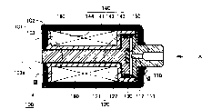
Fig. 1 is the sectional view of the structure of the electromagnetic gas valve of this form of implementation of expression;
Fig. 2 is the local amplification view with the II region surrounded among Fig. 1;
Fig. 3 is the local amplification view with the III region surrounded among Fig. 1;
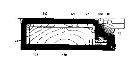
Fig. 4 is for representing that the electromagnetic gas valve with this form of implementation is the Magnetic flux density of model and the figure of magnetic flux analysis result;
Fig. 5 is the sectional view of the structure of expression electromagnetic gas valve in the past;
Fig. 6 is the local amplification view (open mode) of the structure of expression electromagnetic gas valve in the past;
Fig. 7 is the local amplification view (closed condition) of the structure of expression electromagnetic gas valve in the past;
Fig. 8 is the sectional view of the problem of expression electromagnetic gas valve in the past;
Fig. 9 is the local amplification view of first problem of expression electromagnetic gas valve in the past;
Figure 10 is the local amplification view of second problem of expression electromagnetic gas valve in the past.
Embodiment
Below with reference to Fig. 1~Fig. 3, the structure of the electromagnetic gas valve of the invention process form is described.In addition, Fig. 1 is the sectional view of the structure of the electromagnetic gas valve of this form of implementation of expression, and Fig. 2 is the local amplification view with the II region surrounded among Fig. 1, and Fig. 3 is the local amplification view with the III region surrounded among Fig. 1.
At first, with reference to Fig. 1, the structure of the electromagnetic gas valve 100 of this form of implementation is described.This electromagnetic gas valve 100 comprises the support 101 that is made of the magnetic material, this support 101 comprise rack body 102, with bracket cover 103 with the sealing of one of them end.The magnetic material that constitutes rack body 102 and bracket cover 103 for example adopts SUYB-1 (electromagnetism iron and steel) etc.Another distolateral internal fixation at rack body 102 has secured core 110, and its part is outstanding laterally.In secured core 110, be provided with air flue 111, relative with movable core described later 120 to the position be provided with the nozzle (air outlet slit portion) 112 of convex.In addition, in the inside of rack body 102, be equipped with movable core 120, this movable core 120 is ccontaining by the coil carrier 140 that constitutes with the nonmagnetic material material, and can move vertically.
In addition, in the space between the inner peripheral surface of the outer circumferential face of the axle region 141 of coil carrier 140 and rack body 102, in order to be formed for producing the magnetic circuit that movable core 120 is adsorbed in the power of secured core 110 sides, be equipped with the coil case 160 that is used to produce magnetic flux.The winding wire diameter of this coil case 160 is about Φ 0.1mm, and the number of turn is about 1000 circles, and resistance is about 30 Ω, and coil current is about 80mA.
In addition, with reference to Fig. 1 and Fig. 3, bracket cover 103 is provided with opening portion 103a, and the end of the axial region 121 of movable core 120 is outstanding laterally from this opening portion 103a.In addition, in the axle region 141 of coil carrier 140 and the intersection region in bracket cover zone 144, be provided with the protuberance 141a that is projected into bracket cover 103 sides, bracket cover 103 is provided with the recess 103b that admits this protuberance 141a.
(effect, effect)
In the electromagnetic gas valve 100 that constitutes by said structure, when electric current flows through coil case 160, as shown in Figure 2, lip part 122 at movable core 120, owing to around rubber gasket 150, can guarantee enough magnetic pole areas, so magnetic resistance diminishes, towards flowing smoothly of the magnetic flux M of secured core 110.In addition,, be extended with the extending portion zone 143 of the coil carrier 140 that the material by nonmagnetic material constitutes in the circumferential lateral surface of the lip part 122 of movable core 120, thus, according to towards the mode of secured core 110 sides magnetic flux M being led really.
Here as can be known, the magnetic resistance in the gap (L) between the lip part 122 of secured core 110 and movable core 120 is represented by following formula (1).
R=L/ (S μ
o) ... formula (1)
(magnetic resistance: R, gap clearance is from L, magnetic pole area: S, the relative permeability of air: μ
o)
According to this formula (1) as can be known, in order to reduce magnetic resistance R, improve magnetic circuit efficient, needing increases magnetic pole area (S), guarantees driving force.The present invention is when carrying out the miniaturization of electromagnetic gas valve, be conceived to this, realize by following mode, promptly, make the flange-type of movable core 120 for constituting by axial region 121 and lip part 122, even thereby reduce the diameter (φ 1) of movable core 120 in order to ensure winding volume, do not reduce yet relative with fixed electrode to the magnetic pole area, can fully guarantee to be used for the driving force of valve nozzles 112.
In addition, by the ccontaining coil case 160 in space between the inner peripheral surface of coil carrier 140 axle region 141 that center on movable core 120 axial regions 121 and rack body 102, when guaranteeing the coil portion volume, also can reduce the outside dimension of support 101, consequently, can make electromagnetic gas valve 100 miniaturizations.
In addition, by lip part 122 is set on movable core 120, in addition, the lip part zone 142 of extending along lip part 122 is set on coil carrier 140, and stop area is set, this stop area, at loading force by helical spring 130, and movable core 120 contact with the lip part zone 142 of faces secured core 110 opposite sides and coil carrier 140 by lip part 122 when coil carrier 140 moves, and qualification movable core 120 is towards the displacement distance of the direction of leaving from secured core 110.
Thus, owing to need not the movable core end is limited displacement distance, so the end of the axial region 121 of movable core 120 is given prominence to laterally from the opening portion 103a of bracket cover 103.Consequently, as shown in Figure 3, gap between the side of the end face of the opening portion 103a of bracket cover 103 and the axial region 121 of movable core 120 (distance: L2) can only be set to slidably clearance distance of movable core 120, like this, can reduce this gap (distance: L2) as much as possible.Consequently, reduce magnetic resistance (with reference to formula 1) this gap (distance), between bracket cover 103 and the movable core 120, improve magnetic circuit efficient.
In addition, preferably between support 103 and coil carrier 140, be provided with above-mentioned protuberance 141a, with the recess 103b that admits this protuberance 141a, as the locating area that carries out location between the two.
In addition, Fig. 4 represents that the electromagnetic gas valve 10 with this form of implementation is the Magnetic flux density and the magnetic flux analysis result of model.This analysis result is 1/4 cae analysis model.Show also that according to this analysis result the magnetic flux M in the gap between the side of the end face of the lip part 122 of movable core 120 and the opening portion 103a of bracket cover 103 and the axial region 121 of movable core 120 is extremely unconcentrated, and successfully flow.
Also have, in above-mentioned form of implementation, be the lip part 122 that adopts movable core 120, form stop area with the lip part zone 142 of coil carrier 140, but, in order to limit the displacement distance of movable core 120 towards the direction of leaving from secured core 110, also can be arranged between the side of movable core 120 and the coil carrier 140 zone of engaging mutually in addition, should engage regional as stop area.
Though invention has been described particularly and diagram,, understand that obviously foregoing description only is to provide by diagram and form of implementation, should not consider that the spirit and scope of the invention only limit by accompanying Claim according to limiting mode.
Claims (5)
1. electromagnetic gas valve comprises:
Secured core (110), it is fixed in the inside of the support (101) that is made of the magnetic material; Movable core (120), it is ccontaining by the coil carrier that constitutes with the nonmagnetic material material (140) in the inside of above-mentioned support (101), and can move vertically; Gas outlet (111), it is arranged at said fixing iron core (110) relative with above-mentioned movable core (120) to the subtend face on; Sealing gasket (150), it is arranged at above-mentioned movable core (120) relative with above-mentioned gas outlet (110) to the subtend face on; Deceleration loading device (130), it is used for above-mentioned movable core (120) is loaded towards the direction of leaving from said fixing iron core (110); Coil case (160), it is used to produce magnetic flux, produces the magnetic circuit that above-mentioned movable core (120) is adsorbed in the power of said fixing iron core (110) side so that form, it is characterized in that,
Between the side and above-mentioned coil carrier (140) of above-mentioned movable core (120), be provided with and be used to limit the stop area of above-mentioned movable core (120) towards the displacement distance of the direction of leaving from said fixing iron core (110),
Above-mentioned support (101) has rack body (102) and bracket cover (103), and this bracket cover (103) seals the end face of the opposition side of a side of ccontaining above-mentioned movable core (120),
Above-mentioned bracket cover (103) is provided with the outstanding laterally opening portion (103a) of above-mentioned movable core (120),
Constitute above-mentioned magnetic circuit by above-mentioned support (101), above-mentioned movable core (120), said fixing iron core (110), this magnetic circuit is used for producing the power that above-mentioned movable core (120) is moved.
2. electromagnetic gas valve according to claim 1 is characterized in that, above-mentioned movable core (120) has the outstanding lip part (122) to sidepiece foreign side in said fixing iron core (110) side,
Above-mentioned coil carrier (140) is along the circumferential lateral surface setting of above-mentioned movable core (120),
Above-mentioned stop area, when above-mentioned movable core (120) is mobile along above-mentioned coil carrier (140), contact with above-mentioned coil carrier (140) with face said fixing iron core (110) opposition side by above-mentioned lip part (122), limit the displacement distance of above-mentioned movable core (120) towards the direction of leaving from said fixing iron core (110).
3. electromagnetic gas valve according to claim 1 is characterized in that, between above-mentioned bracket cover (103) and above-mentioned coil carrier (140), is provided with the locating area that carries out location between the two.
4. electromagnetic gas valve according to claim 1 is characterized in that, above-mentioned movable core (120) has: the lip part (122) that is formed by first diameter; The axial region (121) that forms by second diameter littler than first diameter,
Above-mentioned lip part (122) is provided with above-mentioned sealing gasket (150), in the space between the inner peripheral surface of above-mentioned coil carrier (140) that centers on above-mentioned axial region (121) and above-mentioned support (101), is equipped with above-mentioned coil case (160) simultaneously.
5. electromagnetic gas valve according to claim 1 is characterized in that, between the inner peripheral surface of the circumferential lateral surface of above-mentioned lip part (122) and above-mentioned support (101), is provided with the extending portion zone (143) of above-mentioned coil carrier (140) in the mode of extending.
Applications Claiming Priority (2)
| Application Number | Priority Date | Filing Date | Title |
|---|---|---|---|
| JP2004204814A JP4576906B2 (en) | 2004-07-12 | 2004-07-12 | Solenoid air valve |
| JP2004204814 | 2004-07-12 |
Publications (2)
| Publication Number | Publication Date |
|---|---|
| CN1721743A CN1721743A (en) | 2006-01-18 |
| CN100394084C true CN100394084C (en) | 2008-06-11 |
Family
ID=35044898
Family Applications (1)
| Application Number | Title | Priority Date | Filing Date |
|---|---|---|---|
| CNB2005100835613A Expired - Fee Related CN100394084C (en) | 2004-07-12 | 2005-07-11 | Solenoid air valve |
Country Status (7)
| Country | Link |
|---|---|
| US (1) | US7095304B2 (en) |
| EP (2) | EP1617117B1 (en) |
| JP (1) | JP4576906B2 (en) |
| KR (1) | KR100674323B1 (en) |
| CN (1) | CN100394084C (en) |
| DE (1) | DE602005010152D1 (en) |
| ES (1) | ES2310786T3 (en) |
Families Citing this family (20)
| Publication number | Priority date | Publication date | Assignee | Title |
|---|---|---|---|---|
| JP4576908B2 (en) * | 2004-07-13 | 2010-11-10 | オムロンヘルスケア株式会社 | Solenoid air valve |
| JP4511489B2 (en) * | 2006-04-11 | 2010-07-28 | 日本精密測器株式会社 | Electric exhaust valve and blood pressure monitor |
| CN100545490C (en) * | 2006-04-11 | 2009-09-30 | 日本精密测器株式会社 | Electric-powered air release valve and sphygmomanometer |
| DE202006006825U1 (en) * | 2006-04-27 | 2007-08-30 | Bürkert Werke GmbH & Co. KG | Valve with an electromagnetic drive |
| FR2916254B3 (en) * | 2007-05-16 | 2009-04-17 | Parker Lucifer Sa Sa | ELECTROVALVE HAS A NUMBER OF MANEUVER |
| US7432820B1 (en) | 2007-05-31 | 2008-10-07 | Phan Charlie D | Sound-flag synchronized action controller |
| WO2009084353A1 (en) | 2007-12-28 | 2009-07-09 | Hosiden Corporation | Solenoid valve |
| WO2009108533A2 (en) * | 2008-02-19 | 2009-09-03 | Continental Automotive Systems Us, Inc. | Tau-omega armature-stator configuration of long stroke solenoid |
| DE102009029565A1 (en) * | 2009-09-18 | 2011-03-31 | Robert Bosch Gmbh | Magnetic assembly for a solenoid valve and corresponding solenoid valve |
| JP6089517B2 (en) * | 2012-09-11 | 2017-03-08 | オムロンヘルスケア株式会社 | Flow rate control valve and blood pressure information measuring apparatus provided with the same |
| DE102013202632A1 (en) * | 2013-02-19 | 2014-08-21 | Robert Bosch Gmbh | Valve with simplified guidance |
| JP6248439B2 (en) | 2013-07-10 | 2017-12-20 | オムロンヘルスケア株式会社 | Electromagnetic valve and electronic blood pressure monitor having the same |
| CN105489343A (en) * | 2016-01-20 | 2016-04-13 | 海宁市飞腾电子有限公司 | Electromagnetic coil |
| CN105931795A (en) * | 2016-04-08 | 2016-09-07 | 韩江 | Soft magnetic ferrite core and method for manufacturing same |
| JP6724565B2 (en) * | 2016-05-31 | 2020-07-15 | オムロンヘルスケア株式会社 | Flow control valve and blood pressure information measuring device |
| CN109786061A (en) * | 2017-11-10 | 2019-05-21 | 浙江盾安禾田金属有限公司 | A kind of electromagnetic coil for air-conditioning |
| GB2569588A (en) * | 2017-12-20 | 2019-06-26 | Delphi Automotive Systems Lux | Direct acting fuel injector |
| CN108050292A (en) * | 2018-01-24 | 2018-05-18 | 太仓源凯汽车配件有限公司 | A kind of automatically controlled by-passing valve of high-performance |
| CN108468853B (en) * | 2018-05-25 | 2024-08-16 | 宁波奉化胜雄机电科技有限公司 | Air pump valve and assembly method thereof |
| TWI756655B (en) | 2020-03-30 | 2022-03-01 | 比理恩設計有限公司 | Valve body, electromagnet switch valve and bed structure |
Citations (4)
| Publication number | Priority date | Publication date | Assignee | Title |
|---|---|---|---|---|
| US4459991A (en) * | 1980-02-18 | 1984-07-17 | Asulab A.G. | Blood pressure measuring equipment |
| JPH09135817A (en) * | 1995-11-16 | 1997-05-27 | Fukuda Denshi Co Ltd | Flow control valve and automatic sphygmomanometer equipped with the flow control valve |
| US5655746A (en) * | 1994-03-17 | 1997-08-12 | Eaton Corporation | Two-port fluid solenoid valve |
| DE29707905U1 (en) * | 1997-05-02 | 1998-08-27 | Honeywell B.V., Amsterdam | Solenoid valve and its application for controlling the gas supply to a burner |
Family Cites Families (12)
| Publication number | Priority date | Publication date | Assignee | Title |
|---|---|---|---|---|
| JPS4724004Y1 (en) * | 1968-10-23 | 1972-07-31 | ||
| GB2064720B (en) | 1979-12-07 | 1983-06-02 | Lucas Industries Ltd | Solenoid operated fluid pressure control valve |
| ZA805725B (en) * | 1979-12-07 | 1981-09-30 | Lucas Industries Ltd | Fluid pressure control valve |
| JPH0237002Y2 (en) * | 1984-12-25 | 1990-10-08 | ||
| JPS6324471U (en) * | 1986-07-31 | 1988-02-18 | ||
| JPH0229504U (en) * | 1988-08-12 | 1990-02-26 | ||
| JPH08203730A (en) * | 1995-01-26 | 1996-08-09 | Matsushita Electric Works Ltd | Solenoid |
| US5992461A (en) * | 1998-08-18 | 1999-11-30 | Numatics, Incorporated | Solenoid valve housing |
| JP3770733B2 (en) * | 1998-09-22 | 2006-04-26 | テルモ株式会社 | Constant speed exhaust valve |
| JP2001317648A (en) * | 2000-03-02 | 2001-11-16 | Fuji Koki Corp | Solenoid valve |
| JP2002276839A (en) * | 2001-03-14 | 2002-09-25 | Staf Corp | Air valve |
| JP2003225213A (en) * | 2002-02-06 | 2003-08-12 | Aitekku:Kk | Apparatus for measuring blood pressure and electromagnetic type exhaust valve |
-
2004
- 2004-07-12 JP JP2004204814A patent/JP4576906B2/en not_active Expired - Fee Related
-
2005
- 2005-07-06 DE DE602005010152T patent/DE602005010152D1/en active Active
- 2005-07-06 EP EP05014670A patent/EP1617117B1/en not_active Not-in-force
- 2005-07-06 ES ES05014670T patent/ES2310786T3/en active Active
- 2005-07-06 EP EP07150305A patent/EP1898137A1/en not_active Withdrawn
- 2005-07-08 US US11/176,574 patent/US7095304B2/en active Active
- 2005-07-11 KR KR1020050062063A patent/KR100674323B1/en active IP Right Grant
- 2005-07-11 CN CNB2005100835613A patent/CN100394084C/en not_active Expired - Fee Related
Patent Citations (4)
| Publication number | Priority date | Publication date | Assignee | Title |
|---|---|---|---|---|
| US4459991A (en) * | 1980-02-18 | 1984-07-17 | Asulab A.G. | Blood pressure measuring equipment |
| US5655746A (en) * | 1994-03-17 | 1997-08-12 | Eaton Corporation | Two-port fluid solenoid valve |
| JPH09135817A (en) * | 1995-11-16 | 1997-05-27 | Fukuda Denshi Co Ltd | Flow control valve and automatic sphygmomanometer equipped with the flow control valve |
| DE29707905U1 (en) * | 1997-05-02 | 1998-08-27 | Honeywell B.V., Amsterdam | Solenoid valve and its application for controlling the gas supply to a burner |
Also Published As
| Publication number | Publication date |
|---|---|
| US20060006967A1 (en) | 2006-01-12 |
| DE602005010152D1 (en) | 2008-11-20 |
| KR100674323B1 (en) | 2007-01-24 |
| JP2006029362A (en) | 2006-02-02 |
| ES2310786T3 (en) | 2009-01-16 |
| EP1617117A1 (en) | 2006-01-18 |
| US7095304B2 (en) | 2006-08-22 |
| JP4576906B2 (en) | 2010-11-10 |
| KR20060050030A (en) | 2006-05-19 |
| EP1617117B1 (en) | 2008-10-08 |
| CN1721743A (en) | 2006-01-18 |
| EP1898137A1 (en) | 2008-03-12 |
Similar Documents
| Publication | Publication Date | Title |
|---|---|---|
| CN100394084C (en) | Solenoid air valve | |
| CN100394085C (en) | Solenoid air valve | |
| JP4511489B2 (en) | Electric exhaust valve and blood pressure monitor | |
| JP5979790B2 (en) | Pilot operated solenoid valve | |
| JP5816654B2 (en) | Valve with electromagnetic drive | |
| US20120292544A1 (en) | Solenoid for electromagnetic valve | |
| CN103185163A (en) | Flow control proportioning valve | |
| CN111712661B (en) | Electromagnetic valve, sphygmomanometer and equipment | |
| JP2006029362A5 (en) | ||
| CN205503997U (en) | Burnt gas proportion valve | |
| CN106979357B (en) | Electromagnetic valve | |
| KR101749735B1 (en) | A solenoid valve | |
| JPS58214084A (en) | Solenoid valve | |
| CN220505838U (en) | High-precision flow control proportional electromagnetic valve | |
| CN218935314U (en) | High-pressure miniature electromagnetic valve | |
| JPH01320383A (en) | Solenoid valve | |
| JP6493586B2 (en) | Solenoid device and manufacturing method thereof | |
| CN117287549A (en) | Electromagnetic valve and equipment | |
| JPH09178021A (en) | Magnetic circuit construction of coil for solenoid valve | |
| JPH0118943Y2 (en) | ||
| JPS59105667U (en) | Manual switching device for solenoid valve | |
| CN117090949A (en) | High-precision flow control proportional electromagnetic valve | |
| CN115451177A (en) | Pneumatic high-speed switch valve | |
| JP2005144140A (en) | Flowmeter | |
| JP2000130632A (en) | Solenoid valve |
Legal Events
| Date | Code | Title | Description |
|---|---|---|---|
| C06 | Publication | ||
| PB01 | Publication | ||
| C10 | Entry into substantive examination | ||
| SE01 | Entry into force of request for substantive examination | ||
| C14 | Grant of patent or utility model | ||
| GR01 | Patent grant | ||
| CF01 | Termination of patent right due to non-payment of annual fee | ||
| CF01 | Termination of patent right due to non-payment of annual fee |
Granted publication date: 20080611 |