CN100382475C - Transmitting device and receiving device - Google Patents
Transmitting device and receiving device Download PDFInfo
- Publication number
- CN100382475C CN100382475C CNB038105551A CN03810555A CN100382475C CN 100382475 C CN100382475 C CN 100382475C CN B038105551 A CNB038105551 A CN B038105551A CN 03810555 A CN03810555 A CN 03810555A CN 100382475 C CN100382475 C CN 100382475C
- Authority
- CN
- China
- Prior art keywords
- received signal
- code element
- time group
- reflector
- code
- Prior art date
- Legal status (The legal status is an assumption and is not a legal conclusion. Google has not performed a legal analysis and makes no representation as to the accuracy of the status listed.)
- Expired - Fee Related
Links
Images


Classifications
-
- H—ELECTRICITY
- H04—ELECTRIC COMMUNICATION TECHNIQUE
- H04B—TRANSMISSION
- H04B7/00—Radio transmission systems, i.e. using radiation field
- H04B7/02—Diversity systems; Multi-antenna system, i.e. transmission or reception using multiple antennas
- H04B7/04—Diversity systems; Multi-antenna system, i.e. transmission or reception using multiple antennas using two or more spaced independent antennas
- H04B7/06—Diversity systems; Multi-antenna system, i.e. transmission or reception using multiple antennas using two or more spaced independent antennas at the transmitting station
- H04B7/0613—Diversity systems; Multi-antenna system, i.e. transmission or reception using multiple antennas using two or more spaced independent antennas at the transmitting station using simultaneous transmission
- H04B7/0667—Diversity systems; Multi-antenna system, i.e. transmission or reception using multiple antennas using two or more spaced independent antennas at the transmitting station using simultaneous transmission of delayed versions of same signal
- H04B7/0669—Diversity systems; Multi-antenna system, i.e. transmission or reception using multiple antennas using two or more spaced independent antennas at the transmitting station using simultaneous transmission of delayed versions of same signal using different channel coding between antennas
-
- H—ELECTRICITY
- H04—ELECTRIC COMMUNICATION TECHNIQUE
- H04L—TRANSMISSION OF DIGITAL INFORMATION, e.g. TELEGRAPHIC COMMUNICATION
- H04L1/00—Arrangements for detecting or preventing errors in the information received
- H04L1/004—Arrangements for detecting or preventing errors in the information received by using forward error control
- H04L1/0045—Arrangements at the receiver end
- H04L1/0047—Decoding adapted to other signal detection operation
- H04L1/0048—Decoding adapted to other signal detection operation in conjunction with detection of multiuser or interfering signals, e.g. iteration between CDMA or MIMO detector and FEC decoder
-
- H—ELECTRICITY
- H04—ELECTRIC COMMUNICATION TECHNIQUE
- H04L—TRANSMISSION OF DIGITAL INFORMATION, e.g. TELEGRAPHIC COMMUNICATION
- H04L1/00—Arrangements for detecting or preventing errors in the information received
- H04L1/004—Arrangements for detecting or preventing errors in the information received by using forward error control
- H04L1/0045—Arrangements at the receiver end
- H04L1/0054—Maximum-likelihood or sequential decoding, e.g. Viterbi, Fano, ZJ algorithms
-
- H—ELECTRICITY
- H04—ELECTRIC COMMUNICATION TECHNIQUE
- H04L—TRANSMISSION OF DIGITAL INFORMATION, e.g. TELEGRAPHIC COMMUNICATION
- H04L1/00—Arrangements for detecting or preventing errors in the information received
- H04L1/004—Arrangements for detecting or preventing errors in the information received by using forward error control
- H04L1/0056—Systems characterized by the type of code used
- H04L1/0071—Use of interleaving
-
- H—ELECTRICITY
- H04—ELECTRIC COMMUNICATION TECHNIQUE
- H04L—TRANSMISSION OF DIGITAL INFORMATION, e.g. TELEGRAPHIC COMMUNICATION
- H04L1/00—Arrangements for detecting or preventing errors in the information received
- H04L1/02—Arrangements for detecting or preventing errors in the information received by diversity reception
- H04L1/06—Arrangements for detecting or preventing errors in the information received by diversity reception using space diversity
- H04L1/0618—Space-time coding
- H04L1/0625—Transmitter arrangements
-
- H—ELECTRICITY
- H04—ELECTRIC COMMUNICATION TECHNIQUE
- H04L—TRANSMISSION OF DIGITAL INFORMATION, e.g. TELEGRAPHIC COMMUNICATION
- H04L1/00—Arrangements for detecting or preventing errors in the information received
- H04L1/02—Arrangements for detecting or preventing errors in the information received by diversity reception
- H04L1/06—Arrangements for detecting or preventing errors in the information received by diversity reception using space diversity
- H04L1/0618—Space-time coding
- H04L1/0631—Receiver arrangements
-
- H—ELECTRICITY
- H04—ELECTRIC COMMUNICATION TECHNIQUE
- H04L—TRANSMISSION OF DIGITAL INFORMATION, e.g. TELEGRAPHIC COMMUNICATION
- H04L1/00—Arrangements for detecting or preventing errors in the information received
- H04L1/02—Arrangements for detecting or preventing errors in the information received by diversity reception
- H04L1/06—Arrangements for detecting or preventing errors in the information received by diversity reception using space diversity
- H04L1/0618—Space-time coding
- H04L1/0637—Properties of the code
- H04L1/065—Properties of the code by means of convolutional encoding
-
- H—ELECTRICITY
- H04—ELECTRIC COMMUNICATION TECHNIQUE
- H04L—TRANSMISSION OF DIGITAL INFORMATION, e.g. TELEGRAPHIC COMMUNICATION
- H04L25/00—Baseband systems
- H04L25/02—Details ; arrangements for supplying electrical power along data transmission lines
- H04L25/0202—Channel estimation
- H04L25/0204—Channel estimation of multiple channels
-
- H—ELECTRICITY
- H04—ELECTRIC COMMUNICATION TECHNIQUE
- H04L—TRANSMISSION OF DIGITAL INFORMATION, e.g. TELEGRAPHIC COMMUNICATION
- H04L25/00—Baseband systems
- H04L25/02—Details ; arrangements for supplying electrical power along data transmission lines
- H04L25/0202—Channel estimation
- H04L25/024—Channel estimation channel estimation algorithms
- H04L25/0242—Channel estimation channel estimation algorithms using matrix methods
-
- H—ELECTRICITY
- H04—ELECTRIC COMMUNICATION TECHNIQUE
- H04L—TRANSMISSION OF DIGITAL INFORMATION, e.g. TELEGRAPHIC COMMUNICATION
- H04L25/00—Baseband systems
- H04L25/02—Details ; arrangements for supplying electrical power along data transmission lines
- H04L25/03—Shaping networks in transmitter or receiver, e.g. adaptive shaping networks
- H04L25/03006—Arrangements for removing intersymbol interference
- H04L2025/03592—Adaptation methods
- H04L2025/03598—Algorithms
- H04L2025/03605—Block algorithms
Landscapes
- Engineering & Computer Science (AREA)
- Computer Networks & Wireless Communication (AREA)
- Signal Processing (AREA)
- Power Engineering (AREA)
- Artificial Intelligence (AREA)
- Mathematical Physics (AREA)
- Physics & Mathematics (AREA)
- Radio Transmission System (AREA)
- Error Detection And Correction (AREA)
- Radio Relay Systems (AREA)
- Electrical Discharge Machining, Electrochemical Machining, And Combined Machining (AREA)
- Application Of Or Painting With Fluid Materials (AREA)
- Detection And Prevention Of Errors In Transmission (AREA)
Abstract
A redundancy-adding coder with a code rate greater or similar to 0.5 is used in a transmitting/receiving concept in order to obtain two data flows for two different transmitters which are arranged in different spatial positions. Both transmitters transmit in the same frequency bands. In the receiving element, the receiving signal is scanned by a first scanner (40a) in a synchronous manner with respect to the first transmitter by a second scanner (40b) in a synchronous manner with respect to the second transmitter in order to obtain a first and a second receiving signal which are guided to a Trellis-Decoder (54) in order to obtain a decoded first (56a) and second (56b) receiving-sub-group of code units which are in turn guided to a calculation device (58) in order to calculate the interference signals which are then combined (60a, 60b) with the corresponding receiving signal for interference reduction (60). The iterative concept enables an interference reduction for receiving signals which are produced by two spatially separate transmitting transmitters, both transmitting in the same frequency band. The receiver concept displays rapid convergence and thus enables both transmitters to transmit in the same frequency band, resulting in a reduction of the necessary band width which is reduced by up to half in comparison to a corresponding transmitter concept, wherein the first and second transmitter transmit at different frequencies.
Description
Technical field
The invention relates to a digital communication technology, and particularly about being used for the idea of message communication, it is to see through to have the weak channel of a storage, for example wireless channel.
Background technology
WO 00/367783 discloses a kind of apparatus and method that are used to launch information, and the apparatus and method that are used to the information that receives.The described device that is used to launch information is to comprise an information source, have yard speed less than 1/2 one redundancy-addition encoder, a separator, be used for the output of described encoder is separated into two different data streams, wherein the emission of a data flow is to see through one first channel, and the emission of another data flow is to see through a second channel.This redundancy-addition encoder is finished an error correction of advancing, and it is the decoder that is used to an acceptor side, to guarantee good receiving quality.
Described first and second channel is different, is different on its space, and integrates a time variation function, that is sees through the information that described first channel is launched, and sees through another channels transmit in next time point once more.
Have two receivers to exist at described receiver-side, it is also inequality each other, is used on the one hand receive see through the signal that described first channel is launched, and is used to receive the signal through being launched on the other hand on the other hand.Use a colligator,, and it is delivered to a decoder, for example be set at a Viterbi (Viterbi) decoder, and its output valve is admitted to Li De Saloman (Reed-Solomon) decoder the combination of described receiver output signal.
Known diverse location dispose two satellites as reflector transmitting/receiving system, be on different frequency bands, to launch.Because satellite received signal is at different frequency bands, and the usable frequency selection mode receives, so can simple zones divide the signal from different satellites.
Yet in fact the shortcoming of this notion is to need two complete frequency bands, that is first satellite is in the emission of first frequency band, and second satellite is to launch at the second frequency band.
Yet generally speaking, the bandwidth of send channel is very precious, uses required bandwidth and both expensive so only can obtain a point bandwidth or usually on using.Thereby significantly increase the cost of system.Particularly on propagate using, in receiving system, must be divided into the development of reflector and satellite and set up., thereby cause the increase of cost.Yet particularly in propagating the competitive market of receiver, difference in selling prices slightly can cause a system to be accepted by market and another system is defeated and disappears on market.
Summary of the invention
The purpose of this invention is to provide a kind of more effective cost-effective transmission/reception.This purpose can emitter disclosed in this invention, launching technique, receiving system or method of reseptance and reaching.
The present invention discloses a kind of receiving system that is used to receive a replacement received signal, one first and 1 second replacement that transmits that described replacement received signal is launched corresponding to one first reflector and one second reflector, described second reflector is be disposed at described first reflector long-range, it is in identical frequency band that wherein said first and second transmits, wherein be to use the code element of one first emission time group and produce described first and transmit, wherein be to use the code element of one second emission time group and produce described second and transmit, the a plurality of code elements of the common representative of the code element of the code element of the wherein said first emission time group and the described second emission time group, it is the information character with a plurality of information units, produce by a redundant addition coding, described receiving system comprises: the device of the described replacement received signal that is used to take a sample, it is synchronized with described first reflector, to obtain and the first one first relevant received signal that transmits of being launched, and described device is to be used for and the take a sample received signal of described replacement of described second transmitter synchronization, to obtain and the second one second relevant received signal that transmits of being launched; One code translator, be used to decipher described first and second received signal, to obtain the code element of one first reception time group, it is relevant with the code element of the described first emission time group, and decipher described first and second received signal, to obtain the code element of one second reception time group, it is relevant with the code element of the described second emission time group; One calculation element in order to by using described second code element that receives time group to calculate one first interference signal, and uses described first to receive the code element of time group and calculate one second interference signal; One disturbs the reduction device, is used in conjunction with described first interference signal and described first received signal, and is used in conjunction with described second interference signal and described second received signal, to obtain first received signal of improving and second received signal of improving; An and control device, be used to control described code translator, therefore first received signal of described improvement and second received signal of described improvement have similarly been deciphered, and based on first received signal of described improvement and second received signal of described improvement, output device has the described information character of described a plurality of information units.
The present invention also discloses a kind of method that is used to receive a replacement received signal, described replacement received signal is corresponding to first and second replacement that transmits of being launched by one first reflector and one second reflector respectively, described second reflector is be disposed at described first reflector long-range, it is in identical frequency band that wherein said first and second transmits, wherein be to use the code element of one first emission time group and produce described first and transmit, wherein be to use the code element of one second emission time group and produce described second and transmit, the a plurality of code elements of the common representative of the code element of the code element of the wherein said first emission time group and the described second emission time group, it is the information character with a plurality of information units, produce by a redundant addition coding, described method comprises: be synchronized with the described first reflector described shared received signal of taking a sample, to obtain and the first one first relevant received signal that transmits of being launched; Get and be synchronized with the described second reflector described shared received signal of taking a sample, to obtain and the second one second relevant received signal that transmits of being launched; Decipher described first and second received signal, to obtain the code element of one first reception time group, it is relevant with the code element of the described first emission time group; Decipher described first and second received signal, to obtain the code element of one second reception time group, it is relevant with the code element of the described second emission time group; Calculate one first interference signal, it is to use described second to receive the code element of time group, and calculates one second interference signal, and it is to use the code element of the described first reception time group; In conjunction with described first interference signal and described first received signal, and,, disturb reduction to obtain one to obtain first received signal of improving and second received signal of improving in conjunction with described second interference signal and described second received signal; And decipher first received signal of described improvement and second received signal of described improvement, and, export the described information character of described a plurality of information units based on first received signal of described improvement and second received signal of described improvement.
Basis of the present invention be for reach and advance-error correction, one emitter with redundancy-addition encoder is coupled to two reflectors of diverse location on the space, to reach spatial diversity, wherein more be preferably and use a interleaver with time-variance function.According to the present invention, two reflectors are to launch on the frequency band that uses the same vehicle frequency.According to the present invention, by individual other interleaver, can reach spatial variability (seeing through redundancy-addition encoder) with error correction forward, and be preferably time-variance at two emitters, compared to the known emission/reception notion that only needs a half-band width, still only need a frequency bandwidth, thereby only need the bandwidth cost of half.It should be noted that particularly at satellite transmission, bandwidth reduces by half and can significantly reduce cost.
When transmitting of described first and second reflector is at identical frequency band, then it can be refitted in this receiver antenna, and depends on this channel and cause more or less strong interference.Thereby can implement the notion of receiver of the present invention, thereby it is identical with first reflector, it will be used for the received signal synchronization of a reception antenna and sample, obtain one first received signal and other signal in identical synchronization mode on described ground reflector, to obtain one second received signal.Two kinds of received signals are subjected to the interference of other reflector respectively and are interfered.In order to reduce respectively or to get rid of this kind interference, with the code element that described two received signals decoding is received with acquisition, it is to be resulted from the reflector by redundancy-addition encoder.By these code elements, calculate the interference signal in the described receiver, and in a dup loop with one or multiple multiple step, deduct from described two received signals, disturb and reduce to obtain one.This disturbs the received signal that reduces, that is the received signal of improving, and is at inferior this decoder that is transferred into, and disturbs the received signal that reduces based on this, to capture the information character under this code element.For reaching this purpose, a controller is provided, it controls this repetition on the one hand, and whether decision determines the finish condition of this repetition on the one hand.
In the preferred embodiment of the present invention again, use that to have yard speed Rc be 1/4 redundant addition encoder, it produces four coding units from an information unit.Then these code elements are divided into the inferior group of two code elements, so this first reflector obtains two code elements, and this second reflector also obtains two code elements.Interleaver out of the ordinary in two emission branches provides a time variation function, and it is for the quick-fried advantageous particularly that dashes mistake, for example depth attenuation (deep fade).Each reflector also comprises a QPSK projection instrument, regulates to carry out a QPSK.In other words, in output place of an interleaver, with the grouping of two code elements, the QPSK symbol on it is that 2 code element groups are relevant therewith, and it then is offset on a carrier frequencies and is launched by this reflector.In this receiver, comprise an antenna and conversion equipment once under the known receiver front end, provide a de-mapping device to reply described two code elements from the QPSK symbol that is received.
In a preferred embodiment of the present invention, implement this de-mapping device as a soft de-mapping device, therefore do not need to carry out any hard decision, and provide the probability 0 or 1 of code element.After this de-mapping device, the code element that presents with probability is to be transferred into a deinterleaver once more, its elimination code element in this reflector that interweaves.Then should " deinterleaving " code element probability be to be transferred into one softly to advance the soft decoder that goes out, its preferable scholar be implemented as a BCJR-SISO decoder.The code element probability of coming from two reception branches is to be transferred into this SISO decoder, that is as the pre-decode probability.
This SISO decoder provides back decoding probability in the individual encoded unit of this outlet side, and it is to be used to estimate this interference signal.For reaching this purpose, interweave this back decoding probability once more in this reflector, and be transferred into estimation unit, with from this code element probability and " soft " estimates the QPSK symbol launched.
In this receiver, provide a send channel characteristic in estimated QPSK symbol, it is to be obtained by known channel estimation methods, to obtain interference signal, it is to deduct in the signal that is received at last.Especially, deduct this interference signal of on the second received signal basis, being calculated from this first received signal, and certainly this second received signal to deduct with first received signal be the interference signal of basic calculation, thereby first and second received signal that is improved, it is handled as " first and second original received signal " once more, next dup loop that enters with use and calculate back decoding probability once more.
In a preferred embodiment of the present invention, be not to use a known soft de-mapping processor (demapper), and be to use special soft de-mapping processor (demapper), it is to use call information to carry out a de-mapping decision that improves.For reaching this purpose, output place at the SISO decoder is deciphered probability by the back, calculate the external decoding probability of a cover, it is to be admitted to this de-mapping processor in a branch, after the interleaving treatment of a correspondence, as call information, rotate the distortion that makes a variation in the sample value owing to disturb minimizing to be caused to consider.
Receiver idea advantage of the present invention is to use an emitter, and wherein two reflectors operate in identical frequency band, therefore compared to prior art, only needs the send channel bandwidth of half.By using a channel decoder, be preferably SISO decoder and particularly BCJR decoder, disturb minimizing repeatedly, can restrain the emission of on same frequency, carrying out two reflectors usually.Because the assembly in this receiver can be used for several times, that is for each dup loop, so the spent power of this receiver is limited, and its cost and size are less than with the wide emission of biobelt/reception notion person of one-tenth.
Another advantage of notion of the present invention is to reach quick convergence.Behind first repeating step, can obtain continuous interference and reduce.After the multiple step, only determine the minimum change in this decoded code element to sixfold the 4th, therefore can guarantee quick convergence.
Another advantage of the present invention is to carry out any processing in base band, so disturbing minimizing, for example in the ZF band or in the RF band,, in fact do not need high effort and expensive digital circuit or analog circuit though may need basically.
Another advantage of the present invention is to use general known module, that is the FEC encoder in this reflector and the QPSK de-mapping device and QPSK projection instrument, estimation unit and grid (trellis) decoder that meets FEC encoder in this reflector.
Description of drawings
As described below, the detailed description of preferred embodiment of the present invention can be consulted accompanying drawing.
Fig. 1 is a calcspar, and emitter of the present invention is described.
Fig. 2 is explanation preferred embodiment of the present invention.
Fig. 3 is the baseband mode that one time of explanation continues emission.
Fig. 4 is the general diagrammatic sketch of a square, and it is that description time separates emission.
Fig. 5 is a calcspar, and receiving system of the present invention is described.
Fig. 6 is the receiving system that has soft de-mapping device in the explanation preferred embodiment of the present invention.
Fig. 7 is 3-D interpretation figure, by the real part and the imaginary part of this received signal sample, the emission function of the de-mapping device of no call information is described.
Fig. 8 is that the explanation probability density function is as real part and imaginary part function in the sample of received signal.
Fig. 9 be explanation when the pre-video imager rate of I and Q not simultaneously, the conduct of the emission function of this de-mapping device has the real part and the imaginary part function of non-annularity distortion (distortion) received signal sample (non-circulardistortion).
Figure 10 is that explanation Figure 11 separates the probability function that reflects the sample that receives of establishing function.
Figure 11 is the different pre-de-mapping probability based on the I assembly, and the emission function of this de-mapping device is described.
Embodiment
Fig. 1 is a diagrammatic sketch without exception, and it is an explanation reflector of the present invention.One information source 10 provides the information character u with many information units.This information character is to be transferred into a redundant addition encoder 12, and it has and is less than or equal to 1/2 sign indicating number speed.See through this FEC encoder 12 by this information character, produce a plurality of code elements, wherein more can operate this encoder 12 will these a plurality of code elements to be divided into the inferior group of code element.With the first output line 14a of this encoder, the code element of group is sent to the first reflector 16a with the first time, and at the second output line 14b of this encoder, the code element of group is provided in the second reflector 16b with the second time.The described first reflector 16a is connected to the first transmitting antenna 18a, transmits to launch first; And the described second reflector 16b is connected to the second transmitting antenna 18b, transmits to launch second.In order to obtain the spatial variability function, with first and second transmitter configuration in different locus.Yet according to the present invention, two reflectors are in the emission of identical frequency band, so this first transmits with second to transmit be to overlap at free space.This two reflector is preferably the satellite that is configured in different geometric positions; One receiver then is the propagation receiving system in delegation's mobile carrier for example.
Wherein Fig. 2 is the reflector of explanation Fig. 1 preferred embodiment of the present invention.Especially, be preferably use have coding rate Rc be 1/4 encoder as encoder 12, thereby have an information character u of a plurality of information units certainly, produce a plurality of code elements, it is to be less than or equal to four times of described a plurality of information units.Described a plurality of code element is represented a code character c, and it is to be divided into two inferior groups or inferior code character c
(1)With c
(2)This information character is preferably two information characters of 12 chnnel codings of encoder, and this encoder 12 can be and circles round encoder and have a given memory v and the speed Rc that equals 1/4.It is after input K information bit that this encoder stops, that is imports a plurality of information units at 0 state, in other words this expression v stop bit that " postpones (lagging) " that interweaves.Therefore, this encoder is exported a code character c=(c
0..., c
N-1), comprise
For each input position u
k, this encoder produces four sign indicating number position cn, and it is in parallel/series transducer 13a, 13b, is divided into the first reflector 16a or the inferior group or the inferior code character of second reflector 16b length N/2 respectively.Each reflector comprises an interleaver 20a or a 20b respectively.Be preferably this two interleaver (ILV) is embodied as the s-random interleaver, to replace, as nineteen ninety-five JPL-TDA progress report (progressreport) 42-122 volume 56-65 page or leaf, S.Dolinar and D.Divsaler " use at random with the flexible strategy of the turbine code (Turbo Code) of nonrandom displacement and distribute ".Described two interleaver 20a, 20b replace described vectorial c
(1)With c
(2)At last, in the displacement time code character or inferior group of code element, paired continuous position is converted to the QPSK symbol that uses QPSK projection instrument 22a, 22b.(QPSK=quaternary PSK (quaternary phase shift keying).In the preferred embodiment of Fig. 2 of the present invention, the Gray reflection is to be used as the reflection specification, wherein is to use following regulation:
1. a pair of continuation code unit of " 11 ": 45 ° of indicants in the first quartile in plural number stage;
2. a pair of continuation code unit of " 10 ": 135 ° of indicants in second quadrant in plural number stage;
3. a pair of continuation code unit of " 00 ": 225 ° of indicants in the third quadrant in plural number stage;
4. a pair of continuation code unit of " 01 ": 315 ° of indicants in the third quadrant in plural number stage.
When of a pair of permutation code position represents imaginary part and other position is when represent real part, it is favourable that this Gray videos.
This two QPSK projection instrument 22a, 22b provide the vector x of QPSK symbol at outlet side
(1)With x
(2), its length equals
, wherein as mentioned above, by reflector or satellite 1 and 2 (being respectively 16a or 16b), the vector of QPSK symbol is launched on identical frequency band respectively.For reaching this purpose, any known transmitter front-end is provided, for example carry out that a plural number is adjusted and the QPSK symbol on a carrier frequencies, carry out one and upwards mix.
The plain mode that obtains this reflector spatial variability is to possess an encoder, its speed R
cBe 1/2, and repeat this code character, causing the code element of group for the first time is identical with the code element of group for the second time, and therefore also can obtain whole yard speed is 1/4.So identical sign indicating number position is launched twice, wherein owing to the interleaver in two branches, for the inferior code character of the first satellite correspondence, the vector in the satellite
 It is simple substitute mode.
Yet according to the present invention, being preferably and using sign indicating number speed is 1/4 real number sign indicating number, to replace simple duplication code, and sign indicating number speed is higher than simple duplication code for the power efficiency that 1/4 real number sign indicating number is provided, and produces extra sign indicating number position and replaces simple duplication code, causes higher sign indicating number to make a variation.
In a preferred embodiment of the present invention, the memory of the encoder v that circles round is to equal 6.In the octal system explanation, for having maximum free distance R
c=1/4 sign indicating number, generator multinomial are (135
8, 147
8, 135
8, 163
8).It should be noted that last two multinomials are foremost two polynomial image releases.Therefore, it is relevant with the sign indicating number position generation of first satellite being preferably preceding two multinomials, and last two multinomials are to be used to this satellite 2.So, have identical power efficiency via the emission of two satellites.If a satellite is only arranged, then the minimum range of this sign indicating number is to equal 10, and its best is R
c=1/2 and v=6.When the inferior code character of two satellites was combined, its minimum range was to equal 20.
According to the present invention, because two satellites are in identical baseband transmission, so whole emission rate is R=1.In fact, because the termination of the extra symbol and the encoder that circles round, whole speed is a little bit smaller.Especially, about numeral, by an information unit, produce four code elements, wherein two code elements respectively are divided into two QPSK symbols (spontaneous emission device 1 and spontaneous emission device 2) once more, therefore from an information unit, produce two QPSK symbols.On same frequency, launch after this two QPSK symbol of two reflectors, for each information unit, at single time point and in same frequency (use same transmitter), carry out a launching procedure, therefore according to prior art, when implementing in the above described manner, whole sign indicating number speed is 1 or is slightly smaller than 1.
As described below, see also Fig. 3, it is the impartial baseband mode that explanation is launched in continuous space.Emission filter G (f) 30a, the 30b of two reflector 16a, 16b and QPSK reflection vector x
(1)Or x
(2)Use be to be subjected to pulse-amplitude to regulate.For carrying out following explanation, suppose that the emission filter is the square root Nyquist filter of Ts during the symbol, it has a real number value pulse reaction g (t).Emission decay part between this reflector and receiver is T
1∈ [0.5 * T
s0.5 * T
s].Further suppose by suitable measurement the integer part of correct this propagation delay of estimation.Equal 0 by hypothesis, so ignore integer part.See through atmosphere, this typical case that transmits is so that the time changes decline coefficient a at a slow speed
(1)(t), smooth Rice fails in the experience frequency.This satellite (2) uses identical emission filter G (f) 30b; Yet wherein the propagation delay to this receiver partly is T
2∈ [0.5 * T
s0.5 * T
s].Similarly, for second satellite, the second slow and smooth Rice decline program in the preparation frequency, it is to be independent of outside the first decline program on statistics.At the reception antenna of receiving system of the present invention, in conjunction with the signal of two satellites, shown in the weighter among Fig. 3 36.Therefore, two filter 30a, 30b are the pulse shapings of representing in the reflector, and two time delay assembly 32a, 32b emulation from first reflector running time of the signal to this receiver or the running time of the signal from second reflector to this receiver.
By multiplier 34a, 34b, the simulated channel decline, and in fact receiver is from these weighter 36 beginnings, and at the reception antenna of receiving system of the present invention, the replacement that these weighter 36 emulation two transmit.In the output of this weighter 36, this received signal
 Be as described in the following equation:
Except by the addition that reception antenna carried out, equally also with the spectral power density N of Gaussian noise (WGN) with folk prescription
0Addition.Then use receiver pulse shaping filter 38 and emission function G * (f) to filter the signal that is received, therefore the output signal at this receiving filtration device 38 is to define as following equation:
In this equation, ψ
Gg(t) be the auto-associating function of g (t).As described below, suppose g (t) by normalization, so ψ
Gg(0)=1 be true.Program n (t) is represented in the replacement system as an adder 35 of received signal, and this program n (t) is the noise that explanation is filtered
 (t), its power is as follows:
Further specifying of its execution mode is as follows, and this receiver is attempted the corresponding satellite in synchronization to two base band out of the ordinary, therefore at time i * T
s+ T
1+ τ
1The take a sample output signal of this receiver filter is to obtain the time separation signal of this satellite 1.At time i * T
s+ T
2+ τ
2, carry out sampling operation, to obtain the time separation signal y of satellite 2
Sync (2)τ
1, τ
2The symbol clock pulse mistake of recovering two satellites is described, that is the synchronization of the first sampler 40a and the second sampler 40b.Restriction as none can be supposed τ
1, τ
2Much smaller than T
s, that is during the described symbol time.So, each mark space twice the sample separation is following defines:
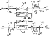
As described below, with the continuous emission mode of time separation emission mode time swap, as described in Figure 4.The emission of Fig. 3 postpones T
1, T
2(32a, 32b) at as shown in Figure 4 four filter 42a-42d, it has the synchronization mistake of this sampler 40a, 40b by emulation.
Vector x
(1)In QPSK symbol and vectorial a
(1)Individual component multiply each other, it is that it is slow and smooth in frequency corresponding to this Rice decline program.x
(2)Assembly is and a
(2)In the decline multiplication.Then filter the vectorial y of gained with four filter 42a-42d
(1)With y
(2), as shown in Figure 4.The individual pulses reaction of these filters is as follows:
h
(1→1)[1]=φ
gg(1T
s+τ
1) (6)
h
(2→1)[1]=φ
gg(1T
s+T
1-T
2+τ
1) (7)
h
(1→2)[1]=φ
gg(1T
s+T
2-T
1+τ
2) (8)
h
(2→2)[1]=φ
gg(1T
s+τ
2) (9)
Consider for following, suppose this propagation delay T in the emission process of an information character
1, T
2Be definite value, yet, in emission process, this synchronization mistake τ
1, τ
2Can change at leisure, thereby τ can take place
1[j], τ
2[j] sequence.
With H
(1 → 1) (z)Filter y
(1)Or with H
(2 → 2) (z)Filter y
(2)Be consider estimation and symbol reality mutually between non-suitable meeting, that is on this first reflector or second reflector, regulate the mistake in the synchronization of sampler 40a, 40b.When this is correctly estimated, that is when presenting best synchronization and τ
1=τ
2=0 o'clock, then the emission function of these filters equaled 1.
Filter H
(2 → 1) (z)With H
(1 → 2) (z)In the representative sample interference of satellite-signal its be in synchronized mode in satellite 1 sampling, vice versa.Mainly be by the poor T of two satellites to the receiving system propagation delay
1-T
2Determine these filters.The output signal of these filters is vectorial y of disturbed specimen
Int (2)With y
Int (1)
So, the output signal representative interference signal of these filters, it is to occur in the actual transmission process, and is estimated by receiving system of the present invention, the method for reseptance that repeats according to the present invention disturbs reduction with the interference signal of estimating.
This is disturbed signal be refitted on " useful signal ", it is to carry out symbolic representation by adder 44a shown in Figure 4,44b.Yet, in the output of adder 44a, 44b, separate in the explanation in the time, use of the output of identical signal in Fig. 3 sampler 40a, 40b; Yet the white noise (white noise) that does not have adder 34a, the added reception antenna of 34b.In brief, suppose noise vector n
(1)With n
(2)The amount of the being changed to σ of onrelevant, and all noise samples each other
2 nN
0/ T
sSo, in output place of adder 34a, 34b, the first received signal amount y
Sync (1)Be the received signal of first reflector that influences of this interference, and the second received signal amount y
Sync (2)It is the received signal that influenced and being synchronized of being interfered to second reflector.
As described below, receiving system of the present invention is shown in Fig. 5 calcspar.This receiving system comprises configuration one reception antenna 50 and any known receiver front end 52, is converted to base band with the RF received signal of changing this antenna 50.The output signal of this antenna front end 52 is transferred into sampler 40, and it comprises the first sampler 40a and the second sampler 40b.About the sample time of the first sampler 40a, be to use synchronization signal 41a control, to reach the sample synchronization to the first reflector 16a shown in Fig. 1.Control second sampler by synchronization signal 41b, to obtain the sampling of synchronization to the second reflector 16b received signal shown in Fig. 1.Yet, in output place of described sampler 40a, there is first received signal, it is the interference that is subjected to second reflector, as shown in Figure 4.In output place of second sampler, there is second received signal, it is the interference that is subjected to first reflector.
Generally speaking, repeat through zero, in output place of the first sampler 40a, first received signal is to be transferred into a code translator 54.In addition, second received signal is the code translator 54 shown in being transferred into, in Fig. 1 emitter line 14a on the first time group the first relevant output 56a place of code element, provide first to receive inferior group.In addition, on the outlet side of the second output line 56b of outlet side, described decoder 54 provides the code element of group for the second time, its be with Fig. 1 emitter line 14b on the second time group code element relevant.Yet, it should be noted that in above-mentioned " zero duplicate paths ", because first and second reflector 16a, the 16b of Fig. 1 are in identical carrier frequencies emission, so on online 56a, the 56b, described reception time group and second receives time group and incomplete code element corresponding to the first emission time group and the second emission time group, but owing to the existence of interference is hindered.
According to the present invention, described first receives time group is transmitted to a calculation element 58 with the second reception time group that hinders that is interfered, receive first interference signal of time group with calculating based on second, and calculate second interference signal based on the inferior group of first reception.Described first interference signal and second interference signal are to be transferred into one to disturb reduction device 60, and respectively at output place of first sampler from deducting from this first received signal, or deduct from second received signal in output place of second sampler, shown in subtracter 60a, 60b among Fig. 1.
One control device 62 is connected to described decoder 54, with the code translator 54 shown in the control, thereby self-interference is reduced device 60 export first received signal output that improves and self-interference and reduce device 60 and export second received signal of improving and decipher, and based on first received signal of improvement and second received signal of improvement, with a plurality of information units under received signal, the output information character.Whether this controller 62 more can further determine one to repeat enough or do not need to continue one or several repetitions.
Further do not repeat if having, if that is meet an end condition that is predetermined fully, the secondary signal of first signal of the improvement that then direct use is deciphered and the improvement of decoding, illustrated as two dotted line arrow 55a, 55b, with a plurality of information unit output information characters.
Yet, if continue another repeating step, then from first received signal of improving and second received signal of improvement, determine one to receive time group, shown in dotted line arrow 55b and 55c, and use first signal of improvement and the secondary signal of improvement, calculate second and receive time group, illustrated as arrow 55e and 55f.
Therefore, once more by calculation element 58, first interference signal that decision improves and second interference signal of improvement, and in disturbing the reduction device, it is respectively to deduct from first received signal or from second received signal, for this repeating step, reduce output place, first signal that decision further improves and the secondary signal of further improving of device in described interference.
If owing to meet the condition that is predetermined fully, so 62 decisions of described controller stop repeating, then use first signal that further improves and the secondary signal of further improving, described information character is by directly decoding and output.Similarly repeat, use first signal that further improves and the secondary signal of further improving, directly calculate described information character for second; Yet based on first signal of the improvement that obtained in first repetition and the secondary signal of improvement, and first signal that further improves is respectively based on first signal of improvement or the secondary signal of improvement with the secondary signal of further improving.
As described below, see also Fig. 6, it is the receiving system among explanation preferred embodiment Fig. 5.Identical element numbers is the identical assembly of expression.In Fig. 6,, do not show sampler 40 compared to Fig. 5.In disturbing the zero duplicate paths that reduces adder 60a, 60b, this first received signal y
Sync (1)Or the second received signal y
Sync (2)Be transferred into this code translator 54, wherein this code translator is shown in the dotted line among Fig. 6.
Implement the receiver of Fig. 6, to receive and the decoding received signal, it is transmitting based on reflector shown in Figure 2.For reaching this purpose, this code translator 54 comprises a de-mapping device 541a, 541b and receives branch in each.Described de-mapping device comprises plural sample value in input side, magnitude of voltage for example, and it is to be converted into de-mapping probability external among de-mapping device 541a, the 541b.The plural sample that symbol y is regulated in representative can be converted into two external de-mapping probability by de-mapping device 541a, and wherein whether to form two code elements of QPSL symbol be 1 or 0 to the explanation of two probability.The meaning of external probability is as described in the following detailed description.Usually, it only is enough to represent probability, and whether code element is 1, and because code element is 1 probability, then whether code element is 0 to this probability.At input side, the vector of plural sample is to be transferred into de-mapping device 541a, and at outlet side, the dual length vector of receiving code unit probability.
Then, in output place of this de-mapping device 541a or 541b, the vector of external adjusting probability is transferred into deinterleaver 542z or 542b, to cancel the displacement of being carried out in this reflector (assembly 20a, the 20b of Fig. 2).In output place of deinterleaver 542a or 542b, Yi Ma probability causes the vector that has equal length in the input of device 542a or 542b in advance.
In a series connection/transducer in parallel,, two continuous assemblies of this vector are divided into groups respectively for the probability (the large 543b of 543a) of coding in advance.In output place of this series connection/transducer 543a in parallel or 543b, in described embodiment, be to use first code element (543a) and second that receives time group to receive the decoding probability in advance of the code element (543b) of time group.
In a preferred embodiment of the present invention, when the calculator rate, first and second receives time group or in these times group, the probability of code element is transferred into the decoder that circles round, it is the SISO decoder, as shown in Figure 6, its operation is according to bcjr algorithm (BCJR=Bahl, Cocke, Jelinek and Raviv), it is to be described in detail in 1974 " to be used for the optimal decoding with the minimized linear code of symbol error speed " at IEEE Information Theory Society (IEEE Transactions onInformation Theory) 284-287 page or leaf.
Provide the decoder implemented to advance the soft decoder that goes out as soft, first of one decoding receives group's code element, it is to be transferred into one parallel connection/serial conversion device 544a, and the code element of the second reception time group of a decoding, it is to be transferred into parallel/series transducer 544b, to form the parallel connection output of SISO decoder serial.It should be noted that the SISO decoder except the BCJR form, that also can use other softly advances the soft decoder that goes out.In addition, it is not important all using soft decoder.On the other hand, also can use the not decoder of calculator rate, but wherein this de-mapping device is to carry out hard 0/1 decision.
Notion of the present invention is particularly suitable for soft decoding, however this preferable de-mapping device be not with sample changeover to code element, but be converted to the probability of code element.In principle, yet whether calculate, be all equalization with code element or with the probability of code element.So if there is not the expression difference, then in the following description, when consulting code element, the probability of code element has identical time reference.
When the processing that disturb to reduce is repetition, represent with Delay Element 545a, 545b that in Fig. 6 it carries out synchronization makes the code element of reception time group of first and second decoding only can be attained at the further processing in next repeating step.By using interleaver 546a, 546b, back coding probability vector with certain repeating step I is provided in an interlace operation once more, with the back coding probability that obtains to reset, it is to be transferred into the designed estimation unit of Fig. 6 estimator respectively, obtain plural sample with the code element that receives time group once more from this first and second, it corresponds respectively to the sample of de-mapping device 541a or 541b input basically.So, represent four symbols of plural number once more in the output signal of this estimator 547a, 547b output place.Therefore, this estimator can be considered " soft " QPSK projection instrument, and the QPSK projection instrument that difference is Fig. 2 in the input actual acquisition position, and this estimator of Fig. 6 547a, 547b obtain a position probability at input side.
The output line of Fig. 6 estimator 547a, 547b is line 56a or the 56b that corresponds respectively to Fig. 5.Compare Fig. 5 and Fig. 6, the decoder described in Fig. 5 comprises the correlation of de-mapping, deinterleaving, SISO decoding, interweave back decoding probability and estimator 547a, 547b.
Impartial is no matter code element first receive the output that there is code translator 54 in time group, as the QPSK symbol of Fig. 6, or when using other adjustment, when regulating symbol, or regulate, as the direct code element of time group when not having to use as other.Clearly, use QPSK to reconcile/separate adjusting though be preferably, personage's adjusting form as can be known of knowing this skill is not that the present invention disturbs the major part that reduces notion.
By this code translator 54, this first and second receive time group code element output can be direct reception time group with two or more separate codes unit, as shown in Figure 6, or the code element of unique reception time group, wherein time group shows with symbol, it depends on two or more code elements of this time group, and wherein the symbol among Fig. 6 is respectively at " soft " QPSK of estimator 547a, 547b output place symbol.
In the preferred embodiment of Fig. 6, calculation element 58 as shown in Figure 5 comprises multiplier 581a, 581b, to finish channel decline that is two branches.In addition, this calculation element comprises time separation (time-discrete) described emission function 582a, 582b, disturbs the interference signal that sees through asynchronization to received signal to consider internal symbol.In disturbing the reduction device, wherein this first interference signal is the adder 60a that is transferred on the line 583a, and second interference signal is the second adder 60a that is transferred on the line 583b, and in code translator 54, first and second received signal that produces improvement is in incoming line 61a or 61b.
In a preferred embodiment of the present invention, as shown in Figure 6, this de-mapping device 541a or de-mapping device 541b are implemented as special de-mapping device, and it is to use call information to carry out the de-mapping function.Also can provide call information, and be meant the external decoding probability p among Fig. 6 from the SISO decoder
C, extrdec[i]
With the known way of prior art, determine the external decoding probability of first branch (1) and second branch (2) from back decoding probability.For the code element of first and second time group, from back decoding probability, the decision of this outside decoding probability is known in this skill.About this point, see also 1996 (IEEE Transactions on Information Theory) 429-437 page or leaf JoachimHagenauer, Elke Offer of IEEE Information Theory Society and Lutz Papke " two block of bytes and convolution code repeat decoding ".
Outside decoding probability is to be transferred into the first parallel/series transducer 550a in this first branch or be transferred into the second parallel/series transducer 550b in second branch, and as mentioned above, postponing this delay 545a, 545b by deferred mount 551a or 551b, is a dup loop to represent this.In this external decoding probability of interleaver 552a displacement, that is according to identical specification, it is also respectively at carrying out among interleaver 546a or the 546b or carrying out in interleaver shown in Figure 2.The external decoding probability of being replaced, as shown in Figure 6, be meant the probability of videoing in advance, it is to be transferred into this de-mapping device 541a, 541b as call information, to improve the de-mapping device of de-mapping function, reach preferable bit-errors speed in output place of this decoder at last compared to no call information.
When controller 62 had determined to repeat end condition and satisfied fully, its may command SISO decoder 540 then was to export back decoding probability in the individual information unit of output place.Then described back decoding probability is transferred into threshold value decision unit 555, to obtain the information character of decoding
, it is transferred into an information track 62 at last.
As described below, the function of preferable code translator shown in Fig. 6, it is described in detail as follows.
By aforesaid equation (4) and (5), as can be known when this sampler 40 synchronization on satellite 1 (41a), and the very strong jamming of this satellite 2 takes place, vice versa.Especially, when producing this interference signal, this pulse reaction h
(2 → 1)[1] and h
(1 → 2)[1] can be very long.According to the present invention, this interference signal estimated, and is incorporated into corresponding received signal, disturbs and reduces to obtain one by device 60.Complexity that it should be noted that the technology of the present invention mainly is to be independent of to disturb outside the pulse reaction length that produces signal.
As mentioned above, the decoder 540 of implementing Fig. 6 as softly advance/softly go out channel decoder (SISO decoder), it is preferably and uses this bcjr algorithm, to obtain the soft estimation of so-called this interference signal.On the other hand, can use any other decoder that circles round, this first and second received signal of its decodable code, to obtain the code element of the first reception time group, it is relevant with the code element of the first emission time group, and the code element of the second reception time group, it is relevant with the code element of the second emission time group.Be preferably, use any SISO decoder, certainly this first and second receive the decoding probability in advance of time group, provide decoding probability in back to receive time group in this first and second.
Especially, in the repeating step i that this receiver repeats, use the output of decoder of (I-1) individual repetition of this interferences reduction.About the expression mode of this application case, last pointer that it should be noted that the variable that is used for receiver is that representative repeats, and wherein this variable is calculated.Suppose in repeating i-1 the back decoding probability that this channel decoder calculates, wherein p
C, postdec[k][i-1] illustrates the transmitter code position c[k of institute] equal 1 probability.Therefore, general unrestricted under, it is logical one that the probability of an incident is considered to individual bits.
This SISO further calculates relevant external probability p
C, postdec[k][i-1] is in the position of this character c.In an identical manner, this back decoding probability and external probability all are divided into stream and time group in this decoder, and are changed by parallel/series, thereby the code character c that can obtain respectively in satellite 1 or 2
(1)With c
(2)The vectorial p of the back decoding probability of meta
C (1), postdec[i] and p
C (2), postdec[i].The external probability that can obtain to be correlated with equally is therefore for having external probability result's corresponding vector.Corresponding interleaver in Fig. 6 is replaced two vectors.
Use
With
 The expression mode as external probability, it is calculated by decoder, is used as de-mapping probability in advance.Can use by the back decoding probability of permutation code position, to rebuild the vector x of the QPSK symbol of being launched
(1)With x
(2)
The expression mode as external probability, it is calculated by decoder, is used as de-mapping probability in advance.Can use by the back decoding probability of permutation code position, to rebuild the vector x of the QPSK symbol of being launched
(1)With x
(2)
As the decoder code sign c of all emissions of identification reliably
kThe time, use this vector x
(1)With x
(2) With
Wherein to consider the reliability of decoder output.For the misjudgment with MMSE (MMSE=minimum average B configuration square mistake) minimizes, described soft estimate is calculated as follows:
Herein,
 Be the desired value of representing x (1), and vector
The sign indicating number position that the probability support that comprises is replaced:
fork=0,...,N/2-1。
These the soft estimations that can use estimator 547a or 547b to be calculated respectively for synchronized signal on two satellites, reduce from sample y
Sync (1)With y
Sync (2)The interference of vector.For reaching this purpose, at first by inciting somebody to action
 Or
Or
 Multiply by the decline coefficient of estimation
 Or
Or
 , rebuild all interference signals.Then respectively with
With
, rebuild all interference signals.Then respectively with
With
 Filter the result who is obtained
 With
With
 For filter H
(1 → 2)(z) and H
(2 → 1)(z), these filters are represented the estimation of receiver, and it is that the interference that the time shown in Figure 4 separates in the emission mode is responsible for.So these filters have following pulse reaction:
For filter H
(1 → 2)(z) and H
(2 → 1)(z), these filters are represented the estimation of receiver, and it is that the interference that the time shown in Figure 4 separates in the emission mode is responsible for.So these filters have following pulse reaction:
When the pulse reaction g (t) of this emission filter is real number value, below set up: φ
Gg(-t)=φ
Gg(t).And following establishment:
And it is corresponding
The output signal of two filters
 With
With
 That is interference signal y
Int (1)With y
Int (2)Estimation, can be from this received signal y
Sync (1)With y
Sync (2)Deduct, it is to be synchronized in two satellites.
That is interference signal y
Int (1)With y
Int (2)Estimation, can be from this received signal y
Sync (1)With y
Sync (2)Deduct, it is to be synchronized in two satellites.
If the estimation of disturbing is perfectly, then the gained vector
With
Do not have interference.In this example, have perfect synchronization or symbol time and reply, that is τ
1=τ
2=0, then j is to sample
 The whole relative energy E of information carrier part
s[j] can be defined as follows:
The whole relative energy E of information carrier part
s[j] can be defined as follows:
Herein, σ
x 2Variable for QPSK arrangement in the reflector.
Yet, if consider this decoder variation of output signals reliability, at vector
 In still have remaining interference.As Ralf R.Muller in 1998 and Johannes B.Huber in wideband wireless telecommunications 110-115 page or leaf " cancellation is disturbed in the soft decision that repeats of CDMA ".
 Sample
 In, the variation (σ of residual interference
Int (1)[j] [i])
2As follows:
In, the variation (σ of residual interference
Int (1)[j] [i])
2As follows:
Herein, filter H
(2 → 1)(z) rough length is 2L+1.The attention of value be when with indivedual estimations
 Displacement a
(2)[j] and h
(2 → 1)(1) time, receiver (σ
Int (1)[j] [i])
2Can estimate.
Displacement a
(2)[j] and h
(2 → 1)(1) time, receiver (σ
Int (1)[j] [i])
2Can estimate.
As described below, de-mapping device 541a or the 541b of Fig. 6 are further described.There is sample
 In average free distortion (distortion) d
(1)Whole power of [j] [i] are residual interference power (σ
Int (1)[j] [i])
2With noise power σ
n 2Totalling.Complex random variable
In average free distortion (distortion) d
(1)Whole power of [j] [i] are residual interference power (σ
Int (1)[j] [i])
2With noise power σ
n 2Totalling.Complex random variable
And it is acyclic.See also person described in the 42nd 3473-3482 page or leaf " circulation " of I EEE Signal Processing Society in 1994.In fact equally has non-Gaussian Profile.In brief, d
(1)[j] [i] is simulated as two-dimentional real number Gaussian random variable d in the receiver
(1)[j] [i], that is its performance is as d
(1)[j] [i].Optimum solution projection instrument with call information is to be assumed to be the basis with this.
TSymbology one bit manipulation device.So, probability density function (pdf) f
d (1) [j] [i](d
(1)[j] [i]) as follows:
Two assembly d
I (1)[j] [i] and d
Q (1)Variable (the σ of [j] [i]
d (1) , 1[j] [i])
2With (σ
d (1) , Q[j] [i])
2, and co-variation amount (σ wherein
d (1) , IQ[j] [i])
2Be calculated as follows:


Herein
 With
Be real part and the imaginary part of representative to dependent variable.For asking simple expression mode, by width of cloth numerical value QPSK symbol
With
Be real part and the imaginary part of representative to dependent variable.For asking simple expression mode, by width of cloth numerical value QPSK symbol
 Middle code character
In a pair of
The position illustrates the reflection in the reflector continuously.By sample
Middle code character
In a pair of
The position illustrates the reflection in the reflector continuously.By sample
 Middle distortion (distortion) d
(1)The probability density function PDF of the above-mentioned expression of [j] [i], and use de-mapping probability in advance
Middle distortion (distortion) d
(1)The probability density function PDF of the above-mentioned expression of [j] [i], and use de-mapping probability in advance
 The probability additional calls information of being given, its amount is defined as follows, and it is that it is right corresponding to the sign indicating number position corresponding to the connection pdf of this QPSK signaling point of emission
 And reception sample


This moment is for receiver (that is the τ of perfect synchronizationization
1=0), the back de-mapping probability calculated of optimum solution projection instrument is as follows:
In identical mode, this de-mapping device is as follows with the back de-mapping probability that the odd number pointer calculates the sign indicating number position:
To repeat receiver, being preferably the probability that exchanges between the receiver assembly that participates in is external probability.Therefore, this de-mapping device calculates following external probability, and it is delivered to this decoder:
As mentioned above, in projection instrument 22a, the 22b of Fig. 2, use the Gray reflection.This one yard position of expression is right
Decision QPSK symbol x
(1)The I assembly of [j], and other yard position decision Q assembly.Therefore this Gray reflection is corresponding to the coding of certain kind, and it is meant the system coding in the coding theory, and this yard position can be directly with the QPSK coded identification.By coding theory, the output signal of the decoder of further known BCJR form, it is relevant with systematic encoder, compared to the input to this decoder, on average has the reliability of improvement, is independent of outside signal and the noise proportional (SNR).So this system coding has special advantage for low signal/noise ratio, and be preferably and be used for iteration scheme, it is with low signal/noise proportional operation.
Though in the example of Fray reflection, it is illogical that the first meeting meeting feels to repeat between decoder and QPSK de-mapping device, its advantage is as described below.General interference reduction can cause sample
 In acyclic distortion (distortion) d
(1)[j] [i], that is equation 17 to
In acyclic distortion (distortion) d
(1)[j] [i], that is equation 17 to
Set up.So, depend on I assembly and the Q assembly statistics
 Even use the Gray reflection and
 I and the Q assembly in information in fact right corresponding to this
 Bit code, because statistical dependence, the probability of de-mapping in advance of this single position still influences other back de-mapping probability.
For example, can use following Gray reflection:
X(0,0)=-1-j,X(0,1)=1-j,X(1,0)=-1+jandX(1,1)=1+j
The position
 Be to be mapped across the Q assembly.Moreover, suppose:
unda
(1)[j]=1。
Fig. 7 is explanation
Calculating, that is distortion d (1) [j] [i] circulates.For the distortion of this kind form,
 Be to rely on
The Q assembly.This amount is the probability of reflection in advance that is independent of sign indicating number position among the assembly I
Be to rely on
The Q assembly.This amount is the probability of reflection in advance that is independent of sign indicating number position among the assembly I
 Outside.
When considering following situation,
Then as described in Figure 8, by the probability density function that receives sample
 This distortion is obviously acyclic.
At this moment, external probability
The function that is had as shown in Figure 9, and in this Q assembly the external probability of sign indicating number position be depend on Q and
 The I assembly.
In addition, be the probability of de-mapping in advance that depends on this yard position in the I assembly equally
 For this point is described, the probability of the de-mapping in advance hypothesis of I assembly is as follows:
Figure 10 is the explanation probability density function
And Figure 11 is explanation
 The complete asymmetry of the function of the external probability of Q assembly, and be different from person shown in Fig. 7, this is because the difference of I assembly de-mapping probability in advance.
The carrying out of the second satellite de-mapping mainly is the de-mapping as first satellite.The external probability vector that is calculated by soft de-mapping device
 With
, as shown in Figure 6, carry out deinterleaving by the interleaver of correspondence, wherein this de-mapping device be with this reflector in corresponding interleaver opposite.
With
, as shown in Figure 6, carry out deinterleaving by the interleaver of correspondence, wherein this de-mapping device be with this reflector in corresponding interleaver opposite.
The preparation of at least one interleaver and be preferably an other interleaver and launch branch in an emission branch has three major advantages in each, and this is that the present invention is preferably the reason of using interleaver.
1. the channel of emission system is weak channel.So, also weak deeply as is known, need open strong weak generation with individual symbols by different position in the code character.
2. this de-mapping device and the external probability of decoder repeated exchanged.Contiguous probability is that upward tool is dependent for statistics in the corresponding output vector of one assembly.Yet, on the other hand, suppose that contiguous probability is that statistics goes up the tool dependence in the input of an assembly.When meeting the statistics dependence of this incoming symbol fully,, reach the effect an of the best for each duplicated system.So, be preferably and use an interleaver, with distribution adjacent assemblies in the output section of assembly to the diverse location or the assembly of other assembly input.This kind processing typically refers to external probability and " separates relevance ".
Since the interference in the notion of the present invention reduce,
 With
With
 In distortion be affected really.For example, if this interference has a mistake and distortion very high in reducing, then be not that the QPSK symbol is subjected to serious interference, several continuous QPSK symbols also are subjected to serious interference.As in the channel that fails, these wrong quick-fried diverse locations that also need to be assigned in the code character that dash.
As interleaver, be preferably other above-mentioned s-random interleaver.Because its expansion restriction, it guarantees that contiguous assembly is brought to the long-range output precision of its input really, therefore gets rid of dark decline and wrong quick-fried dashing.On the other hand, one at random, that is in the duplicated system performance of non-general interleaver is better than general structure.
This time code character c
(1)With c
(2)Decipher the deinterleaving vector of probability in advance
 With
With
 Changed by parallel/series at last, and as inputing to the SISO decoder.Decipher probability p in advance based on these
C, predec[i] can calculate back decoding probability p
C, postdec[i] and external probability p
C, extrdec[i].
Changed by parallel/series at last, and as inputing to the SISO decoder.Decipher probability p in advance based on these
C, predec[i] can calculate back decoding probability p
C, postdec[i] and external probability p
C, extrdec[i].
At this moment, finish the repetition i of this receiver.Compared to p
C, postdec[i-1] and p
C, extrdec[i-1] works as p
C, postdec[i] and p
C, extrdec[i] when better reliability degree was provided, these vectors can be used for other and repeat i+1, reduced further to improve to disturb.When this duplicated system correctly restrains, then after repeating for several times, this vector
 With
Noiseless.The probability of the given back decoding of this decoder then p
C, postdec[i] in the threshold value separator 555 of information bit u to Fig. 6, it provides the vector of estimated information position
With
Noiseless.The probability of the given back decoding of this decoder then p
C, postdec[i] in the threshold value separator 555 of information bit u to Fig. 6, it provides the vector of estimated information position
 To
To information track 62.
When this decoder non-output signal leaves first emission, that is after first repeats, be preferably average probability p
C, postdec[0]=p
C, extrdec[0]=[1/21/2...1/2] as the output valve of this repetition.These probability be expression each yard position ck can be 0 and identical probability 1/2 as 1.Therefore, estimated interference is
So, in first repeats, can reach noiseless reduction.By setting p
C, extrdec[0]=[1/21/2...1/2], the present invention is soft separates the effect of penetrating device 541a, 541b firmly and is equal to known QPSK de-mapping device.Known QPSK de-mapping device effect do not have de-mapping probability in advance given call information.So it is to repeat corresponding to first of simple receiver that first of receiver repeats, and noiseless cancellation and have known QPSK de-mapping device.
For example, can use information character with 494 information unit length.Is 1/4 with sign indicating number memory nu=6 with sign indicating number speed Rc, generated code character length N=1000 and length
。The code element of a group also comprises 1000 code elements.So the bulk velocity of this system is R=494: 500=0.99.Two interleavers of the length N/2=1000 that uses can be used as different s-random interleavers, the expanding value s=17 that it had.The emission filter G (f) of this system can be used as square root cosine filter, and it has attenuating parameter alpha=0.2.
For the emulation or the estimation of send channel, simulated channel becomes Rice decline, that is it comprises LOS assembly (LOS=sight line) and Rayleigh decline assembly, and it has a pair of dependent variable.For emulation, the maximum Doppler frequency of the normalization of these programs can be assumed to be 0.01.Add up independently Rice decline program for two, can represent corresponding Rice parameter.
Represented emulation, after some (usually surpass 5) repeating steps, without any essence improve.So, after five times are repeated, can reach a convergence.
It should be noted that synchronization, can use different known concept for sampler, training sequence for example, it is to transmit from two different reflectors, but and wherein the sampler synchronization to corresponding reflector.In this synchronization process, in order to suppress to disturb, for example in the known time window that is predetermined of receiver, always only there is a reflector to launch, therefore can reach and have the low optimal synchronisationization of disturbing.In order to calculate interference signal, wherein be to use channel coefficients, to finish the weighting among multiplier 581a, the 581b, can use known channel estimation methods, it is the operation training sequence also.In addition, blindly method of estimation existence is also arranged, it can reach a channel estimating and not have the training sequence of knowing in advance.
Fig. 6 launches filter 582a, 582b and also sets up, the non-real number synchronization of its this sampler of emulation.As first approximation, when hypothesis one real number synchronization, the emission function of these filters can be set to " 1 ".Look closely in this case, this emission function also can be estimated according to experience.
Claims (10)
1. receiving system that is used to receive a replacement received signal, one first and 1 second replacement that transmits that described replacement received signal is launched corresponding to one first reflector (16a) and one second reflector (16b), described second reflector is be disposed at described first reflector (16a) long-range, it is in identical frequency band that wherein said first and second transmits, wherein be to use the code element of one first emission time group and produce described first and transmit, wherein be to use the code element of one second emission time group and produce described second and transmit, the a plurality of code elements of the common representative of the code element of the code element of the wherein said first emission time group and the described second emission time group, it is the information character with a plurality of information units, produce by a redundant addition coding, described receiving system comprises:
The device (40) of described replacement received signal is used to take a sample, it is synchronized with described first reflector, to obtain and the first one first relevant received signal that transmits of being launched, and described device (40) is to be used for and the take a sample received signal of described replacement of described second transmitter synchronization, to obtain and the second one second relevant received signal that transmits of being launched;
One code translator (54), be used to decipher described first and second received signal, to obtain the code element of one first reception time group, it is relevant with the code element of the described first emission time group, and decipher described first and second received signal, to obtain the code element of one second reception time group, it is relevant with the code element of the described second emission time group;
One calculation element (58) in order to by using described second code element that receives time group to calculate one first interference signal, and uses described first to receive the code element of time group and calculate one second interference signal;
One disturbs reduction device (60), be used in conjunction with described first interference signal and described first received signal, and be used in conjunction with described second interference signal and described second received signal, to obtain first received signal of improving and second received signal of improving; And
One control device, be used to control described code translator (54), therefore first received signal of described improvement and second received signal of described improvement have similarly been deciphered, and based on first received signal of described improvement and second received signal of described improvement, output device has the described information character of described a plurality of information units.
2. receiving system as claimed in claim 1, it is characterized in that implementing described control device (62) and reduce device (60) and described calculation element (58) to control described interference, therefore calculate first and second received signal of another improvement equally, its be by one or for several times repeating step use first received signal of described improvement and second received signal of described improvement to calculate, and in order to control described code translator (54), to obtain to have the described information character of a plurality of information units, it is to use first received signal of described another improvement and second received signal of described another improvement to carry out.
3. receiving system as claimed in claim 1 or 2 is characterized in that described code translator (54) comprises:
One mapping device (541a, 541b) is used for described first received signal or described second received signal are converted to the decoding probability in advance that described first code element and second that receives time group receives the code element of time group;
One softly advances the soft decoder (540) that goes out, and is used to calculate described first and second and receives a back decoding probability of the code element of time group; And
One estimation unit (547a, 547b) is used for receiving the described back decoding probability of the code element of time group based on described first and second, estimates that described first and second receives time group.
4. receiving system as claimed in claim 3 is characterized in that describedly softly advancing that soft to go out decoder be a BCJR decoder.
5. receiving system as claimed in claim 3 is characterized in that when producing described first and second and transmit, and have the function that interweaves, and wherein said code translator (54) comprises also:
One deinterleaver (542a, 542b) is used to cancel the described described function that interweaves that first and second transmits, and wherein said deinterleaver is to be connected between described mapping device (541a, 541b) and the described decoder (540); And
One interleaver (546a, 546b), to show the identical function that interweaves, wherein said interleaver is to be configured between described decoder (540) and the described estimation unit (547a, 547b).
6. receiving system as claimed in claim 3 is characterized in that implementing described mapping device (541a, 541b), manipulating the page information of handling repeating step from one, and
Wherein said page information is the external probability that is obtained from described back decoding probability.
7. receiving system as claimed in claim 6, it is characterized in that implementing described sampler (40) so that use a training sequence that is predetermined from described first reflector (16a), and from a training sequence that is predetermined of described second reflector (16b) and synchronization.
8. receiving system as claimed in claim 3 is characterized in that described calculation element (58) more comprises:
One first device (581a), be used for being obtained from described second characteristic of channel weighting to described second code element or that receives time group that receives the code element of time group and regulate symbol, to obtain the adjusting symbol that second of a weighting receives a time group or a weighting one;
One second device (581b), be used for being obtained from described first characteristic of channel weighting to described first code element or that receives time group that receives the code element of time group and regulate symbol, to obtain the adjusting symbol that first of a weighting receives a time group or a weighting one.
9. receiving system as claimed in claim 3 is characterized in that described de-mapping device is that the de-mapping device is keyed in four phase phase shifts, and
Wherein said estimation unit is a minimum average B configuration variance estimation unit.
10. method that is used to receive a replacement received signal, described replacement received signal is corresponding to first and second replacement that transmits of being launched by one first reflector (16a) and one second reflector (16b) respectively, described second reflector is be disposed at described first reflector (16a) long-range, it is in identical frequency band that wherein said first and second transmits, wherein be to use the code element of one first emission time group and produce described first and transmit, wherein be to use the code element of one second emission time group and produce described second and transmit, the a plurality of code elements of the common representative of the code element of the code element of the wherein said first emission time group and the described second emission time group, it is the information character with a plurality of information units, produce by a redundant addition coding, described method comprises:
Be synchronized with the described shared received signal of described first reflector (16a) sampling, to obtain and the first one first relevant received signal that transmits of being launched;
Be synchronized with the described shared received signal of described second reflector (16b) sampling, to obtain and the second one second relevant received signal that transmits of being launched;
Decipher described first and second received signal, to obtain the code element of one first reception time group, it is relevant with the code element of the described first emission time group;
Decipher described first and second received signal, to obtain the code element of one second reception time group, it is relevant with the code element of the described second emission time group;
Calculate one first interference signal, it is to use described second to receive the code element of time group, and calculates one second interference signal, and it is to use the code element of the described first reception time group;
In conjunction with described first interference signal and described first received signal, and,, disturb reduction to obtain one to obtain first received signal of improving and second received signal of improving in conjunction with described second interference signal and described second received signal; And
Decipher first received signal of described improvement and second received signal of described improvement, and, export the described information character of described a plurality of information units based on first received signal of described improvement and second received signal of described improvement.
Applications Claiming Priority (2)
| Application Number | Priority Date | Filing Date | Title |
|---|---|---|---|
| DE10220892.1 | 2002-05-10 | ||
| DE10220892A DE10220892A1 (en) | 2002-05-10 | 2002-05-10 | Sending device and receiving device |
Publications (2)
| Publication Number | Publication Date |
|---|---|
| CN1653740A CN1653740A (en) | 2005-08-10 |
| CN100382475C true CN100382475C (en) | 2008-04-16 |
Family
ID=29413734
Family Applications (1)
| Application Number | Title | Priority Date | Filing Date |
|---|---|---|---|
| CNB038105551A Expired - Fee Related CN100382475C (en) | 2002-05-10 | 2003-05-06 | Transmitting device and receiving device |
Country Status (8)
| Country | Link |
|---|---|
| US (1) | US7372802B2 (en) |
| EP (1) | EP1504557B1 (en) |
| JP (1) | JP4098773B2 (en) |
| CN (1) | CN100382475C (en) |
| AT (1) | ATE314761T1 (en) |
| AU (1) | AU2003222317A1 (en) |
| DE (2) | DE10220892A1 (en) |
| WO (1) | WO2003096599A1 (en) |
Families Citing this family (22)
| Publication number | Priority date | Publication date | Assignee | Title |
|---|---|---|---|---|
| EP2690814A1 (en) * | 2003-11-21 | 2014-01-29 | Panasonic Corporation | Multi-antenna apparatus using different interleaving patterns |
| CN1998176B (en) * | 2004-07-01 | 2011-06-15 | 高通股份有限公司 | Advanced MIMO interleaving method and system |
| DE102004032222B4 (en) | 2004-07-02 | 2011-02-10 | Infineon Technologies Ag | Receiver of a positioning system with improved sensitivity and positioning method |
| US7593489B2 (en) * | 2005-03-14 | 2009-09-22 | Koshy John C | Iterative STBICM MIMO receiver using group-wise demapping |
| EP1746756B1 (en) * | 2005-07-21 | 2013-01-16 | STMicroelectronics Srl | A method and system for decoding signals, corresponding receiver and computer program product |
| US7636397B2 (en) * | 2005-09-07 | 2009-12-22 | Mclaughlin Michael | Method and apparatus for transmitting and receiving convolutionally coded data for use with combined binary phase shift keying (BPSK) modulation and pulse position modulation (PPM) |
| FR2937480B1 (en) * | 2008-10-22 | 2011-05-06 | Commissariat Energie Atomique | TURBOCODEUR DISPENSES FOR BLOCKED CHANNEL CHANNELS |
| US8448033B2 (en) * | 2010-01-14 | 2013-05-21 | Mediatek Inc. | Interleaving/de-interleaving method, soft-in/soft-out decoding method and error correction code encoder and decoder utilizing the same |
| US8744026B2 (en) * | 2010-10-13 | 2014-06-03 | Telefonakktiebolaget Lm Ericsson (Publ) | Method and apparatus for interference suppression using a reduced-complexity joint detection |
| JP5578617B2 (en) | 2010-10-18 | 2014-08-27 | パナソニック インテレクチュアル プロパティ コーポレーション オブ アメリカ | Transmission method, transmission device, reception method, and reception device |
| US8724715B2 (en) | 2011-02-17 | 2014-05-13 | Massachusetts Institute Of Technology | Rateless and rated coding using spinal codes |
| US9160399B2 (en) | 2012-05-24 | 2015-10-13 | Massachusetts Institute Of Technology | System and apparatus for decoding tree-based messages |
| US9219631B2 (en) * | 2012-09-21 | 2015-12-22 | Kratos Integral Holdings, Llc | System and method for increasing spot beam satellite bandwidth |
| EP2920892A4 (en) * | 2012-11-15 | 2016-07-20 | Novelsat Ltd | Echo cancellation in communication transceivers |
| US9270412B2 (en) * | 2013-06-26 | 2016-02-23 | Massachusetts Institute Of Technology | Permute codes, iterative ensembles, graphical hash codes, and puncturing optimization |
| US9967021B2 (en) | 2016-07-14 | 2018-05-08 | Suntrust Bank | Systems and methods for signal cancellation in satellite communication |
| CN108206798B (en) * | 2016-12-20 | 2020-07-28 | 北京大学 | Communication method for inhibiting interference of adjacent transmitters |
| FR3063856B1 (en) * | 2017-03-09 | 2019-04-26 | Commissariat A L'energie Atomique Et Aux Energies Alternatives | EMISSION / RECEPTION SYSTEM USING ORTHOGONAL-LINEAR JOINT MODULATION |
| US10200071B1 (en) * | 2017-08-07 | 2019-02-05 | Kratos Integral Holdings, Llc | System and method for interference reduction in radio communications |
| DE102018202648B4 (en) | 2018-02-21 | 2019-10-17 | Innovationszentrum für Telekommunikationstechnik GmbH IZT | A receiver and method for receiving a combination signal using probability density functions |
| DE102019209801A1 (en) * | 2019-07-03 | 2021-01-07 | Innovationszentrum für Telekommunikationstechnik GmbH IZT | Receiver for receiving a combination signal with consideration of inter-symbol interference and low complexity, method for receiving a combination signal and computer program |
| DE102019209800B4 (en) * | 2019-07-03 | 2021-07-29 | Innovationszentrum für Telekommunikationstechnik GmbH IZT | Receiver for receiving a combination signal taking into account inter-symbol interference, method for receiving a combination signal and computer program |
Citations (1)
| Publication number | Priority date | Publication date | Assignee | Title |
|---|---|---|---|---|
| CN1327635A (en) * | 1999-10-29 | 2001-12-19 | 三菱电机株式会社 | Communication device and communication method |
Family Cites Families (13)
| Publication number | Priority date | Publication date | Assignee | Title |
|---|---|---|---|---|
| US5341395A (en) * | 1992-11-24 | 1994-08-23 | At&T Bell Laboratories | Data recovery technique for asynchronous CDMA systems |
| DE19647833B4 (en) * | 1996-11-19 | 2005-07-07 | Deutsches Zentrum für Luft- und Raumfahrt e.V. | Method for simultaneous radio transmission of digital data between a plurality of subscriber stations and a base station |
| US5991273A (en) * | 1997-05-01 | 1999-11-23 | Nortel Networks Corporation | Determining SINR in a communications system |
| US5887035A (en) * | 1997-10-31 | 1999-03-23 | Ericsson, Inc. | Method for joint equalization and detection of multiple user signals |
| US6304618B1 (en) * | 1998-08-31 | 2001-10-16 | Ericsson Inc. | Methods and systems for reducing co-channel interference using multiple timings for a received signal |
| US20020110206A1 (en) * | 1998-11-12 | 2002-08-15 | Neal Becker | Combined interference cancellation with FEC decoding for high spectral efficiency satellite communications |
| JP3464981B2 (en) | 1998-12-03 | 2003-11-10 | フラウンホーファー−ゲゼルシャフト・ツール・フェルデルング・デル・アンゲヴァンテン・フォルシュング・アインゲトラーゲネル・フェライン | Information transmitting apparatus and method, and information receiving apparatus and method |
| US6574235B1 (en) | 1999-08-12 | 2003-06-03 | Ericsson Inc. | Methods of receiving co-channel signals by channel separation and successive cancellation and related receivers |
| US6847688B1 (en) * | 2000-10-30 | 2005-01-25 | Ericsson Inc. | Automatic frequency control systems and methods for joint demodulation |
| FR2821217B1 (en) * | 2001-02-21 | 2003-04-25 | France Telecom | METHOD AND SYSTEM FOR ITERATIVE CODING-DECODING OF DIGITAL DATA STREAMS ENCODED BY SPATIO-TEMPORAL COMBINATIONS, IN MULTIPLE TRANSMISSION AND RECEPTION |
| US6691263B2 (en) * | 2001-05-03 | 2004-02-10 | Agere Systems Inc. | Interative decoding based on dominant error events |
| US20030161258A1 (en) * | 2002-02-22 | 2003-08-28 | Jianzhong Zhang | Apparatus, and associated method, for a multiple-input, multiple-output communications system |
| US7254192B2 (en) * | 2002-07-12 | 2007-08-07 | Texas Instruments Incorporated | Iterative detection in MIMO systems |
-
2002
- 2002-05-10 DE DE10220892A patent/DE10220892A1/en not_active Withdrawn
-
2003
- 2003-05-06 AT AT03717328T patent/ATE314761T1/en active
- 2003-05-06 AU AU2003222317A patent/AU2003222317A1/en not_active Abandoned
- 2003-05-06 JP JP2004504441A patent/JP4098773B2/en not_active Expired - Fee Related
- 2003-05-06 CN CNB038105551A patent/CN100382475C/en not_active Expired - Fee Related
- 2003-05-06 WO PCT/EP2003/004759 patent/WO2003096599A1/en active IP Right Grant
- 2003-05-06 DE DE50302072T patent/DE50302072D1/en not_active Expired - Lifetime
- 2003-05-06 EP EP03717328A patent/EP1504557B1/en not_active Expired - Lifetime
-
2004
- 2004-11-10 US US10/985,566 patent/US7372802B2/en not_active Expired - Fee Related
Patent Citations (1)
| Publication number | Priority date | Publication date | Assignee | Title |
|---|---|---|---|---|
| CN1327635A (en) * | 1999-10-29 | 2001-12-19 | 三菱电机株式会社 | Communication device and communication method |
Non-Patent Citations (4)
| Title |
|---|
| Fading Correlation and its Effect on the CapacityofSpace-Time Turbo Coded DS/CDMA Systems. D.J van Wyk, L.P.Linde.Milcom 1999 IEEE Military Communications Conference Proceedings,Vol.1 . 1999 * |
| Iterative Interference CancellationSchemewithPilot-AidedSpace-Time Estimation in DS-CDMASystems. Loic Brunel , David Mottier.VTC Fall 2001 IEEE 54th vehicular technology conference proceedings,Vol.1 . 2001 * |
| Multiuser Detector with Transmit Diversity intheConvolutionally Coded DS/CDMA Systems. Wang Yong, Wang Haifeng, Yu Xiao-Hu, Cheng ShiXin.VTC 2000-spring 2000 IEEE 51st Vehicular Technology Conference Proceedings,Vol.1 . 2000 * |
| Space-Time Turbo Codes with Full Antenna Diversity. Hsuan-Jung Su, Evaggelos Geraniotis.IEEE Transactions on communications,Vol.49 No.1. 2001 * |
Also Published As
| Publication number | Publication date |
|---|---|
| DE50302072D1 (en) | 2006-02-02 |
| JP2005531944A (en) | 2005-10-20 |
| DE10220892A1 (en) | 2003-12-18 |
| AU2003222317A1 (en) | 2003-11-11 |
| ATE314761T1 (en) | 2006-01-15 |
| US7372802B2 (en) | 2008-05-13 |
| WO2003096599A1 (en) | 2003-11-20 |
| CN1653740A (en) | 2005-08-10 |
| US20050111347A1 (en) | 2005-05-26 |
| EP1504557A1 (en) | 2005-02-09 |
| EP1504557B1 (en) | 2005-12-28 |
| JP4098773B2 (en) | 2008-06-11 |
Similar Documents
| Publication | Publication Date | Title |
|---|---|---|
| CN100382475C (en) | Transmitting device and receiving device | |
| CN101981932B (en) | Apparatus and method for decoding signals | |
| CN1213547C (en) | Multipath cdma receiver for reduced pilot | |
| EP2421213B1 (en) | Phase pulse system and method for bandwidth and energy efficient continuous phase modulation | |
| CN1463525B (en) | Apparatus and method for decision feedback sequence estimation for reduction of error propagation in decision feedback equalizer | |
| US6215762B1 (en) | Communication system and method with orthogonal block encoding | |
| CN100583975C (en) | Dual stream structure digital television transmission and receiving method using hybrid of E-8VSB, E-4VSB and P-2VSB | |
| US7620881B2 (en) | System and method for communicating data using iterative equalizing and decoding and recursive inner code | |
| EP1821481B1 (en) | OFDM - MIMO radio frequency transmission system | |
| DE102010060520A1 (en) | Device and method for störrobusten decoding | |
| CN1430818A (en) | CDMA system which uses pre-rotation before transmission | |
| KR100849338B1 (en) | Apparatus and method for coding/decoding of sttd in ofdm mobile communication system | |
| CN100571419C (en) | The method for transmitting and receiving of a kind of coding modulation and demodulation system and signal thereof | |
| EP1897260A1 (en) | Method and apparatus for spatial temporal turbo channel coding/decoding in wireless network | |
| CN101861734B (en) | Code enhanched staggercasting | |
| Jayaweera et al. | A RAKE-based iterative receiver for space-time block-coded multipath CDMA | |
| Farrell et al. | Soft-decision error control for HF data transmission | |
| CN102065044B (en) | Method and system for tracking phase in a receiver for 8VSB | |
| WO2002041550A1 (en) | Non-linear code-division multiple access technology with improved detection algorithms and error correction coding | |
| Park et al. | Design criteria and performance of space-frequency bit-interleaved coded modulations in frequency-selective Rayleigh fading channels | |
| Stefanov | Space-time turbo coding for high spectral efficiency wireless communications | |
| EP2566119A1 (en) | Generalized rotated constellations for time-frequency slicing | |
| Chen | Iterative Detection for Overloaded Multiuser MIMO OFDM Systems | |
| Tang | Coding and interference suppression for CDMA systems on fading channels | |
| Wong et al. | Nonredundant error correction DQPSK for the aeronautical-satellite channel |
Legal Events
| Date | Code | Title | Description |
|---|---|---|---|
| C06 | Publication | ||
| PB01 | Publication | ||
| C10 | Entry into substantive examination | ||
| SE01 | Entry into force of request for substantive examination | ||
| C14 | Grant of patent or utility model | ||
| GR01 | Patent grant | ||
| CF01 | Termination of patent right due to non-payment of annual fee | ||
| CF01 | Termination of patent right due to non-payment of annual fee |
Granted publication date: 20080416 Termination date: 20170506 |