CN100379146C - Tuner containing selective wave filter - Google Patents
Tuner containing selective wave filter Download PDFInfo
- Publication number
- CN100379146C CN100379146C CNB021606307A CN02160630A CN100379146C CN 100379146 C CN100379146 C CN 100379146C CN B021606307 A CNB021606307 A CN B021606307A CN 02160630 A CN02160630 A CN 02160630A CN 100379146 C CN100379146 C CN 100379146C
- Authority
- CN
- China
- Prior art keywords
- signal
- tuner
- frequency
- filter
- output signal
- Prior art date
- Legal status (The legal status is an assumption and is not a legal conclusion. Google has not performed a legal analysis and makes no representation as to the accuracy of the status listed.)
- Expired - Fee Related
Links
Images


Classifications
-
- H—ELECTRICITY
- H03—ELECTRONIC CIRCUITRY
- H03J—TUNING RESONANT CIRCUITS; SELECTING RESONANT CIRCUITS
- H03J3/00—Continuous tuning
-
- H—ELECTRICITY
- H03—ELECTRONIC CIRCUITRY
- H03H—IMPEDANCE NETWORKS, e.g. RESONANT CIRCUITS; RESONATORS
- H03H7/00—Multiple-port networks comprising only passive electrical elements as network components
- H03H7/42—Balance/unbalance networks
- H03H7/425—Balance-balance networks
-
- H—ELECTRICITY
- H03—ELECTRONIC CIRCUITRY
- H03H—IMPEDANCE NETWORKS, e.g. RESONANT CIRCUITS; RESONATORS
- H03H7/00—Multiple-port networks comprising only passive electrical elements as network components
- H03H7/01—Frequency selective two-port networks
- H03H7/0115—Frequency selective two-port networks comprising only inductors and capacitors
-
- H—ELECTRICITY
- H03—ELECTRONIC CIRCUITRY
- H03H—IMPEDANCE NETWORKS, e.g. RESONANT CIRCUITS; RESONATORS
- H03H7/00—Multiple-port networks comprising only passive electrical elements as network components
- H03H7/01—Frequency selective two-port networks
- H03H7/075—Ladder networks, e.g. electric wave filters
-
- H—ELECTRICITY
- H03—ELECTRONIC CIRCUITRY
- H03H—IMPEDANCE NETWORKS, e.g. RESONANT CIRCUITS; RESONATORS
- H03H7/00—Multiple-port networks comprising only passive electrical elements as network components
- H03H7/42—Balance/unbalance networks
- H03H7/425—Balance-balance networks
- H03H7/427—Common-mode filters
-
- H—ELECTRICITY
- H03—ELECTRONIC CIRCUITRY
- H03J—TUNING RESONANT CIRCUITS; SELECTING RESONANT CIRCUITS
- H03J2200/00—Indexing scheme relating to tuning resonant circuits and selecting resonant circuits
- H03J2200/32—Tuning of tracking filter
Abstract
The invention relates to a tuner for converting a RF signal (110) into an IF output signal (202), said tuner comprising a mixer (111) for generating a first IF signal (201), processing means (114) for filtering said first IF signal (201) so as to generate said IF output signal (202). The tuner according to the invention is characterized in that said processing means (114) comprise: a voltage follower circuit (203) receiving said first IF signal (201) for generating a second IF signal (204) at a low impedance, control means (205) for controlling the value of the bias current of said voltage follower circuit (203), a filter (206) having the double resonance frequency for filtering said second IF signal (204) and generating said IF output signal (202). The tuner according to the invention has a strong selectivity for eliminating the residues of frequency components of channels adjacent to the selected channel, as well as a linear frequency response.
Description
Technical field
The present invention relates to a kind of tuner that is used for RF (radio frequency) signal transformation is become IF (intermediate frequency) output signal, described tuner comprises that one produces the frequency mixer of an IF signal, and the described IF signal of a filtration treatment is so that produce the processing unit of described IF output signal.
The present invention has found many application in the system that receives the RF signal.
Background technology
The effect of tuner is the data-signal that selection is positioned at a certain frequency center of RF input signal, and with the signals selected IF output signal that is transformed into.The data defining signal channel.Tuner is used to broadcast receiver and television equipment at present, or in general, is used to handle the equipment of the input signal of modulated transmitting multimedia data.
Fig. 1 has described the difference in functionality piece of the tuner of learning from prior art.
Tuner comprises filter 101, is used to receive RF signal 102 and first filtering signal 103 is provided.Filter 101 is realized and receiving system 104 (antenna, cable ...) impedance for matching and level, and realization is near the selective filter of signal 102 frequency spectrums the expection channel spectrum.
Filtering signal 103 is amplified by amplifier 105, makes the amplitude of IF output signal 106 not be subjected to the influence of RF signal 102 level and keep constant like this.For this reason, control device 107 is equipped with by amplifier 105 and realizes automatic gain control to the filtering signal 103 that is applied.108 pairs of amplifying signals of filter 109 carry out filtering operation, so that strengthen the selectivity to the expection channel that produces output signal 110.Particularly filter 108 provides the possibility that suppresses picture frequency in the frequency spectrum.Tuner also comprises a frequency mixer 111, is used for converting RF input signal 110 to IF output signal 112.Frequency mixer 111 receives the output signal 113 that voltage controlled oscillator 117 produces.Frequency mixer 111 multiplies each other input signal 110 and described output signal 113, relates to the frequency displacement about signal 110.IF signal 112 has a frequency that equals the frequency difference of signal 113 and 110, and wave apparatus 114 filtering after filtration are so that decay RF residue and produce the IF signal 115 of filtering.Especially, filter 114 is decayed from the residual frequency of frequency mixer 111, and decays and come the residual frequency of self-channel, and this channel and desired channel are adjacent and do not have filtered device 101 and 108 to suppress fully.Filtering IF signal 115 is exaggerated device 116 amplifications subsequently, to produce described IF output signal 106.The control device 118 of phase-locked ring type provides possibility for the centre frequency of control filter 101 and 108, and by a signal with variable voltage level is provided for oscillator 117, has guaranteed the stability of IF signal 112 phase places.
United States Patent (USP) 6070061 has been described a tuner that is used for the RF signal transition is become the IF signal.This patent provides the selective filter device of being made up of two selective filters of cascade arrangement, is used for forming the band pass filter to the IF signal.
These selective filter devices have the restriction of some, particularly have approximating frequency and their level when changing when all multichannels that RF spectrum comprised in big ratio ranges.
Because the extensive transmission of digital television business and consider that the RF spectrum scope is limited is therefore very close to each other with each professional relevant channel.In this article, the filter of prior art file description does not allow the accurate selection to special channel.In fact, the selectivity of these filters is enough not big, is because can not fully differentiate the main lobe of frequency response on the one hand, but on the other hand, is because second lobe has a high amplitude.Therefore the frequency component of adjacent channel does not have filtered device to suppress.This has caused the IF quality of signals not high, promptly causes picture quality not high when relating to vision signal.
In addition, these digital channels of forming RF spectrum at present by digital modulation technique for example the QAM technology send.Such modulation allows tuner that the frequency range of the channel that will select is had a low-down change in gain (being called " inclination ").Usually, the channel for the 6-8MHz bandwidth allows the maximum of 0.5dB to change.The selective filter device of prior art file description can not satisfy the requirement of this modulation type, and in fact this type of modulation has high dip to channel of bandwidth 6-8MHz, has caused the bad reception of expection channel and/or to the bad picture quality of vision signal.
Summary of the invention
The purpose of this invention is to provide a kind ofly when the RF signal transition is the IF signal, can improve selectivity and linear tuner.
For this reason, its characteristic of tuner of the present invention is that described processing unit comprises:
-one receives a described IF voltage of signals follower circuit, be used for producing the 2nd IF signal with Low ESR,
-control device is used to control the bias current value of described voltage follower circuit,
-one filter with dual resonance frequency is used for described the 2nd IF signal of filtering and produces described IF output signal.
Tuner of the present invention comprises the processor based on the use of the filter with dual resonance frequency, can obtain the high selectivity of the intermediate frequency of 44MHZ normally by this dual resonance frequency.Like this, close on the residual frequency of the channel of selected channel and can from frequency spectrum, eliminate, even the selected channel of their level ratio is high a lot.The IF output signal is removed from the frequency content from adjacent channel like this, and having caused thus has the more information of good quality in the channel of selecting.The filter that use has a dual resonance frequency not only provides the possibility of filtering under the mode of selecting, and has guaranteed that also the frequency range of selected channel has very low inclination.
Filter with dual resonance frequency is isolated by having low-impedance voltage follower circuit of output and frequency mixer.For the electric current of eliminating the voltage follower circuit of flowing through changes, control device is associated with voltage follower, the input impedance variation by the filter with dual resonance frequency when described variation is frequency change causes.Like this, voltage follower circuit is always flow through in the bias current with steady state value, and its advantage is to guarantee linear operating conditions.Frequency component is only received very low respective attenuation on the bandwidth of selected channel, this imagination for this tuner of use digital modulation channel provides may.
Tuner of the present invention also has can be used for advantage that the RF signal that comprises according to the channel of analogue technique modulation is carried out conversion.In fact, in this case, all multichannels also are separated, thereby tuner of the present invention also provides the possibility of selecting such channel.Tuner of the present invention also is suitable for mixing use, and this helps the RF signal situation tuning and that modulate according to analogue technique sometimes according to digital technology sometimes, because a tuner is just enough.
Feature of the present invention is that also the filter that has dual resonance frequency comprises two resonant circuits that connect by coupled modes.
This enforcement with filter of dual resonance frequency has the advantage that can regulate the overall filter selectivity with accurate way.In addition, this circuit that intercouples for obtain from the frequency response that second lobe is eliminated provide may, this second lobe can be introduced from the bad inhibition of the frequency content of adjacent channel.
Feature of the present invention is that also coupling device comprises capacitive coupling.
In the dual resonance frequency filter, use the capacitive coupling to cause low cost solution.
The invention still further relates to a kind of tuner top setting box of realizing having above-mentioned feature and allowing RF signal transformation is become the IF signal.
The invention still further relates to the television equipment that a kind of use has above-mentioned feature and allows the RF conversion of signals is become the tuner of IF signal.
Description of drawings
These and other aspects of the present invention are conspicuous, and will describe with the example combination embodiment hereinafter described of indefiniteness.
In the drawings:
Fig. 1 has described the difference in functionality piece of the tuner of learning from prior art,
Fig. 2 has described the arrangement of the different disposal device of the present invention of filtering IF signal,
Fig. 3 has described first embodiment of the processing unit of the present invention of filtering IF signal,
Fig. 4 has described second embodiment of the processing unit of the present invention of filtering IF signal,
Fig. 5 has described the embodiment of control device of the present invention,
Fig. 6 represents the frequency response that has the filter of dual resonance frequency of the present invention,
Fig. 7 represents that the input impedance that has the filter of dual resonance frequency of the present invention changes,
Fig. 8 example the application of tuner of the present invention.
Embodiment
Fig. 2 has described filtering IF signal 201 and the arrangement of the different disposal device 114 of the present invention of one the 2nd IF output signal 202 is provided.
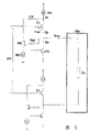
Figure 3 shows that filtration the one IF signal 301 of the present invention and produce first embodiment of the processing unit of the 2nd IF output signal 302.
At signal 301 is one not under the differential wave situation with reference to specific potential, and the input of voltage follower circuit is made up of the base stage of two transistor T1 and T2.Transistor T1 and T2 are configured to penetrate a grade follower configuration, and the differential wave 303 of a low anti-resistance is provided by their emitting stage.The emitter of transistor T1 and T2 is connected with 305 with variable current source 304, and this current source allows to provide the emitter current of a steady state value, makes the influence of the input impedance variation of its dual resonance frequency filter 206 that is not received described differential wave 303.For guaranteeing this Current Control, current source 304 links to each other with control device as described below with 305.
Dual resonance frequency filter 206 is made up of first and second resonant circuits that are of coupled connections by capacitive.
First resonant circuit is made up of capacitor C 1-C2 and inductance L 1.These elements have been determined the first resonance frequency f1, and this first resonant frequency value also depends on the characteristic of second resonant circuit.
Second resonant circuit is made up of capacitor C 3-C4 and inductance L 2.These elements have been determined the second resonance frequency f2, and its frequency values also depends on the characteristic of first resonant circuit.
The coupling of two resonant circuits realizes by capacitor C 5.Those skilled in the art provide the possibility of the frequency response that obtains dual resonance frequency filter as described in Figure 6 to the control of frequency f 1 and f2.This frequency response is characterised in that the low-down zone of a change in gain G near intermediate frequency f0, especially at frequency separation [f1, f2], this gives the credit to the interaction of first and second resonant circuits.In addition, the frequency response outside this central area decays rapidly, has shown the selectivity that this filter is very strong.
For obtaining frequency response as shown in Figure 6, those skilled in the art can fix the value of resonant circuit parts and change the value of another resonant circuit parts, up to obtaining near the stable consistent frequency response frequency f 0.
Fig. 4 has described filtering the one IF signal 301 of the present invention and has produced second embodiment of the processing unit of the 2nd IF output signal 302.
Difference among this embodiment and Fig. 3 is that the capacitive coupling of described first and second resonant circuits is that series capacitance C5-C6 by its centre-point earth constitutes.This capacitively coupled structure allows to improve the common mode inhibition to the signal 303 of wanting filtering.
As mentioned above, voltage follower circuit is associated with control device, and the bias current that constitutes the element of described circuit with maintenance is a steady state value.As shown in Figure 7, [f1, f2 promptly have very big change in the selection zone of filter at frequency separation to have the input impedance Ze of filter 206 of dual resonance frequency.In fact, near the input impedance of filter frequency being positioned at intermediate frequency f0 is got low value, and high value is positioned near the frequency place of end points of frequency separation [f1, f2].Specifically, anti-Ze has minimum value in frequency f 0, and in frequency f 1 and f2 maximum is arranged.Therefore, for a described IF signal 301 of same level, the electric current I out that is absorbed by the dual resonance frequency filter changes equally very doughtily at frequency separation [f1, f2].Because the input current Iout of filter is supplied with by the voltage follower circuit that transistor T1 and T2 constitute, cause the variation (and therefore base current changes) of transistor T1 and T2 emitter current for these variations that prevent electric current I out, control device is associated in such a way with transistor T1 and T2: the emitter current IE of transistor T1 and T2 keeps steady state value, and whether current I out does not change.
Fig. 5 has described the embodiment of described control device of the present invention.Because an IF signal 301 is differential waves, therefore same control device is associated with transistor T1 and T2.Below the control device related with transistor T1 only described.
Control device includes the power supply 501 of a steady state value IS, transistor 502, current source 503, resistor 504 and transistor 505.When electric current I out increases, trend towards making electric current I E to increase, trend towards under the current IS controlled condition, making electric current I M to reduce.By element 502-503, electric current I M reduces to cause reducing of electric current I D, and this brings constant equilibrium valve to IE.By changing electric current I D, this control allows total current IE=(Iout+ID) to remain on a steady state value.It is constant that the base current of transistor T1 also keeps, and irrelevant with the variation of electric current I out, this just allows T1 at base-emitter one dynamic constant impedance to be arranged.In other words, the base-emitter voltage Vbe of transistor T1 keeps constant.
In this way, the voltage follower circuit that the transistor T1 that is associated with control device as previously mentioned constitutes can obtain a single gain for the entire spectrum of selected channel.
Fig. 8 example use the equipment 801 of tuner 802 as shown in Figure 1, this tuner 802 is realized with reference to Fig. 23,4 and 5 described characteristics of the present invention.This device-specific converts thereof into IF signal 804 in receiving RF signal 803, and by demodulating equipment 806 restituted signals 804 to produce demodulated output signal 805.Can comprise that at RF signal 803 tuner 802 is mixed types under the situation of channel of modulating according to analogue technique and the channel of modulating according to digital technology.
For example, this equipment 801 is top setting box types, is exclusively used in to receive the RF vision signal 803 that sends by a cable system 807.IF signal 804 by tuner supply of the present invention then is significantly enlarged, and processing means 806 is demodulated to by the visual video content of display unit 808.
In Another Application, tuner of the present invention directly is incorporated in the television set.
From the angle of implementing, should form by discrete elements or integrated circuit component with reference to the element of the described tuner of the present invention of Fig. 4.Particularly the element of current controlled voltage follower circuit can be integrated in the integrated circuit.
Tuner of the present invention preferably is applicable to processing according to QAM digital technology modulated RF signal, allows in this case the expection channel is accurately selected, and has suppressed the frequency content of adjacent channel simultaneously.Particularly this tuner is applicable to the RF signal of handling the DVB type that transmits on land, is applicable to that also processing is according to the analogue technique modulated RF signal.
The present invention is described in conjunction with the tuner of single conversion, and wherein single frequency mixer is used to RF signal transformation is become the IF signal.The present invention also can be used for using the tuner of the different transform of several frequency mixers.In this case, it is just passable to be placed on the output of the frequency mixer that the IF signal is provided according to the described processing unit of the present invention of Fig. 2.
Should be noted in the discussion above that the present invention not only is confined to described embodiment, under the condition that does not deviate from the scope of the invention, those skilled in the art it is contemplated that multiple alternative.Particularly, it is contemplated that the dissimilar Current Control (for example, not having the control of feedback loop) of voltage follower circuit, and imagination uses in the dual resonance frequency filter perception to connect.
Claims (5)
1. tuner that RF signal transformation is become the IF output signal, described tuner comprises that one is used to produce the frequency mixer of an IF signal, thereby be used for the processing unit that the described IF signal of filtering produces described IF output signal, it is characterized in that processing unit comprises:
-receive a described IF voltage of signals follower circuit, be used to produce a Low ESR the 2nd IF signal,
-control device, the bias current value of controlling described voltage follower circuit is a steady state value,
-have the filter of dual resonance frequency, be used for described the 2nd IF signal of filtering and produce described IF output signal.
2. tuner according to claim 1 is characterized in that the filter with dual resonance frequency comprises two resonant circuits that connect by coupling device.
3. tuner according to claim 2 is characterized in that described coupling device comprises a capacitive couplings.
One kind be used to receive with conversion RF signal be the top setting box of IF output signal, it is characterized in that it comprises a tuner as claimed in claim 1.
5. a television equipment is characterized in that it comprises a tuner as claimed in claim 1.
Applications Claiming Priority (2)
| Application Number | Priority Date | Filing Date | Title |
|---|---|---|---|
| FR01/15312 | 2001-11-27 | ||
| FR0115312A FR2832874A1 (en) | 2001-11-27 | 2001-11-27 | TUNER COMPRISING A SELECTIVE FILTER |
Publications (2)
| Publication Number | Publication Date |
|---|---|
| CN1421995A CN1421995A (en) | 2003-06-04 |
| CN100379146C true CN100379146C (en) | 2008-04-02 |
Family
ID=8869825
Family Applications (1)
| Application Number | Title | Priority Date | Filing Date |
|---|---|---|---|
| CNB021606307A Expired - Fee Related CN100379146C (en) | 2001-11-27 | 2002-11-23 | Tuner containing selective wave filter |
Country Status (8)
| Country | Link |
|---|---|
| US (1) | US20030124996A1 (en) |
| EP (1) | EP1315295B1 (en) |
| JP (1) | JP4236915B2 (en) |
| KR (1) | KR20030043725A (en) |
| CN (1) | CN100379146C (en) |
| AT (1) | ATE363153T1 (en) |
| DE (1) | DE60220238T2 (en) |
| FR (1) | FR2832874A1 (en) |
Families Citing this family (4)
| Publication number | Priority date | Publication date | Assignee | Title |
|---|---|---|---|---|
| EP1563602A2 (en) * | 2002-11-08 | 2005-08-17 | Koninklijke Philips Electronics N.V. | A flat intermediate if filter for tuners |
| US20090122928A1 (en) * | 2007-11-13 | 2009-05-14 | Horizon Semiconductors Ltd. | Apparatus and method for frequency estimation in the presence of narrowband gaussian noise |
| GB2465037B (en) * | 2009-03-20 | 2012-04-04 | Innovision Res & Tech Plc | Near field rf communications apparatus |
| CN111106811B (en) * | 2019-12-23 | 2023-09-19 | 同方电子科技有限公司 | Double-end constant-resistance filtering assembly |
Citations (5)
| Publication number | Priority date | Publication date | Assignee | Title |
|---|---|---|---|---|
| US3860757A (en) * | 1973-06-25 | 1975-01-14 | Gte Automatic Electric Lab Inc | Lowpass circuit for physical party line applications in subscriber carrier telephone system |
| US4244008A (en) * | 1979-07-30 | 1981-01-06 | Siemens Corporation | Read back compensation circuit for a magnetic recording device |
| US5760641A (en) * | 1995-03-15 | 1998-06-02 | Plessey Semiconductors Limited | Controllable filter arrangement |
| US5887246A (en) * | 1996-12-06 | 1999-03-23 | U.S. Philips Corporation | Amplifier circuit for an intermediate-frequency signal of a radio receiver |
| US6285865B1 (en) * | 1998-11-12 | 2001-09-04 | Broadcom Corporation | System and method for on-chip filter tuning |
Family Cites Families (23)
| Publication number | Priority date | Publication date | Assignee | Title |
|---|---|---|---|---|
| US4374437A (en) * | 1980-12-29 | 1983-02-15 | Zenith Radio Corporation | Variable ramp speed TV tuning system for rapid channel tuning |
| EP0176069A1 (en) * | 1984-09-24 | 1986-04-02 | Siemens Aktiengesellschaft | High-pass filter with amplifier |
| JPH0691405B2 (en) * | 1987-10-13 | 1994-11-14 | 富士通株式会社 | Bandpass filter with variable center frequency |
| US4973915A (en) * | 1989-11-13 | 1990-11-27 | Hewlett-Packard Company | Feed forward differential equalizer for narrowing the signal pulses of magnetic heads |
| US5649312A (en) * | 1994-11-14 | 1997-07-15 | Fujitsu Limited | MMIC downconverter for a direct broadcast satellite low noise block downconverter |
| US6356736B2 (en) * | 1997-02-28 | 2002-03-12 | Maxim Integrated Products, Inc. | Direct-conversion tuner integrated circuit for direct broadcast satellite television |
| US5912798A (en) * | 1997-07-02 | 1999-06-15 | Landsten Chu | Dielectric ceramic filter |
| US6070061A (en) * | 1997-10-03 | 2000-05-30 | Zenith Electronics Corporation | Adjacent channel rejection in double conversion tuner |
| US5926752A (en) * | 1998-01-15 | 1999-07-20 | Trw Inc. | Apparatus and method for remote convenience message transmission and control with a tunable filter receiver |
| JPH11308541A (en) * | 1998-04-17 | 1999-11-05 | Sony Corp | Tuner circuit |
| JP2000195003A (en) * | 1998-12-25 | 2000-07-14 | Mitsubishi Electric Corp | Signal amplification circuit for mr element |
| JP3471648B2 (en) * | 1999-02-26 | 2003-12-02 | 富士通カンタムデバイス株式会社 | Power amplifier circuit and its bias circuit |
| JP2001007682A (en) * | 1999-06-17 | 2001-01-12 | Hitachi Kokusai Electric Inc | Tuning frequency variable filter |
| US6252457B1 (en) * | 1999-12-28 | 2001-06-26 | Mitsubishi Denki Kabushiki Kaisha | Differential amplifier circuit |
| US6714069B1 (en) * | 2000-06-30 | 2004-03-30 | Koninklijke Philips Electronics N.V. | Self-configurable amplifier circuit |
| KR100759508B1 (en) * | 2000-08-01 | 2007-09-18 | 정연문 | High-quency oscillation circuit having a feedback circuit |
| JP2002354358A (en) * | 2001-05-24 | 2002-12-06 | Alps Electric Co Ltd | Television tuner |
| US7579912B2 (en) * | 2001-08-15 | 2009-08-25 | Broadcom Corporation | Method and system for multiple tuner application using a low noise broadband distribution amplifier |
| US7123083B2 (en) * | 2001-10-15 | 2006-10-17 | Micronas Gmbh | Active filter circuit with operational amplifier |
| KR100474085B1 (en) * | 2003-02-07 | 2005-03-10 | 인티그런트 테크놀로지즈(주) | Circuit and Method for DC offset Calibration and Signal Processing Apparatus using the same |
| US6744308B1 (en) * | 2002-08-30 | 2004-06-01 | Microtune (Texas), L.P. | System and method for establishing the input impedance of an amplifier in a stacked configuration |
| JP2004312668A (en) * | 2003-03-25 | 2004-11-04 | Sharp Corp | Low-noise converter |
| GB2401498B (en) * | 2003-05-07 | 2006-02-22 | Zarlink Semiconductor Ltd | Tuner |
-
2001
- 2001-11-27 FR FR0115312A patent/FR2832874A1/en not_active Withdrawn
-
2002
- 2002-11-20 AT AT02079813T patent/ATE363153T1/en not_active IP Right Cessation
- 2002-11-20 DE DE60220238T patent/DE60220238T2/en not_active Expired - Lifetime
- 2002-11-20 EP EP02079813A patent/EP1315295B1/en not_active Expired - Lifetime
- 2002-11-21 US US10/301,227 patent/US20030124996A1/en not_active Abandoned
- 2002-11-23 CN CNB021606307A patent/CN100379146C/en not_active Expired - Fee Related
- 2002-11-26 KR KR1020020073774A patent/KR20030043725A/en not_active Application Discontinuation
- 2002-11-27 JP JP2002344350A patent/JP4236915B2/en not_active Expired - Fee Related
Patent Citations (5)
| Publication number | Priority date | Publication date | Assignee | Title |
|---|---|---|---|---|
| US3860757A (en) * | 1973-06-25 | 1975-01-14 | Gte Automatic Electric Lab Inc | Lowpass circuit for physical party line applications in subscriber carrier telephone system |
| US4244008A (en) * | 1979-07-30 | 1981-01-06 | Siemens Corporation | Read back compensation circuit for a magnetic recording device |
| US5760641A (en) * | 1995-03-15 | 1998-06-02 | Plessey Semiconductors Limited | Controllable filter arrangement |
| US5887246A (en) * | 1996-12-06 | 1999-03-23 | U.S. Philips Corporation | Amplifier circuit for an intermediate-frequency signal of a radio receiver |
| US6285865B1 (en) * | 1998-11-12 | 2001-09-04 | Broadcom Corporation | System and method for on-chip filter tuning |
Non-Patent Citations (2)
| Title |
|---|
| FM立体声调谐器的新技术. 李泰桢.电声技术,第03期. 1980 * |
| 声表面波双模谐振滤波器的计算机优化设计. 徐恭勤.集美航海学院学报,第14卷第04期. 1996 * |
Also Published As
| Publication number | Publication date |
|---|---|
| JP4236915B2 (en) | 2009-03-11 |
| DE60220238D1 (en) | 2007-07-05 |
| DE60220238T2 (en) | 2008-01-24 |
| EP1315295B1 (en) | 2007-05-23 |
| ATE363153T1 (en) | 2007-06-15 |
| CN1421995A (en) | 2003-06-04 |
| EP1315295A1 (en) | 2003-05-28 |
| KR20030043725A (en) | 2003-06-02 |
| JP2003168993A (en) | 2003-06-13 |
| US20030124996A1 (en) | 2003-07-03 |
| FR2832874A1 (en) | 2003-05-30 |
Similar Documents
| Publication | Publication Date | Title |
|---|---|---|
| KR100433073B1 (en) | Rf filter arrangement with image trap | |
| US7336939B2 (en) | Integrated tracking filters for direct conversion and low-IF single conversion broadband filters | |
| US7756500B1 (en) | Active inductor circuits for filtering in a cable tuner circuit | |
| US20010016950A1 (en) | Cable modem tuner | |
| CN1264517A (en) | Direct-conversion tuner integrated circuit for direct broadcast sat ellite television | |
| US4710970A (en) | Method of and apparatus for generating a frequency modulated ultrahigh frequency radio transmission signal | |
| US7151919B2 (en) | Method for forming an intermediate frequency signal in a mixer, and a mixer | |
| US6124766A (en) | Frequency converter circuit for cable modem tuner | |
| JP2000307444A (en) | Television signal receiving tuner | |
| CN100379146C (en) | Tuner containing selective wave filter | |
| US4569085A (en) | Oscillator control circuit in an F.M. receiver | |
| US3742130A (en) | Television receiver incorporating synchronous detection | |
| US4794458A (en) | Modulation device | |
| US3997856A (en) | Frequency discriminator circuit arrangement | |
| US7272187B2 (en) | Filter circuit and radio apparatus | |
| US4912775A (en) | RF converter circuit | |
| CA2000167A1 (en) | Tuner-demodulator device | |
| US4850039A (en) | Transistor mixer | |
| JPH0730456A (en) | Television tuner | |
| JPH11284537A (en) | Tuner | |
| US20040053593A1 (en) | Signal mixers | |
| JP3276377B2 (en) | CATV converter | |
| Ashby et al. | A SiGe transmitter chipset for CATV video-on-demand systems | |
| JPS615632A (en) | Television tuner | |
| JPS591011B2 (en) | television receiver tuner |
Legal Events
| Date | Code | Title | Description |
|---|---|---|---|
| C06 | Publication | ||
| PB01 | Publication | ||
| C10 | Entry into substantive examination | ||
| SE01 | Entry into force of request for substantive examination | ||
| C14 | Grant of patent or utility model | ||
| GR01 | Patent grant | ||
| C17 | Cessation of patent right | ||
| CF01 | Termination of patent right due to non-payment of annual fee |
Granted publication date: 20080402 Termination date: 20101123 |