CN100377813C - Method of forming a housing having a thin wall and the housing - Google Patents
Method of forming a housing having a thin wall and the housing Download PDFInfo
- Publication number
- CN100377813C CN100377813C CNB2006100741377A CN200610074137A CN100377813C CN 100377813 C CN100377813 C CN 100377813C CN B2006100741377 A CNB2006100741377 A CN B2006100741377A CN 200610074137 A CN200610074137 A CN 200610074137A CN 100377813 C CN100377813 C CN 100377813C
- Authority
- CN
- China
- Prior art keywords
- knock
- wall
- mechanograph
- receiving portion
- pin receiving
- Prior art date
- Legal status (The legal status is an assumption and is not a legal conclusion. Google has not performed a legal analysis and makes no representation as to the accuracy of the status listed.)
- Active
Links
Images


Classifications
-
- B—PERFORMING OPERATIONS; TRANSPORTING
- B22—CASTING; POWDER METALLURGY
- B22D—CASTING OF METALS; CASTING OF OTHER SUBSTANCES BY THE SAME PROCESSES OR DEVICES
- B22D17/00—Pressure die casting or injection die casting, i.e. casting in which the metal is forced into a mould under high pressure
- B22D17/20—Accessories: Details
- B22D17/22—Dies; Die plates; Die supports; Cooling equipment for dies; Accessories for loosening and ejecting castings from dies
- B22D17/2236—Equipment for loosening or ejecting castings from dies
Abstract
According to one embodiment, a housing is formed by using a pair of metal molds. The housing includes a first wall, second walls projecting from the first wall, and bosses projecting from the first wall. A molten material is filled into a molding space defined between the metal molds, and thereby a molded article having a shape corresponding to the housing is molded. The molded article has a plurality of first pin-receiving portions serving as the bosses, and a plurality of second pin-receiving portions projecting from the second walls. The first and the second pin-receiving portions are pushed by a plurality of ejector pins, and thereby the molded article is ejected from the metal molds.
Description
Technical field
One embodiment of the present of invention relate to the method for shell of the electronic equipment of formation such as portable computer, more particularly, relate to by using a plurality of knock-pins to eject method as the mechanograph of shell element body from metal die.In addition, the present invention also relates to by between the pair of metal mould, injecting the molded shell of material of fusing.
Recently, have shell that magnesium alloy makes such as the electronic equipment of portable computer for known to everybody.The advantage that the shell of being made by magnesium alloy has is, can reach reducing of weight and thickness easilier, and the shell that stiffness is made than synthetic resin or aluminium alloy more can be guaranteed.
Produced in a large number by using device for molding by the shell that magnesium alloy is made.Device for molding has a pair of metal die that engages separably.Molding space is formed between the metal die.The magnesium alloy of fusing is injected into molding space and hardening therein, thereby obtains to have the mechanograph with the shell corresponding shape.Mechanograph ejects from mould, then stands chemical treatment, priming paint coating, painted and apply the processing of glazing coating or the like.
When mechanograph ejects, adopt the method for using a plurality of knock-pins usually from mould.Knock-pin upwards pushes away mechanograph from one of them metal die, and can vertically be attached to movably on one of them metal die.The wide scope on the Overmolded product thereby knock-pin is scatter makes them upwards to promote mechanograph and can not make the goods deflection.
On the other hand, the basic thickness of magnesium alloy case rule of thumb is set to 0.8mm or thinner.Therefore, be formed as the mechanograph of shell element body and have very little thickness.Thereby if adopt conventional knock-pin, when mechanograph ejected from mould, very thin mechanograph may be subjected to the harmful effect of the thrust that applies from knock-pin.
The warpage if mechanograph distortion, its surface as outer surface become.After the glazing coating was applied to mechanograph, this warpage caused light diffusion.Therefore, seeming especially remarkable by warpage in the shell of mechanograph coating glazing coating acquisition.This causes the outward appearance of shell to degenerate.
Summary of the invention
An object of the present invention is to provide a kind of formation does not have the method for the high-quality shell of warpage or distortion, when mechanograph ejects from metal die, can bear the thrust from knock-pin fully.
Another object of the present invention is the high-quality shell that obtains not have warpage or distortion.
In order to achieve the above object, method according to an aspect of the present invention be form have first wall, the method for the shell of a plurality of second wall that protrudes from first wall and a plurality of protuberances that on the position that is different from second wall, protrude from first wall, this method comprises: prepare the pair of metal mould; The material of fusing is injected the molding space that limits between the metal die, the molded thus mechanograph that has with the shell corresponding shape, this mechanograph has a plurality of first knock-pin receiving portion and a plurality of second knock-pin receiving portions that protrude from second wall as protuberance, and the size of the end surface of this second knock-pin receiving portion is greater than the thickness of second wall; With the first knock-pin receiving portion by promoting mechanographs with a plurality of knock-pins and the second knock-pin receiving portion mechanograph is ejected from metal die.
In order to reach above-mentioned another purpose, shell according to an aspect of the present invention is the shell that forms by the material that injects fusing between the pair of metal mould, and this shell comprises: the first wall with basic thickness; A plurality ofly protrude and have second wall of a plurality of knock-pin receiving portions from first wall, the size of the end surface of this second knock-pin receiving portion is greater than the thickness of second wall; With a plurality of protuberances that protrude from first wall on the position that is different from second wall, wherein when shell ejected from metal die, knock-pin receiving portion and protuberance were promoted by a plurality of knock-pins.
According to the present invention, knock-pin promotes the part with stiffness bigger than first wall of mechanograph.Therefore, mechanograph is not subjected to the harmful effect of the thrust that applies from knock-pin, and can obtain not have the high-quality shell of warpage or distortion.
Other purpose of the present invention and advantage will be illustrated in the narration below, and wherein part will be apparent from narration, perhaps can obtain understanding by practice of the present invention.Target of the present invention and advantage can be by means of hereinafter concrete means that propose and combination realize and obtain.
Description of drawings
The general structure of implementing various features of the present invention is hereinafter described with reference to the accompanying drawings.Accompanying drawing that is provided and associated description are to be used for illustrating embodiments of the invention, rather than limit the scope of the invention.
Fig. 1 is the stereogram of illustrative portable computer according to an embodiment of the invention;
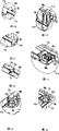
Fig. 2 is the exemplary isometric view of the case lid of first shell under rollover states according to an embodiment of the invention;
Fig. 3 is the exemplary amplification stereogram that the regional A of circle is arranged among Fig. 2;
Fig. 4 is the exemplary amplification stereogram that the area B of circle is arranged among Fig. 2;
Fig. 5 is the exemplary amplification stereogram that the zone C of circle is arranged among Fig. 2;
Fig. 6 is the exemplary amplification stereogram that the region D of circle is arranged among Fig. 2;
Fig. 7 is the exemplary amplification stereogram that the area E of circle is arranged among Fig. 2;
Fig. 8 is the exemplary amplification stereogram that the regional F of circle is arranged among Fig. 2;
Fig. 9 is the exemplary amplification stereogram that the regional G of circle is arranged among Fig. 2;
Figure 10 is the exemplary amplification stereogram that the regional H of circle is arranged among Fig. 2;
Figure 11 is the exemplary amplification stereogram that the area I of circle is arranged among Fig. 2;
Figure 12 is the exemplary amplification stereogram that the regional J of circle is arranged among Fig. 2;
Figure 13 is the exemplary amplification stereogram that the regional K of circle is arranged among Fig. 2;
Figure 14 is the exemplary amplification stereogram that the area L of circle is arranged among Fig. 2;
Figure 15 is the exemplary amplification stereogram that the regional M of circle is arranged among Fig. 2;
Figure 16 is the exemplary amplification stereogram that the regional N of circle is arranged among Fig. 2;
Figure 17 is the exemplary amplification stereogram that the regional O of circle is arranged among Fig. 2;
Figure 18 is according to an embodiment of the invention as the exemplary plan view of the display cover of the part of display unit;
Figure 19 is the exemplary generalized section that forms the mechanograph of lid according to an embodiment of the invention;
Figure 20 illustrates the exemplary sectional view that magnesium alloy according to an embodiment of the invention is injected into the state of the molding space between the pair of metal mould;
Figure 21 illustrates to use knock-pin to eject the exemplary sectional view of the state of mechanograph according to an embodiment of the invention from metal die;
Figure 22 is the exemplary isometric view that is in the mechanograph under the state that the second knock-pin receiving portion shown in Fig. 8 therefrom ejects according to an embodiment of the invention.
The specific embodiment
Hereinafter describe with reference to the accompanying drawings according to each embodiment of the present invention.Put it briefly, according to one embodiment of present invention, formation has first wall, a plurality of second walls that protrude from first wall, comprise with the method for the shell of a plurality of protuberances that on the position that is different from second wall, protrude from first wall: prepare the pair of metal mould, the material of fusing is injected the molding space that limits between the metal die, the molded thus mechanograph that has with the shell corresponding shape, this mechanograph has a plurality of first knock-pin receiving portion and a plurality of second knock-pin receiving portions that protrude from second wall as protuberance, and by with the first knock-pin receiving portion of a plurality of knock-pins promotion mechanographs and the second knock-pin receiving portion mechanograph being ejected from metal die.
Fig. 1 has illustrated the portable computer 1 as an example of electronic equipment.Portable computer 1 comprises master unit 2 and display unit 3.Master unit 2 has first shell 10.First shell 10 comprises the critical piece such as hard disk drive and printed circuit board (PCB).First shell 10 has the shape of flat boxes, has roof 11a, diapire 11b, antetheca 11c, rear wall 11d and left and right sides sidewall 11e and 11f.Roof 11a is the example of first wall.The first half of the outer surface of roof 11a is as palm support portion 12.Antetheca 11c, rear wall 11d and sidewall 11e and 11f are the examples of the 3rd wall, from the edge of roof 11a to lower convexity.
The roof 11a of first shell 10 has keyboard attachment 13.Keyboard attachment 13 is positioned at the back of palm support portion 12 and supports keyboard 14.
Panel of LCD 22 is comprised in second shell 20.Panel of LCD 22 has the screen 22a of display image.Screen 22a is exposed to second shell, 20 outsides by the peristome 20a of antetheca 21b.
Fig. 2 has illustrated the case lid 31 under rollover states.Shown in Fig. 2 to 17, on the inner surface of the part of the roof 11a of formation first shell 10 of case lid 31, a plurality of protuberance 41a form single piece to 41h and a plurality of rib shape partition wall 42a to 42e and case lid 31.Protuberance 41a is to 41h inner surface projection from roof 11a on the thickness direction of roof 11a.Partition wall 42a is the example of second wall to 42e, on the thickness direction of roof 11a from the inner surface projection of roof 11a.Protuberance 41a to 41h be arranged on partition wall 42a to the different position of 42e.
In first shell 10 and second shell 20 each all passes through to use device for molding molded.Figure 20 and 21 has illustrated the device for molding 50 of the case lid 31 that is used for molded first shell 10.Device for molding 50 comprises first metal die, 51, the second metal dies 52 and a plurality of knock-pin 53 with die cavity.
But first metal die 51 and second metal die 52 engage in the mode of vertical separation.First metal die 51 and second metal die 52 form molding space when they engage.
Shown in Fig. 2 to 17, first to the 3rd knock-pin receiving portion 56 to 58 is examples of protuberance, and each knock-pin receiving portion has generally cylindrical.First to the 3rd knock-pin receiving portion 56 to 58 from mechanograph 55 as the inner surface projection of the part of roof 11a.First to the 3rd knock-pin receiving portion 56 to 58 has separately end surface 56a to 58a.The end surface of each second knock-pin receiving portion 57 preferably have than mechanograph 55 as partition wall 42a to the bigger thickness of the part of 42e, littler than the end surface 56a of each first knock-pin receiving portion 56.Further, first to the 3rd knock-pin receiving portion 56 to 58 is set to be dispersed in the scope of broadness of the part that is used as roof 11a in the mechanograph 55.
Knock-pin 53 upwards pushes away, and ejects mechanograph 55 from second metal die 52, and can vertically be supported movably by second metal die 52.Knock-pin 53 is set in the position corresponding with first to the 3rd knock-pin receiving portion 56 to 58 of mechanograph 55, makes them upwards push away mechanograph 55 and does not make its deflection.
Next will explain the program of the case lid 31 that uses device for molding 50 molded first shells 10.
At first, first metal die 51 and second metal die 52 engage one another, thereby molding space 54 is formed between first and second metal dies 51 and 52.Then, the magnesium alloy of fusing is injected into molding space 54.When molding space 54 was injected into magnesium alloy, after the cooling cycle in several seconds, first metal die 51 and second metal die 52 moved with direction disconnected from each other.This step makes the mechanograph 55 that has with case lid 31 corresponding shape be exposed to device for molding 50 outsides, thereby moldings 55 is ejected from device for molding 50.
As shown in figure 21, when molded products 55 ejected from device for molding 50, knock-pin 53 rose.Knock-pin 53 is met the top end surface 56a of first to the 3rd knock-pin receiving portion 56 to 58 of mechanograph 55 to 58a, and upwards pushes away mechanograph 55 from second metal die 52.As a result, mechanograph 55 separates from second metal die 52, thereby mechanograph 55 is ejected from device for molding 50.
After mechanograph 55 ejects, form protuberance 41a to 41h by processing the first knock-pin receiving portion 56 from device for molding 50.In the second knock-pin receiving portion 57, the second knock-pin receiving portion 57 that holds that does not hinder the primary clustering in first shell 10 can be retained in the mechanograph 55.Hinder some second knock-pin receiving portions 57 of primary clustering from mechanograph, to be excised.Thereby, can be clear that the comparison between Fig. 8 and Figure 22 that some second knock-pin receiving portions 57 are removed from partition wall 42c.If necessary, some the 3rd knock-pin receiving portions 58 are also removed from mechanograph 55.
After the process finishing of mechanograph 55, mechanograph 55 is through antirust chemical treatment.Then, mechanograph is through priming paint coating, colouring with apply processing as the glazing coating of the example of high gloss coating.The coating of gloss coating is for abrasion resistance that improves mechanograph 55 and presentation quality, but is not limited to use the coating of celluloid paint.
Through above-mentioned steps, finish as the case lid 31 of the part of first shell 10.
According to the said method that forms case lid 31, when the mechanograph 55 of the element body that is used as case lid 31 ejected from device for molding 50, knock-pin 53 upwards pushed away first to the 3rd knock-pin receiving portion 56 to 58 of mechanograph 55.Each first to the 3rd knock-pin receiving portion 56 to 58 all has the bigger thickness of part as thin roof 11a than mechanograph 55, and has high stiffness.This means that knock-pin 53 upwards promotes to have in the mechanograph 55 part of high stiffness.
In other words, knock-pin 53 does not upwards push away in the mechanograph 55 part of thin and easy deformation, and mechanograph 55 is not subjected to the harmful effect of the thrust that knock-pin 53 applies.Therefore, be done, can obtain to have good surface appearance and not cause light diffusing case lid 31 as the mechanograph 55 of the case lid 31 that does not almost have warpage or distortion.
The casing 32 of first shell 10 can use the device for molding that is similar to case lid 31 to form.Therefore, the explanation to the method that forms casing 32 is omitted.
Next will explain the method for the display cover 33 that forms second shell 20.The part as rear wall 21a of display cover 33 has the size of covering liquid crystal display 22 panels, and has the very little thickness of 0.6mm.
With the form identical with the device for molding 50 that forms case lid 31, the device for molding of molded display cover 33 comprises first metal die 51, second metal die 52 and a plurality of knock-pin 53.The molding space 54 that limits between first metal die 51 and second metal die 52 is used to obtain to have the mechanograph 61 with display cover shown in Figure 180 3 corresponding shape.
Further, if mechanograph 61 also have a plurality of from as the jut 65a of the part projection of rear wall 21a to 65d with from upstanding wall 66 as the part projection of rear wall 21a, then jut 65a is arranged in the outer regions 63 to 65d and upstanding wall 66.Upstanding wall 66 supports panel of LCD 22, and has some knock-pin receiving portions 62.Therefore, first and second metal patterns its 51 and 52 be designed to make knock-pin receiving portion 62, protuberance 65a to form with mechanograph 61 to 65d and upstanding wall 66.
Knock-pin 53 upwards pushes away mechanograph 61 and mechanograph 61 is ejected from second metal die 52, can vertically be supported movably by second metal die 52.Knock-pin 53 be arranged on the knock-pin receiving portion 62 of mechanograph 61 and protuberance 65a to the corresponding position of 65d, so that they can upwards push away mechanograph 61 and not make its deflection.
In order to form display cover 33, at first, the magnesium alloy of fusing is injected into the molding space 54 of device for molding 50.Then, through after the cooling cycle of several seconds, first metal die 51 and second metal die 52 move with direction disconnected from each other, and after this mechanograph 61 is therefrom ejected.
When mechanograph 61 was ejected from device for molding 50, knock-pin 53 rose.Knock-pin 53 is run into the knock-pin receiving portion 62 of molded products 61 and protuberance 65a to 65d, and upwards pushes away mechanograph 61 from second metal die 52.As a result, mechanograph 61 separates with second metal die 52, and mechanograph 61 ejects from device for molding 50 thus.
After mechanograph 61 ejected from device for molding 50, protuberance 65a was processed to 65d, and if necessary, some second knock-pin receiving portions 62 are to excise from mechanograph 61 with case lid 31 identical modes.Then, mechanograph 61 applies, paints and applies the processing of gloss coating through antirust chemical treatment, priming paint.Through above-mentioned steps, finish as the display cover 33 of the part of second shell 20.
According to the method for above-mentioned formation display cover 33, when the mechanograph 61 as the element body of display cover 33 ejected from device for molding 50, knock-pin 53 upwards pushed away the knock-pin receiving portion 62 of mechanograph 61 and protuberance 65a to 65d.Therefore, knock-pin 53 does not upwards push away in the mechanograph 61 the very thin part corresponding to rear wall 21a, so mechanograph 61 is not subjected to the harmful effect of the thrust that applies from knock-pin 53.Therefore, be done as the mechanograph 61 that does not almost have warpage or distortion and have a high-quality display cover 33.
Therefore, even moldings 61 also can obtain to have the display cover 33 of good appearance through the processing of gloss coating.
The display frame 34 of second shell 20 forms by using the device for molding similar with being used for display cover 33.Therefore, the explanation to the method that forms display frame 34 is omitted.
The invention is not restricted to shell of portable computer and forming method thereof.For example, the present invention may be implemented as the shell of the electronic equipment except portable computer or miscellaneous equipment.
Though certain embodiments of the present invention is described, these embodiment only as an example mode present, rather than will limit the scope of the invention.In fact, novel method described herein can embody with various alternate manners; In addition, can carry out various omissions, substitute and change with the form of method described herein and do not deviate from spirit of the present invention.Attached claim and content of equal value thereof are intended to cover such form and the modification that drops within the scope and spirit of the present invention.
Claims (10)
1. method that forms shell (10), described shell (10) has first wall (11a), a plurality of second wall (42a, 42b, 42c that protrudes from first wall (11a), 42d 42e) is being different from second wall (42a, 42b with a plurality of, 42c, 42d, the protuberance (41a that protrudes from first wall (11a) on position 42e), 41b, 41c, 41d, 41e, 41f, 41g, 41h), it is characterized in that, comprising:
Prepare pair of metal mould (51,52);
The material of fusing is injected metal die (51,52) molding space (54) that limits between, thereby the molded mechanograph (55) that has with shell (10) corresponding shape, mechanograph (55) has a plurality of as protuberance (41a, 41b, 41c, 41d, 41e, 41f, 41g, the first knock-pin receiving portion (56) 41h) and a plurality of from second wall (42a, 42b, 42c, 42d, 42e) the second knock-pin receiving portion (57) of Tu Chuing, the size of the end surface (57a) of this second knock-pin receiving portion (57) is greater than the second wall (42a, 42b, 42c, 42d, thickness 42e); With
By the first knock-pin receiving portion (56) and the second knock-pin receiving portion (57) that promotes mechanograph (55) with a plurality of knock-pins (53) mechanograph (55) is ejected from metal die (51,52).
2. the method for claim 1 is characterized in that, after mechanograph (55) ejects from metal die (51,52), by process the first knock-pin receiving portion (56) form protuberance (41a, 41b, 41c, 41d, 41e, 41f, 41g, 41h).
3. the method for claim 1 is characterized in that, after mechanograph (55) ejected from metal die (51,52), at least one second knock-pin receiving portion (57) was removed from mechanograph (55).
4. the method for claim 1, it is characterized in that, the first knock-pin receiving portion (56) and the second knock-pin receiving portion (57) have the end surface (56a of the knock-pin (53) that contacts respectively separately, 57a), and the end surface (57a) of the second knock-pin receiving portion (57) have the littler size of size than the end surface (56a) of the first knock-pin receiving portion (56).
5. the method for claim 1 is characterized in that, when mechanograph (55) when being molded, form the 3rd wall (11c, 11d, the 11e that is erected on first wall (11a) edge together, 11f) with a plurality of from the 3rd wall (11c, 11d, 11e, 11f) the 3rd knock-pin receiving portion (58) of Tu Chuing, and by promoting first to the 3rd knock-pin receiving portion (56,57,58) by separately knock-pin (53), mechanograph (55) is ejected from metal die (51,52).
6. as any described method in the claim 1 to 5, it is characterized in that described material is a magnesium alloy.
7. shell that forms by the material that injects fusing between pair of metal mould (51,52) is characterized in that described shell comprises:
First wall (11a) with basic thickness;
A plurality of second wall (42a, 42b, 42c, 42d that protrude and have a plurality of knock-pin receiving portions (57) from first wall (11a), 42e), the size of the end surface (57a) of this knock-pin receiving portion (57) is greater than second wall (42a, 42b, 42c, 42d, thickness 42e); With
A plurality of be different from second wall (42a, 42b, 42c, 42d, the protuberance that protrudes from first wall (11a) on position 42e) (41a, 41b, 41c, 41d, 41e, 41f, 41g, 41h),
Wherein, when shell is ejected from metal die (51,52), knock-pin receiving portion (57) and protuberance (41a, 41b, 41c, 41d, 41e, 41f, 41g 41h) is promoted by a plurality of knock-pins (53).
8. shell as claimed in claim 7 is characterized in that described material is a magnesium alloy.
9. as claim 7 or 8 described shells, it is characterized in that the basic thickness of described first wall (11a) is 0.8mm or littler.
10. as claim 7 or 8 described shells, it is characterized in that, and knock-pin receiving portion (57) and protuberance (41a, 41b, 41c, 41d, 41e, 41f, 41g 41h) is dispersed in the scope of broadness of first wall (11a).
Applications Claiming Priority (2)
| Application Number | Priority Date | Filing Date | Title |
|---|---|---|---|
| JP2005118640A JP4772365B2 (en) | 2005-04-15 | 2005-04-15 | Case forming method |
| JP2005118640 | 2005-04-15 |
Publications (2)
| Publication Number | Publication Date |
|---|---|
| CN1846902A CN1846902A (en) | 2006-10-18 |
| CN100377813C true CN100377813C (en) | 2008-04-02 |
Family
ID=37076762
Family Applications (1)
| Application Number | Title | Priority Date | Filing Date |
|---|---|---|---|
| CNB2006100741377A Active CN100377813C (en) | 2005-04-15 | 2006-03-24 | Method of forming a housing having a thin wall and the housing |
Country Status (3)
| Country | Link |
|---|---|
| US (2) | US7458412B2 (en) |
| JP (1) | JP4772365B2 (en) |
| CN (1) | CN100377813C (en) |
Families Citing this family (11)
| Publication number | Priority date | Publication date | Assignee | Title |
|---|---|---|---|---|
| JP5128916B2 (en) * | 2007-11-28 | 2013-01-23 | リョービ株式会社 | Die casting mold and die casting method |
| TWM394494U (en) * | 2010-06-24 | 2010-12-11 | Wistron Corp | External extension for holding a portable computer and computer system therewith |
| CN102858116A (en) * | 2011-06-29 | 2013-01-02 | 深圳富泰宏精密工业有限公司 | Electronic device, nut screw thereof and assembly method of electronic device |
| JP5917899B2 (en) | 2011-11-29 | 2016-05-18 | 日産自動車株式会社 | Thin battery and method of manufacturing thin battery |
| US20140150982A1 (en) * | 2012-12-04 | 2014-06-05 | Microsoft Corporation | Metal Alloy Injection Techniques |
| CN102941332B (en) * | 2012-12-04 | 2015-05-20 | 宁波勋辉电器有限公司 | Movable die pull-back structure of die casting die |
| KR101481454B1 (en) * | 2014-07-14 | 2015-01-12 | 재영솔루텍 주식회사 | Injection mold for inner cover member of electronic device and method for forming inner cover member using the same |
| CN105328164A (en) * | 2015-11-30 | 2016-02-17 | 苏州市金翔钛设备有限公司 | U-shaped die-casting mold ejector pin provided with spring |
| CN107876708A (en) * | 2017-11-17 | 2018-04-06 | 李正梅 | Motor casing casting mould |
| CN110125363A (en) * | 2019-06-24 | 2019-08-16 | 东莞东运镁业有限公司 | A kind of die-casting process of notebook computer casing |
| CN113492206A (en) * | 2020-04-02 | 2021-10-12 | 昆山华复精密金属有限公司 | Auxiliary ejection structure |
Citations (8)
| Publication number | Priority date | Publication date | Assignee | Title |
|---|---|---|---|---|
| JP2000025062A (en) * | 1998-07-10 | 2000-01-25 | Cluster Technology Kk | Molding of thermosetting resin |
| CN2384251Y (en) * | 1999-02-23 | 2000-06-21 | 谢炎基 | Top cover for notebook computer |
| JP2002166429A (en) * | 2000-11-30 | 2002-06-11 | Sumitomo Bakelite Co Ltd | Molding method and molding die |
| JP2002178338A (en) * | 2000-12-11 | 2002-06-26 | Matsushita Electric Ind Co Ltd | Ejection method and mold with ejection pin |
| CN1096904C (en) * | 1999-06-03 | 2002-12-25 | 三井金属矿业株式会社 | Magnesium alloy pressure die casting method and articles |
| WO2003037602A1 (en) * | 2001-10-26 | 2003-05-08 | Krauss-Maffei Kunststofftechnik Gmbh | Device for removing an injection moulded substrate from an injection-moulding tool, and injection-moulding machine equipped with same |
| CN1576066A (en) * | 2003-06-25 | 2005-02-09 | 丰田自动车株式会社 | Cast suspension beam structure |
| CN1579738A (en) * | 2003-08-06 | 2005-02-16 | 住友电装株式会社 | Mold for injection molding and a method of operating said mold |
Family Cites Families (18)
| Publication number | Priority date | Publication date | Assignee | Title |
|---|---|---|---|---|
| US2304899A (en) * | 1941-01-10 | 1942-12-15 | Western Electric Co | Die casting machine |
| JPS5843178B2 (en) * | 1979-01-26 | 1983-09-26 | 本田技研工業株式会社 | Method of filling molten metal in vertical die casting machine |
| US4308307A (en) * | 1980-02-01 | 1981-12-29 | Ford Motor Company | Plastic panel for vehicular exterior |
| JPS57175068A (en) * | 1981-04-21 | 1982-10-27 | Toyo Kikai Kinzoku Kk | Removing method for product in die casting machine |
| US4825603A (en) * | 1987-03-23 | 1989-05-02 | Farley, Inc. | Elevated floor plate |
| JP2825398B2 (en) * | 1992-07-13 | 1998-11-18 | 本田技研工業株式会社 | Mold release device for casting work |
| JP3016331B2 (en) * | 1993-09-07 | 2000-03-06 | 富士通株式会社 | Manufacturing method of electronic equipment housing |
| US5566743A (en) * | 1994-05-02 | 1996-10-22 | Guergov; Milko G. | Method of injecting molten metal into a mold cavity |
| JPH08267210A (en) * | 1995-01-19 | 1996-10-15 | Nippon Light Metal Co Ltd | Large sized integrated thin cast product, production thereof and metallic mold for casting |
| JPH09253830A (en) * | 1996-03-19 | 1997-09-30 | Asahi Tec Corp | Cast product and casting device for its product |
| JP2000005859A (en) * | 1998-06-19 | 2000-01-11 | Toshiba Corp | Electronic equipment, its manufacture, and die device |
| US6206682B1 (en) * | 1998-10-05 | 2001-03-27 | Itt Manufacturing Enterprises, Inc. | Molding accelerated stripper-ejector system |
| US5915453A (en) * | 1998-10-13 | 1999-06-29 | Kennedy Die Casting, Inc. | Multiple part die casting die |
| JP2001113353A (en) * | 1999-10-15 | 2001-04-24 | Fujitsu Kasei Kk | Die device for injection molding for magnesium alloy |
| JP2001205419A (en) * | 2000-01-24 | 2001-07-31 | Matsushita Electric Ind Co Ltd | Injection molding method for magnesium alloy and molded goods obtained by the same |
| JP2002018626A (en) * | 2000-07-05 | 2002-01-22 | Tenma Mag-Tec Kk | Molded product of magnesium alloy |
| JP3617958B2 (en) * | 2001-03-07 | 2005-02-09 | 株式会社東芝 | Housing for display device |
| JP2003053504A (en) * | 2001-08-08 | 2003-02-26 | Mitsuwa Denki Kogyo Kk | Metallic mold for metallic formed body and method for producing metallic formed body using the same |
-
2005
- 2005-04-15 JP JP2005118640A patent/JP4772365B2/en active Active
-
2006
- 2006-03-16 US US11/376,893 patent/US7458412B2/en active Active
- 2006-03-24 CN CNB2006100741377A patent/CN100377813C/en active Active
-
2008
- 2008-11-05 US US12/265,650 patent/US20090052125A1/en not_active Abandoned
Patent Citations (8)
| Publication number | Priority date | Publication date | Assignee | Title |
|---|---|---|---|---|
| JP2000025062A (en) * | 1998-07-10 | 2000-01-25 | Cluster Technology Kk | Molding of thermosetting resin |
| CN2384251Y (en) * | 1999-02-23 | 2000-06-21 | 谢炎基 | Top cover for notebook computer |
| CN1096904C (en) * | 1999-06-03 | 2002-12-25 | 三井金属矿业株式会社 | Magnesium alloy pressure die casting method and articles |
| JP2002166429A (en) * | 2000-11-30 | 2002-06-11 | Sumitomo Bakelite Co Ltd | Molding method and molding die |
| JP2002178338A (en) * | 2000-12-11 | 2002-06-26 | Matsushita Electric Ind Co Ltd | Ejection method and mold with ejection pin |
| WO2003037602A1 (en) * | 2001-10-26 | 2003-05-08 | Krauss-Maffei Kunststofftechnik Gmbh | Device for removing an injection moulded substrate from an injection-moulding tool, and injection-moulding machine equipped with same |
| CN1576066A (en) * | 2003-06-25 | 2005-02-09 | 丰田自动车株式会社 | Cast suspension beam structure |
| CN1579738A (en) * | 2003-08-06 | 2005-02-16 | 住友电装株式会社 | Mold for injection molding and a method of operating said mold |
Also Published As
| Publication number | Publication date |
|---|---|
| JP2006297409A (en) | 2006-11-02 |
| JP4772365B2 (en) | 2011-09-14 |
| US20090052125A1 (en) | 2009-02-26 |
| CN1846902A (en) | 2006-10-18 |
| US20060231230A1 (en) | 2006-10-19 |
| US7458412B2 (en) | 2008-12-02 |
Similar Documents
| Publication | Publication Date | Title |
|---|---|---|
| CN100377813C (en) | Method of forming a housing having a thin wall and the housing | |
| KR101398278B1 (en) | Housing case, method for manufacturing the housing case and glass insert forming die used in the method | |
| Thompson | Manufacturing processes for design professionals | |
| CN1328935C (en) | Electronic equipment shell with injection moulding outer wall | |
| CN102224473B (en) | Portable computer unifid top case | |
| CN108099096A (en) | Housing for mobile terminal and preparation method thereof, mobile terminal | |
| Arora et al. | Design and analysis of multi cavity injection mould using solidworks | |
| CN101175380A (en) | Portable electronic device outer casing and manufacturing method thereof | |
| US7003267B2 (en) | Internal part design, molding and surface finish for cosmetic appearance | |
| CN104339529A (en) | Electronic terminal manufacturing method and electronic terminal | |
| JP2008194994A (en) | Manufacturing method of decoration resin molding, and decoration resin molding | |
| CN110450350B (en) | Method for producing a model body | |
| CN108099097A (en) | Mobile terminal shell and preparation method thereof, insert molding die, mobile terminal | |
| CN201132462Y (en) | Surface decoration | |
| CN206224128U (en) | A kind of laser projection shell | |
| CN104972615A (en) | Sloping roof demoulding mechanism for injection moulds | |
| CN207020776U (en) | A kind of POS | |
| JP5175944B2 (en) | Electronics | |
| JP5726826B2 (en) | Electronics | |
| CN218361632U (en) | Stamping die convenient to change mould head | |
| JP4521557B2 (en) | Mold structure for resin molding | |
| KR20030034624A (en) | structure of handle and method for fabricating the same | |
| KR200466034Y1 (en) | Injection mold with hidden ejector pin | |
| JP7454392B2 (en) | Composite molded product, display device using the composite molded product, and method for manufacturing the composite molded product | |
| CN208052494U (en) | A kind of injection mold for processing plug-in piece with high precision |
Legal Events
| Date | Code | Title | Description |
|---|---|---|---|
| C06 | Publication | ||
| PB01 | Publication | ||
| C10 | Entry into substantive examination | ||
| SE01 | Entry into force of request for substantive examination | ||
| C14 | Grant of patent or utility model | ||
| GR01 | Patent grant | ||
| TR01 | Transfer of patent right |
Effective date of registration: 20190108 Address after: No. 6, 15, 5 Dingmu, Toyota, Tokyo, Japan Patentee after: Toshiba terminal Solutions Ltd Address before: Tokyo, Japan, Japan Patentee before: Toshiba Corp |
|
| TR01 | Transfer of patent right |