CN100375997C - Optical information recording and reproducing apparatus - Google Patents
Optical information recording and reproducing apparatus Download PDFInfo
- Publication number
- CN100375997C CN100375997C CNB2006100514458A CN200610051445A CN100375997C CN 100375997 C CN100375997 C CN 100375997C CN B2006100514458 A CNB2006100514458 A CN B2006100514458A CN 200610051445 A CN200610051445 A CN 200610051445A CN 100375997 C CN100375997 C CN 100375997C
- Authority
- CN
- China
- Prior art keywords
- light quantity
- light
- disc
- optical
- reproduction
- Prior art date
- Legal status (The legal status is an assumption and is not a legal conclusion. Google has not performed a legal analysis and makes no representation as to the accuracy of the status listed.)
- Expired - Fee Related
Links
Images


Classifications
-
- G—PHYSICS
- G11—INFORMATION STORAGE
- G11B—INFORMATION STORAGE BASED ON RELATIVE MOVEMENT BETWEEN RECORD CARRIER AND TRANSDUCER
- G11B19/00—Driving, starting, stopping record carriers not specifically of filamentary or web form, or of supports therefor; Control thereof; Control of operating function ; Driving both disc and head
- G11B19/02—Control of operating function, e.g. switching from recording to reproducing
- G11B19/12—Control of operating function, e.g. switching from recording to reproducing by sensing distinguishing features of or on records, e.g. diameter end mark
- G11B19/127—Control of operating function, e.g. switching from recording to reproducing by sensing distinguishing features of or on records, e.g. diameter end mark involving detection of the number of sides, e.g. single or double, or layers, e.g. for multiple recording or reproducing layers
Abstract
An optical information recording and reproducing device. It can be determined whether a disc is a single-layer disc or a multilayer disc without causing reproducing deterioration while only a main body of the disc is used without being contained in a cartridge. More specifically, when disc type determination is performed, an intensity of laser light (reproducing light quantity) irradiated to the disc is set to a first light quantity for reproducing information from the disc having a signal recording surface of a single layer.
Description
Technical field
The present invention relates to the optical information recorder and the reproducer of service recorder medium, this recording medium comprises the CD such as the signal recording surface with single or multiple lift of Blu-ray Disc, the invention particularly relates to determining that this dish comprises that individual layer still is the reproducing power control technology of using under the situation of multilayer.
Background technology
In recent years, along with the growth of the information that wherein will write down, expectation realizes more high density recording such as the CD of CD or DVD.For the more highdensity record of realizing comparing with DVD, need be than the littler label record that is used for DVD at recording layer.Therefore, it is necessary shortening the wavelength of light source and the numerical aperture (will be called " NA " later on) of increase object lens.
For example, under the DVD situation, use wavelength as the laser of 660nm as light source, and to use NA be that 0.6 lens are as object lens.When use wavelength as the blue laser of 405nm as light source and when to use NA be 0.85 object lens, can obtain to approximate greatly 5 times the recording capacity of DVD.For by using recent high power blue laser to obtain than the higher recording capacity of so-called single-layered disk with a recording layer, the multilayer disc with a plurality of recording layers is just under development.Now, commercial production goes out dual layer discs as the Blu-ray Disc that is included in the box.
Therefore, two kinds of dishes are arranged in market, single-layered disk and multilayer disc, and expect a kind of disc apparatus that adapts to these two kinds of dishes.
In general, when power connection maybe when dish when being inserted in the compact disk equipment, for example, reproduce in the preformat zone that the dish customizing messages is provided with from the inner circumferential side of dish in advance.This information for example is the reproducing power or the recording power of being advised.The learning manipulation that is used for determining the actual parameter of using that comprises optimal power based on the information and executing that obtains from the preformat zone.Based on finally carrying out physical record and reproduction by the various parameters that learning manipulation obtained.
Yet,, the reproduction light quantity (shining the amount of the light on the dish from object lens) of every layer of optimum is depended on dish characteristic such as transmissivity and reflectivity to a great extent about each of aforesaid single-layered disk and multilayer disc.For example, under the situation of Blu-ray Disc, the reproduction light quantity of the dual layer discs twice of the reproduction light quantity that is approximately single-layered disk that becomes.
If equaling to be used for the light of the reproduction light quantity of two-layered medium, consumption shines single-layer medium, owing to, take place to reproduce and worsen to the excessive reproduction light quantity of single-layer medium by object lens.Therefore, cause the deterioration of the information that write down easily, or its destruction.For example, when the above-mentioned deterioration of preformat information or its destroy when taking place, can not obtain to be used to carry out the parameter of study.In addition, undeniable, the deterioration or its destruction that cause the user profile that write down easily.
About such problem, for example Japanese Patent Application Publication No.H07-029350 has described a kind of use and is arranged on identifying hole in the tray salver that comprises dish and determines that the recording layer of dish still is the technology that multilayer is formed by individual layer.In other words, identifying hole is arranged on the optional position of tray salver.When tray salver remains in the disc apparatus, detect the opening and closing state of identifying hole, to carry out determine (after this will be called " disc-type is determined ") that relevant dish is single-layered disk or dual layer discs.
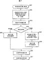
Figure 11 is used for the definite process flow diagram of disc-type that Japanese Patent Application Publication No.H07-029350 describes.Power connection, or new building inserts and is installed in the spindle motor that is used for rotating disc.And when carrying out comprising that about this dish individual layer still is the disc-type of multilayer when determining (S401), the opening and closing state of identifying hole that detects box is to determine that dish is single-layered disk or multilayer disc (S402).When definite this dish is single-layered disk, reproduction light quantity is adjusted to the reproduction light quantity (first light quantity) that is used for single-layered disk and reproduced above-mentioned preformat information (S403).
Then, executive logging operation or reproduction operation (S404).Recording operation or reproduction operation are turn-offed the semiconductor laser (S405) that is used as light source after finishing.Then, light source turn-offs, and perhaps dish is ejected (S406), thereby finishes processing.
On the other hand, when when step S402 determines that dish is multilayer disc, reproduction light quantity is adjusted into the reproduction light quantity (second light quantity) that is used for multilayer disc and reproduces preformat information (S407) as mentioned above.After this, executive logging operation or reproduction operation (S404) in a similar manner.When operation was finished, semiconductor laser turn-offed (S405).Then, power remove perhaps coils and is ejected, thereby finishes processing (S406).
In recent years, in order to realize each the reducing of size, thickness and weight of disc apparatus and recording medium, the dish itself that is not included in the box is used in expectation.This is one of inevitable development project in the exploitation of following compact disk equipment.Therefore, expect identifying hole different with Japanese Patent Application Publication No.H07-029350, that do not use box and determine that dish comprises that individual layer still is the method for multilayer.
Determine method as another kind of disc-type, for example, the method for a kind of detection by the peak value of the actuator for objective lenses focus signal that mobile object lens produce on the direction perpendicular to panel surface arranged.In this method, when detecting signal peak, determine that this dish comprises individual layer.When detecting two peak values, it is two-layer to determine that this dish comprises.
Yet, if be used under the reproduction light quantity of multilayer disc (second light quantity) single-layered disk execution disc-type being determined that generation is reproduced and worsened as mentioned above.Depend on the position that is focused on, cause the destruction of the user profile that write down easily.
Summary of the invention
An object of the present invention is to provide a kind of optical information recorder and reproducer, this equipment can determine that recording medium is individual layer recording medium or multilayer recording medium, and do not cause reproduce worsening service recorder medium and recording medium is included in the box only simultaneously.
Particularly, this optical information recorder and reproducer comprise: light source; Object lens are used for the laser focusing from light source is write down or information regeneration with execution information on optical record medium, and this optical record medium has the signal recording surface of single or multiple lift; Determine device, be used for the number of plies of the signal recording surface of definite optical record medium; And controller, be used to adjust the amount that shines the laser on the optical record medium, and in this optical information recorder and reproducer, when definite device is determined the number of plies, in response to the instruction that comes self-controller, the amount that shines the laser on the optical record medium is set to the amount that is used to reproduce from the information of this optical record medium.
Description of drawings
Fig. 1 shows the block diagram of the first embodiment of the present invention;
Fig. 2 shows the topology view according to the optical system of the light pick-up of the first embodiment of the present invention;
Fig. 3 shows the process flow diagram of determining operation according to the disc-type of the first embodiment of the present invention;
Fig. 4 shows the key diagram of carrying out the definite method of disc-type based on the peak value of reflection light quantity;
Fig. 5 shows the block diagram of the second embodiment of the present invention;
Fig. 6 shows the topology view of the optical system of light pick-up according to a second embodiment of the present invention;
Fig. 7 shows the process flow diagram of the definite operation of disc-type according to a second embodiment of the present invention;
Fig. 8 shows the block diagram of the third embodiment of the present invention;
Fig. 9 shows the topology view of optical system of the light pick-up of a third embodiment in accordance with the invention;
Figure 10 shows the process flow diagram of the definite operation of disc-type of a third embodiment in accordance with the invention; And
Figure 11 shows the process flow diagram that conventional disc-type is determined operation.
Embodiment
After this, will be described in detail with reference to the attached drawings enforcement optimal mode of the present invention.
(first embodiment)
Fig. 1 shows the block diagram according to the compact disk equipment of the first embodiment of the present invention.In Fig. 1, reference number 1 expression is as the CD of optical record medium.Compact disk equipment comprises the spindle motor 2 that is used to rotate the CD of installing on it 1, and the spindle motor driver 3 that is used to rotate drives spindle motor 2.
This compact disk equipment further comprise be used for to or from the optical pickup apparatus 6 of CD 1 record or information reproduction.Optical pickup apparatus 6 comprises the semiconductor laser 7 as light source, be used for will from the beam convergence of semiconductor laser 7 on the recording surface of CD 1 to form the object lens 4 of hot spot, actuator for objective lenses 5, be used to control the laser driver 24 of the light quantity of semiconductor laser 7, other optical element (not shown), and be used to detect catoptrical sensor on the CD 1.Actuator for objective lenses 5 in the following manner, two ground drive object lens 4 on perpendicular to the direction of panel surface and on the horizontal direction, in this mode, make light beam focus on and follow CD 1 (focusing on the recording surface simultaneously with plane deflection (runout), after this be called " Fo "), and make light beam follow to be arranged on the road in the CD 1 (to be followed the tracks of; After this be called " Tr ")
This compact disk equipment further comprises the optical pickup apparatus driver 8 that is used to control actuator for objective lenses 5, laser driver 24 etc., be used for search motor 9 at the radial transfer optical pickup apparatus 6 of CD 1, be used to control the search motor driver 10 of searching motor 9, and be used to carry out the following definite disc-type of disc-type that will describe and determine device 27 about the recording layer of CD 1.
This compact disk equipment further comprises the controller 11 that for example is made of CPU and storer.Controller 11 is carried out servo/RF and is handled, such as the processing of each driver of control and from the processing that is arranged on the signal of sensor in the optical pickup apparatus 6.In addition, controller 11 control overall optical disc apparatus 12 are with as being used for the central apparatus that each sequence is controlled.Compact disk equipment 12 is made up of above-mentioned component parts.In this embodiment, the laser driver 24 that is used to adjust the output power of semiconductor laser 7 is adjusted circuit corresponding to light quantity.
Fig. 2 shows the optical system of optical pickup apparatus 6.Be separated into main beam and two beamlets from the light beam of semiconductor laser 7 irradiations by grating 22.Beamlet is used for producing the servosignal that is used for differential push-pull (DPP).
The part of the light beam by grating 22 reflects on polarization beam splitter 13, and converges to monitor PD 15 by convergent lens 14.The output of monitor PD 15 is used for controlling the irradiation power of semiconductor laser 7.
Light beam by polarization beam splitter 13 is converted to parallel beam by λ/4 plates 23 and by collimation lens 16.Then, this light beam is imaged on the information recording surface of CD 1 by the transparent substrates of object lens 4 by CD 1.On polarization beam splitter 13, reflect by object lens 4, collimation lens 16 and λ/4 plates 23 in beam reflected on the CD 1.Beam reflected converges on the servo PD 18 of RF by sensor leads 17.Based on the output of the servo PD 18 of RF and acquired information signal and servosignal.
Then, the operation of compact disk equipment 12 will be described in detail.At first, light picker driver 8, search motor driver 10 and spindle motor driver 3 carry out integral body control by controller 11.Then, spindle motor driver 3 makes spindle motor 2 rotate with required speed of rotation.Therefore, the CD 1 that is installed on the spindle motor 2 together rotates with it.
Search motor 9 as stepper motor drives by searching motor driver 10, optical pickup apparatus 6 is sent to the optional position in the radial direction of CD 1.Laser driver 24 is by optical pickup apparatus driver 8 Be Controlled, with the laser of control from the semiconductor laser 7 of optical pickup apparatus 6.Laser is converged to by object lens 4 on the recording surface of CD 1, with the information of recorded information or reproducing recorded.
At this moment, as mentioned above, object lens 4 are followed the tracks of the road that is provided with in the recording surface of CD 1.Therefore, the drive current (electric current that flows on the Fo direction is the Fo electric current, and the electric current that flows on the Tr direction is the Tr electric current) that offers actuator for objective lenses 5 is controlled based on Fo error signal and Tr error signal by optical pickup apparatus driver 8, as described later.Notice that the Fo error signal obtains corresponding to the relative distance on the vertical direction between object lens 4 and the CD 1, and becomes 0 in focus state.This signal obtains by for example astigmatism method.
On the other hand, the Tr error signal is that the relative position on the parallel direction that forms corresponding to the road that is provided with in the recording surface of CD 1 and on it between panel surface of hot spot obtains, and becomes 0 under the situation at the center that hot spot is located substantially on.For example, this signal obtains by push-pull method or differential push-pull method.The method that produces Fo error signal and Tr error signal is known, thereby omits its explanation at this.In the present invention, can certainly use method except astigmatism method and differential push-pull method.
Fig. 3 shows the illustrative flow according to the operation of the compact disk equipment of this embodiment.At first, determine that at needs CD 1 comprises that individual layer still is (S101) under the disc-type of the multilayer situation about determining, under the situation such as the power connection of compact disk equipment, perhaps CD 1 is installed under the situation on the spindle motor 2, and semiconductor laser 7 responses come the instruction of self-controller 11 and connect by laser driver 24.Then, the output of control semiconductor laser 7, make become to be used for single-layered disk from the quantitative change of object lens 4 emitting lasers reproduction light quantity (first light quantity) (S102).With laser radiation CD 1.As mentioned above, first light quantity is the light quantity that is used to reproduce from the information of single-layered disk.
Then, disc-type determines that the recording layer of device 27 definite CD 1 under the control of controller 11 is to constitute (S103) by individual layer or multilayer (for example two-layer).The back will be described and determine that recording layer is the method that is made of individual layer or multilayer.When definite CD 1 is single-layered disk, executive logging operation or reproduction operation, and do not change reproduction light quantity (S104).
At this moment, as mentioned before, reproduce the information of preformat from CD 1 with first light quantity, and based on the information and executing record of this preformat or reproduce.At the moment of record, setting recording power.After record or reproduction were finished, laser driver 24 turn-offed semiconductor lasers 7 (S105).Then, power remove, or CD 1 ejection (S106), thus finish processing.
On the other hand, when definite CD 1 is dual layer discs, under the control of controller 11, control the output of semiconductor laser 7 by laser driver 24.Therefore, will be adjusted into the reproduction light quantity that is used for dual layer discs (second light quantity is approximately equal to two times of first light quantity) from the amount of the light of object lens 4 outgoing (S107), and executive logging or reproduction (S108).In this case, reproduce preformat information from CD 1 with second light quantity, and based on this preformat information and executing record or reproduction.At the moment of record, setting recording power.After record or reproduction were finished, semiconductor laser 7 turn-offed (S105).Then, power remove, or CD 1 ejection (S106), thus finish processing.As mentioned above, second light quantity is the light quantity that is used to reproduce from the information of multilayer disc.
Then, determine method with describing in detail according to the disc-type that is used for CD 1 of this embodiment.For example, when object lens 4 move up and down on the Fo direction, and the light quantity of reflection on CD 1 is when being detected by the servo PD 18 of RF, obtains to focus on the signal that every layer of its peak value when going up becomes maximum when light.Therefore, can determine disc-type based on the peak value number of indication focus state.
Therefore, as shown in Figure 4, set any threshold x.Have only when the signal peak that detects above threshold value x (representing), determine that CD 1 is a single-layered disk by solid line shown in Figure 4.When peak value is lower than threshold value x because light quantity is inadequate,, can determine that CD 1 is a dual layer discs maybe when detecting two peak values when (representing) by dotted line shown in Figure 4.In this case, light quantity can be adjusted into second light quantity, determine to carry out disc-type once more.
As mentioned above,,, can determine that CD 1 is single-layered disk or multilayer disc, worsen and do not cause reproducing when to be used to reproduce when carrying out disc-type and determine from first light quantity of the information of single-layered disk even under the situation of blank disc.
(second embodiment)
Fig. 5 shows the block diagram of compact disk equipment according to a second embodiment of the present invention.Fig. 6 shows the structural drawing of the optical system of the optical pickup apparatus 6 that is used for this compact disk equipment.In Fig. 5 and 6, for identical reference number being set, thereby omit its explanation with the identical part shown in Fig. 1 and 2 of first embodiment.
Identical among basic structure and basic operation and first embodiment.In this embodiment, by using the light quantity relaxation equipment of describing among the Japanese Patent Application Publication No.2004-199755 (polarization beam splitter and liquid crystal cell) that light quantity is adjusted into first light quantity or second light quantity.Quantity-of-light adjusting method is described in the open No.2004-199755 of Jap.P., therefore omits its explanation at this.
In Fig. 5 and 6, reference number 19 expression liquid crystal cells, and the liquid crystal cell driver of 25 expression control liquid crystal cells 19.Though not shown in Fig. 5, the laser driver 24 shown in Fig. 1 is included in the optical pickup apparatus driver 8.In this embodiment, polarization beam splitter 13, liquid crystal cell 19 and liquid crystal cell driver 25 are formed light quantity adjustment circuit.
The situation that is in the power remove state with liquid crystal cell 19 is compared, and in the power connection state, the molecules align state of liquid crystal cell 19 changes.Decay about 50% from the light quantity of object lens 4 outgoing by the combination of liquid crystal cell 19 and polarization beam splitter 13.Therefore, in this embodiment, the information regeneration output light quantity of semiconductor laser 7 constantly is set at the reproduction light quantity that is used for multilayer disc consistently, and the power connection/off state of control liquid crystal cell 19.Thereby, be adjusted to first light quantity or second light quantity from the light quantity of object lens 4 outgoing.
Fig. 7 shows the process flow diagram of determining operation according to the disc-type that is used for CD of this embodiment.When the power connection of compact disk equipment or when CD 1 inserts wherein (S201), controller 11 control liquid crystal cell drivers 25.Then, make liquid crystal cell 19 enter the power connection state, become above-mentioned first light quantity (S202) from the light quantity of object lens 4 outgoing to change the molecules align state of liquid crystal cell 19, to make.
Then, semiconductor laser 7 is connected (S203), and disc-type determines that device 27 is as carrying out disc-type definite (S204) with first light quantity among first embodiment.When disc-type determines that device 27 determines that CD 1 is single-layered disk, do not carry out any change ground executive logging or reproduction (S205).In this case, reproduce preformat information from CD 1 with first light quantity, and based on this preformat information and executing record or reproduction.At record constantly, setting recording power.After record or reproduction were finished, semiconductor laser 7 turn-offed (S206).Then, power remove or CD 1 eject (S207), thereby finish processing.
On the other hand, when definite CD 1 is multilayer disc (being dual layer discs among this embodiment), by controller 11 control liquid crystal cell drivers 25.Make liquid crystal cell 19 enter the power remove state changing its molecules align state, thereby reproduction light quantity is adjusted into second light quantity (S208).Then, executive logging or reproduction (S209).In this case, reproduce preformat information from CD 1 with second light quantity, and based on this preformat information and executing record or reproduction.At record constantly, setting recording power.After record or reproduction were finished, semiconductor laser 7 turn-offed (S206).Then, power remove or CD 1 eject (S207), thereby finish processing.
As mentioned above, when polarization beam splitter 13 and liquid crystal cell 19 are used for the light quantity relaxation equipment, compare with the situation of first embodiment, the high power state of semiconductor laser 7 can be kept continuously.Therefore, may prevent that signal quality as the semiconductor laser 7 of light source is owing to quantizing noise worsens.This is especially effective for using the compact disk equipment such as the blue laser of Blu-ray Disc equipment, and in Blu-ray Disc equipment, various pressure margin and DVD equipment etc. are compared all very tight.
The present invention is not limited only to the structure of this embodiment.For example, when using polarization holograms to replace polarization beam splitter 13, and when it was combined with liquid crystal cell, light quantity can be attenuated as in the above-mentioned situation.Liquid crystal cell 19 can be arranged between grating 22 and the polarization beam splitter 13.
(the 3rd embodiment)
Fig. 8 shows the block diagram of the compact disk equipment of a third embodiment in accordance with the invention.Fig. 9 shows the structural drawing of the optical system of the optical pickup apparatus 6 that is used for compact disk equipment.Basic structure and basic operation are identical with first and second embodiment's.In Fig. 8 and 9, for having identical reference number is set, thereby the descriptions thereof are omitted at this with the part of the first and second embodiment identical functions.In this embodiment, by using the light quantity relaxation equipment of describing among the Japanese Patent Application Publication No.2003-257072 that light quantity is adjusted into first light quantity or second light quantity.
In Fig. 8 and 9, reference number 20 expressions are used as the light filter of light quantity relaxation equipment.Drive light filter 20 by the light filter drive motor 26 that is used as stepper motor.Light filter drive motor 26 is driven by motor driver 21.Motor driver 21 is by 8 controls of optical pickup apparatus driver.Though not shown in Figure 8, the laser driver of describing among first embodiment 24 is included in the optical pickup apparatus driver 8.
Quantity-of-light adjusting method is described in the open No.2003-257072 of Jap.P., and therefore the descriptions thereof are omitted at this.In this embodiment, light filter drive motor 26 is driven by motor driver 21, and transmissivity is that 50% light filter 20 is inserted into optical axis or removes from optical axis, thereby adjusts light quantity.In other words, as in a second embodiment, be the reproduction light quantity (second light quantity) that is used for multilayer disc with the output fader control of semiconductor laser 7.Under the situation of single-layered disk, light filter 20 is set on the optical axis, with the decay light quantity, thereby reproduction light quantity is adjusted into first light quantity.Under the situation of multilayer disc, light filter 20 moves on arrow shown in Figure 9 " A " indicated direction, so that light filter 20 is removed from optical axis, thereby reproduction light quantity is adjusted into second light quantity.
Figure 10 shows the process flow diagram according to the operation of this embodiment.When the power connection of compact disk equipment or when CD 1 inserts wherein (S301), by controller 11 control motor drivers 21, and the driving of light filter 20 by light filter drive motor 26 is arranged on the optical axis.Therefore, the light quantity from object lens 4 outgoing is adjusted to first light quantity (S302).Then, connect semiconductor lasers 7 (S303), and determine that by disc-type device 27 carries out disc-type definite (S304) as among first and second embodiment on CD 1 by controller 11.
Result as disc-type is determined when CD 1 is single-layered disk, does not carry out any change ground executive logging or reproduction (S305).In this case, reproduce preformat information from CD 1 with first light quantity, and based on this preformat information and executing record or reproduction.At record constantly, setting recording power.After record or reproduction were finished, semiconductor laser 7 turn-offed (S306).Then, the power remove of compact disk equipment or CD 1 eject (S307), thereby finish processing.
On the other hand, when definite CD 1 is multilayer disc (being dual layer discs among this embodiment), by controller 11 control motor drivers 21, and light filter 20 is by the driving of light filter drive motor 26, and the direction that shifts out from optical axis at light filter (by arrow 66A shown in Figure 9 " indicated direction) mobile.Thereby reproduction light quantity is adjusted into second light quantity (S308).Then, executive logging or reproduction (S309).At this moment, reproduce preformat information from CD 1 with second light quantity, and based on this preformat information and executing record or reproduction.At record constantly, setting recording power.After record or reproduction were finished, semiconductor laser 7 turn-offed (S306).Then, the power remove of compact disk equipment or CD 1 eject (S307), thereby finish processing.
In this embodiment, can insert optical axis or be used as the light quantity relaxation equipment, make and compare, can reduce power consumption with the situation of second embodiment from the light filter that optical axis is removed.This is because when using liquid crystal cell 19, under the state of first light quantity, power offers liquid crystal cell 19 continuously, to keep the molecules align state of liquid crystal cell 19.
In this embodiment, for example, when using stepper motor, piston etc. that light filter 20 is inserted optical axises or when optical axis is removed, can keep the power remove state switching to first light quantity from second light quantity or switch to from first light quantity in time beyond the second light quantity time necessary, make cpable of lowering power consumption.
In the above-described embodiments, suppose that CD is a multilayer disc, more specifically, number of layers is two.Even under the situation of three layers or more multi-layered dish (medium), also can use the present invention.That is,, be used for the reproduction light quantity that disc-type determines and also can be set at first light quantity even under three layers or more multi-layered situation.
This application requires the right of priority of the Japanese patent application No.2005-048993 of application on February 24th, 2005, is incorporated herein this application as a reference.
Claims (5)
1. optical information recorder and reproducer comprise:
Light source;
Being used for will be from the laser focusing of the light source object lens with execution information record or information regeneration to the optical record medium, and described optical record medium has the signal recording surface of single or multiple lift;
Be used for determining definite device of the number of plies of the signal recording surface of optical record medium; And
Be used to adjust the controller that shines the amount of laser light on the optical record medium,
Wherein when definite device was determined the number of plies, in response to the instruction that comes self-controller, the amount of laser light that shines on the optical record medium was set to the light quantity that is used to reproduce from the information of the optical record medium with individual layer.
2. optical information recorder according to claim 1 and reproducer, the output power of wherein said controller control light source.
3. optical information recorder according to claim 1 and reproducer further are included in the light quantity relaxation equipment that is provided with on the light path between light source and the object lens,
Wherein this controller is controlled this light quantity relaxation equipment.
4. optical information recorder according to claim 3 and reproducer, wherein this light quantity relaxation equipment comprises liquid crystal cell, and this light quantity relaxation equipment is controlled by the switching between the power connection/off state of liquid crystal cell.
5. optical information recorder according to claim 3 and reproducer, wherein this light quantity relaxation equipment comprises light filter, and this light quantity relaxation equipment is removed from light path and controlled by light filter being inserted into light path neutralization.
Applications Claiming Priority (2)
| Application Number | Priority Date | Filing Date | Title |
|---|---|---|---|
| JP2005048993A JP2006236469A (en) | 2005-02-24 | 2005-02-24 | Optical information recording and reproducing medium |
| JP2005048993 | 2005-02-24 |
Publications (2)
| Publication Number | Publication Date |
|---|---|
| CN1825440A CN1825440A (en) | 2006-08-30 |
| CN100375997C true CN100375997C (en) | 2008-03-19 |
Family
ID=36912547
Family Applications (1)
| Application Number | Title | Priority Date | Filing Date |
|---|---|---|---|
| CNB2006100514458A Expired - Fee Related CN100375997C (en) | 2005-02-24 | 2006-02-24 | Optical information recording and reproducing apparatus |
Country Status (3)
| Country | Link |
|---|---|
| US (1) | US20060187786A1 (en) |
| JP (1) | JP2006236469A (en) |
| CN (1) | CN100375997C (en) |
Families Citing this family (9)
| Publication number | Priority date | Publication date | Assignee | Title |
|---|---|---|---|---|
| JP2007115319A (en) * | 2005-10-19 | 2007-05-10 | Canon Inc | Optical pickup device |
| US7680013B2 (en) * | 2005-11-29 | 2010-03-16 | Canon Kabushiki Kaisha | Optical information recording and reproducing apparatus |
| JP2007149253A (en) * | 2005-11-29 | 2007-06-14 | Canon Inc | Optical pickup device for holography |
| US7791986B2 (en) * | 2006-03-15 | 2010-09-07 | Canon Kabushiki Kaisha | Optical information recording/reproducing apparatus |
| JP2008033988A (en) * | 2006-07-26 | 2008-02-14 | Canon Inc | Information recording and reproducing device, and optical pickup |
| US7933182B2 (en) * | 2006-12-13 | 2011-04-26 | Canon Kabushiki Kaisha | Optical information recording and reproducing apparatus that sets a movable range of an objective lens based on the type of recording medium |
| JP2010118113A (en) * | 2008-11-13 | 2010-05-27 | Sony Corp | Disk driving device and disk discrimination method |
| JP2011192378A (en) * | 2010-02-19 | 2011-09-29 | Panasonic Corp | Optical disk device, and method of reproducing optical disk |
| WO2012008036A1 (en) * | 2010-07-15 | 2012-01-19 | パイオニアデジタルデザインアンドマニュファクチャリング株式会社 | Method and device for recording/reproducing information, and information reproducing device |
Citations (3)
| Publication number | Priority date | Publication date | Assignee | Title |
|---|---|---|---|---|
| US20020150017A1 (en) * | 2001-04-13 | 2002-10-17 | Kazuhiko Ono | Disc discriminating method and information reproducing apparatus using thereof |
| US20030012106A1 (en) * | 2001-07-10 | 2003-01-16 | Toshikazu Kobayashi | Recording layer determination apparatus for determining whether recording layer of recording medium is single-layer of multi-layer |
| US20030086347A1 (en) * | 2001-10-19 | 2003-05-08 | Toshikazu Kobayashi | Method for determining type of recording media |
Family Cites Families (7)
| Publication number | Priority date | Publication date | Assignee | Title |
|---|---|---|---|---|
| JP3719075B2 (en) * | 1999-12-13 | 2005-11-24 | 松下電器産業株式会社 | Optical disk device |
| US6940794B2 (en) * | 2001-08-03 | 2005-09-06 | Matsushita Electric Industrial Co., Ltd. | Information recording/reproducing apparatus that determines the number of recording layers of an information recording medium |
| US6909673B2 (en) * | 2002-02-22 | 2005-06-21 | Canon Kabushiki Kaisha | Magneto-optical recording apparatus having a magnetic head with a regulating member |
| JP2004102696A (en) * | 2002-09-10 | 2004-04-02 | Canon Inc | Information recording/reproducing apparatus and information recording/reproducing system |
| JP4040564B2 (en) * | 2003-10-14 | 2008-01-30 | キヤノン株式会社 | Disk-shaped recording medium alignment device |
| KR100990251B1 (en) * | 2003-12-23 | 2010-10-26 | 엘지디스플레이 주식회사 | Laser optical system including filter changing laser beam profile |
| JP2007115319A (en) * | 2005-10-19 | 2007-05-10 | Canon Inc | Optical pickup device |
-
2005
- 2005-02-24 JP JP2005048993A patent/JP2006236469A/en active Pending
-
2006
- 2006-02-01 US US11/344,240 patent/US20060187786A1/en not_active Abandoned
- 2006-02-24 CN CNB2006100514458A patent/CN100375997C/en not_active Expired - Fee Related
Patent Citations (3)
| Publication number | Priority date | Publication date | Assignee | Title |
|---|---|---|---|---|
| US20020150017A1 (en) * | 2001-04-13 | 2002-10-17 | Kazuhiko Ono | Disc discriminating method and information reproducing apparatus using thereof |
| US20030012106A1 (en) * | 2001-07-10 | 2003-01-16 | Toshikazu Kobayashi | Recording layer determination apparatus for determining whether recording layer of recording medium is single-layer of multi-layer |
| US20030086347A1 (en) * | 2001-10-19 | 2003-05-08 | Toshikazu Kobayashi | Method for determining type of recording media |
Also Published As
| Publication number | Publication date |
|---|---|
| JP2006236469A (en) | 2006-09-07 |
| CN1825440A (en) | 2006-08-30 |
| US20060187786A1 (en) | 2006-08-24 |
Similar Documents
| Publication | Publication Date | Title |
|---|---|---|
| CN100375997C (en) | Optical information recording and reproducing apparatus | |
| US7031233B2 (en) | Optical recording/reproduction device and focal point control method | |
| KR20060000742A (en) | Optical pickup and apparatus and method for assembling lenses | |
| US20110242948A1 (en) | Optical disc device and optical disc | |
| KR101058859B1 (en) | Optical pickup and recording and / or reproducing apparatus using the same | |
| CN100382172C (en) | Optical disc device, optical pickup control method and optical disc discriminating method | |
| CN101231856A (en) | Optical pickup device and optical information processor | |
| CN100397509C (en) | Optical pickup and optical disk apparatus | |
| KR20100076784A (en) | Aspheric lens and optical pickup employing the same as objective lens | |
| EP1496505A2 (en) | Optical pickup and optical recording and/or reproducing apparatus | |
| US7924682B2 (en) | Unit to remove crosstalk in multi-layered disk, optical pickup including the unit, and optical recording and/or reproducing apparatus including the optical pickup | |
| CN102479519B (en) | Information recording method, information regeneration method, and optical disc device | |
| JPH10106023A (en) | Recording/reproducing optical pickup for compatibility of disks with different thickness | |
| EP2118899A1 (en) | Compatible optical pickup and optical information storage medium system employing the same | |
| KR20000053390A (en) | Optical pickup, and optical recording/reproducing apparatus using same | |
| CN101501767B (en) | Optical information recorder/reproducer, optical information recording/reproducing method and control circuit | |
| KR20060105233A (en) | Hybrid disc and recording and/or reproducing apparatus and method for the same | |
| EP1376553B1 (en) | Recording apparatus and method for improving overwrite characteristics | |
| KR20080020901A (en) | An optical pick-up apparatus | |
| JPH09185839A (en) | Optical recording or optical reproducing device | |
| CN100362580C (en) | Optical head device, optical recording device, and optical recording method | |
| EP1959440A1 (en) | Optical pick-up with stray-light filtering element | |
| CN100407305C (en) | Optical pickup apparatus | |
| KR101106646B1 (en) | Optical pick-up and disc apparatus having the same | |
| KR100265734B1 (en) | Compatible optical pickup apparatus |
Legal Events
| Date | Code | Title | Description |
|---|---|---|---|
| C06 | Publication | ||
| PB01 | Publication | ||
| C10 | Entry into substantive examination | ||
| SE01 | Entry into force of request for substantive examination | ||
| C14 | Grant of patent or utility model | ||
| GR01 | Patent grant | ||
| C17 | Cessation of patent right | ||
| CF01 | Termination of patent right due to non-payment of annual fee |
Granted publication date: 20080319 Termination date: 20100224 |