CN100368950C - Method and system for controlling a machine tool by directly transmitting machining data - Google Patents
Method and system for controlling a machine tool by directly transmitting machining data Download PDFInfo
- Publication number
- CN100368950C CN100368950C CNB018096743A CN01809674A CN100368950C CN 100368950 C CN100368950 C CN 100368950C CN B018096743 A CNB018096743 A CN B018096743A CN 01809674 A CN01809674 A CN 01809674A CN 100368950 C CN100368950 C CN 100368950C
- Authority
- CN
- China
- Prior art keywords
- moving line
- line data
- machine
- motion
- processor
- Prior art date
- Legal status (The legal status is an assumption and is not a legal conclusion. Google has not performed a legal analysis and makes no representation as to the accuracy of the status listed.)
- Expired - Fee Related
Links
Images


Classifications
-
- G—PHYSICS
- G05—CONTROLLING; REGULATING
- G05B—CONTROL OR REGULATING SYSTEMS IN GENERAL; FUNCTIONAL ELEMENTS OF SUCH SYSTEMS; MONITORING OR TESTING ARRANGEMENTS FOR SUCH SYSTEMS OR ELEMENTS
- G05B19/00—Programme-control systems
- G05B19/02—Programme-control systems electric
- G05B19/418—Total factory control, i.e. centrally controlling a plurality of machines, e.g. direct or distributed numerical control [DNC], flexible manufacturing systems [FMS], integrated manufacturing systems [IMS] or computer integrated manufacturing [CIM]
-
- G—PHYSICS
- G05—CONTROLLING; REGULATING
- G05B—CONTROL OR REGULATING SYSTEMS IN GENERAL; FUNCTIONAL ELEMENTS OF SUCH SYSTEMS; MONITORING OR TESTING ARRANGEMENTS FOR SUCH SYSTEMS OR ELEMENTS
- G05B19/00—Programme-control systems
- G05B19/02—Programme-control systems electric
- G05B19/18—Numerical control [NC], i.e. automatically operating machines, in particular machine tools, e.g. in a manufacturing environment, so as to execute positioning, movement or co-ordinated operations by means of programme data in numerical form
- G05B19/4097—Numerical control [NC], i.e. automatically operating machines, in particular machine tools, e.g. in a manufacturing environment, so as to execute positioning, movement or co-ordinated operations by means of programme data in numerical form characterised by using design data to control NC machines, e.g. CAD/CAM
-
- G—PHYSICS
- G05—CONTROLLING; REGULATING
- G05B—CONTROL OR REGULATING SYSTEMS IN GENERAL; FUNCTIONAL ELEMENTS OF SUCH SYSTEMS; MONITORING OR TESTING ARRANGEMENTS FOR SUCH SYSTEMS OR ELEMENTS
- G05B2219/00—Program-control systems
- G05B2219/30—Nc systems
- G05B2219/35—Nc in input of data, input till input file format
- G05B2219/35002—Parametric machine control, direct control from cad data, no nc data
-
- G—PHYSICS
- G05—CONTROLLING; REGULATING
- G05B—CONTROL OR REGULATING SYSTEMS IN GENERAL; FUNCTIONAL ELEMENTS OF SUCH SYSTEMS; MONITORING OR TESTING ARRANGEMENTS FOR SUCH SYSTEMS OR ELEMENTS
- G05B2219/00—Program-control systems
- G05B2219/30—Nc systems
- G05B2219/35—Nc in input of data, input till input file format
- G05B2219/35097—Generation of cutter path, offset curve
-
- G—PHYSICS
- G05—CONTROLLING; REGULATING
- G05B—CONTROL OR REGULATING SYSTEMS IN GENERAL; FUNCTIONAL ELEMENTS OF SUCH SYSTEMS; MONITORING OR TESTING ARRANGEMENTS FOR SUCH SYSTEMS OR ELEMENTS
- G05B2219/00—Program-control systems
- G05B2219/30—Nc systems
- G05B2219/36—Nc in input of data, input key till input tape
- G05B2219/36266—Tool path editor, for offset, multi-passes
-
- Y—GENERAL TAGGING OF NEW TECHNOLOGICAL DEVELOPMENTS; GENERAL TAGGING OF CROSS-SECTIONAL TECHNOLOGIES SPANNING OVER SEVERAL SECTIONS OF THE IPC; TECHNICAL SUBJECTS COVERED BY FORMER USPC CROSS-REFERENCE ART COLLECTIONS [XRACs] AND DIGESTS
- Y02—TECHNOLOGIES OR APPLICATIONS FOR MITIGATION OR ADAPTATION AGAINST CLIMATE CHANGE
- Y02P—CLIMATE CHANGE MITIGATION TECHNOLOGIES IN THE PRODUCTION OR PROCESSING OF GOODS
- Y02P90/00—Enabling technologies with a potential contribution to greenhouse gas [GHG] emissions mitigation
- Y02P90/02—Total factory control, e.g. smart factories, flexible manufacturing systems [FMS] or integrated manufacturing systems [IMS]
Landscapes
- Engineering & Computer Science (AREA)
- Manufacturing & Machinery (AREA)
- Physics & Mathematics (AREA)
- General Physics & Mathematics (AREA)
- Automation & Control Theory (AREA)
- Human Computer Interaction (AREA)
- General Engineering & Computer Science (AREA)
- Quality & Reliability (AREA)
- Numerical Control (AREA)
- Multi-Process Working Machines And Systems (AREA)
Abstract
Method and system for a direct transmission of motion path data (310) from a generating system (204) to a control system (205) for use in controlling a servo-driven machine. For example, a machine tool for machining stock material, and the data generating system includes a computer-aided-design software package (301). Tool paths for directing the tool members of the machine tool can be extracted from a design file opened by the CAD software through the operation interface of the CAD software (302). Alternatively, the design file can be used to specify motion paths rather than end product geometry. The CAD interpreter application extracts the motion path data from the design file, eliminating the need to translate the data into another or intermediate form for controlling the machine tool.
Description
Technical field
The present invention relates to digitally to connect the field of the machine of robot, lathe or other servo driving, these equipment have the system of the data of the machine that is provided for controlling servo driving.The invention still further relates to the field of numerically controlled or computer-controlled lathe by suitable material production equipment part, this manufacturing is the technical requirement roughing and/or the finishing original material sheet of the part that basis will be manufactured.More particularly, the present invention relates to a kind of by the process data of the workpiece that will make of definition is directly passed to the new example that machine controller is controlled operation of machine tool from the CAD/CAM application program.
Background technology
Have many machineries to have movable part in modern industry, these movable parts are driven by servomotor.These machineries comprise industrial robot, coordinate measuring machine, lathe or the like.The machinery of these classifications is generically and collectively referred to as " machinery of servo driving. " here
Usually, main system provides data to servo controller, and servo controller control servomotor suitably turns round and the parts of shift servo machine driven.Lathe is the outstanding example of the machinery of this servo operation, The present invention be more particularly directed to this lathe.
When manufactured, being exclusively used in these mechanical parts must be by suitable material customization when these machineries are developed at first or on limited basis.This finishes by " processing " process usually, this be one as required with one or mechanically cutting of a block of material, grinding, boring and finishing to produce the process of needed part.The machine that is used for starting material are transformed into the regulation part is called as " lathe " after this.Modern lathe high complexityization also is accurately controlled, so that according to the technical requirement manufactured parts of precision.Most of this modern machines are by the computer control of handling the precise figures instruction that defines the part that will make.
First numerically-controlled machine is the 3 axis milling machines of building nineteen fifty-two.Used numeral the moving of regulation milling head in one the three axis system so that the part that processing needs.Yet,, mechanically set described lathe with hand according to the standard numeral along with the development of processing.Along with development of electronic technology afterwards, " numerical control " lathe is equipped with sophisticated electronics more and more to process processing automatically.Nowadays, numerically-controlled machine comprises computer processor and electronic memory module (RAM and ROM).Thereby lathe of today is the lathe of computer control, is called " cnc machine tool ".
Early stage computer-controlled machine tool is accepted input from punched tape.Be recorded in instruction on these paper tapes and be I/O (" I/O ") instruction (for example opening/closing spindle or cooling medium are provided with default inlet amount and speed, or the like .) and movement instruction (for example, the mode with straight line or circle moves on to some x y z positions).The language of writing these instructions is called as M﹠amp; The G sign indicating number.Can think M﹠amp; The G sign indicating number is similar to the assembly language that is used for PC; It is the programming that is used for the floor level of lathe, and is generally accepted by all lathes, and irrelevant with structure or model.Even produced first numerically controlled machine before about five more than ten years, but we still use this identical M﹠amp that only has than light maintenance; G sign indicating number language comes lathe is programmed.
Passed through 50 years, many companies are building desirable machine tool controller always hardy.These controllers comprise the hardware element of routine and the operating system that hyperspecialization has nothing in common with each other.Having many in these controllers has been proprietary closed system.May just occur though be used for the open architecture of the hardware of these control system, lathe of today uses the technology that history decades has been arranged to a great extent.Proprietary control continues to be in lathe hardware control technology, and can only pass through M﹠amp to the programming of machine; G sign indicating number environment is carried out.
M﹠amp; G code uses literal in a single file or program, or independent instruction, and module, perhaps goes.Read all instructions in the delegation, and carry out all instructions simultaneously.In order to generate M﹠amp; The G program is necessary for all cutter paths and calculates all geometric configuratioies, for example, and the point of a knife of lathe passes through when the required part of processing line segment and camber line.Go out motion and I/O instruction from this geometry computations.These instructions must be write as M﹠amp then; The G sign indicating number, described code must be input in the controller.At first, must be with hand with M﹠amp; The G sign indicating number is input to described controller, perhaps punches on mylar or paper tape, subsequently mylar or paper tape is delivered in the reader on the controller.Even now, in order to write the M﹠amp of a processed complex part; The G program also is a long slowly and dull task.
At the end of the fifties and the beginning of the sixties, many new programming languages have more flexibly appearred.Automatically programmed tools (" APT ") is exactly to occur at first in these newspeaks.Use APT, the slip-stick artist can stipulate the geometric configuration of lathe, the machined parameters of the I/O of the geometric configuration of point of a knife and control lathe.Yet, because the specificity and the inconsistency of existing machine system must finally be translated into more basic M﹠amp to the instruction that generates with APT; The G sign indicating number.The APT application program is carried out according to the instruction in the APT program and is calculated to generate a tool position (" CL ") file.The CL file is the ASCII character file, and this document comprises the geometric configuration in the path that the point of a knife of lathe must pass through in process.Use a kind of program that is called as post processor that this CL file translation is become M﹠amp then; The G sign indicating number.
In the sixties and the seventies, along with computing machine becomes cheaper and more powerful, more the design of multimachine tool adopts computer-aided design (CAD) (" CAD ") program to carry out.Computer-aided manufacturing (" CAM ") program allows the user to use the geometric configuration of stipulating in the CAD program to prepare out to be used for cutter path that lathe is programmed.It is generally acknowledged CAD, CAM and CAD/CAM program are the software packages that belongs to general classes at this, are commonly referred to " design application ".Form with CL or APT file is exported the cutter path that is defined by the CAM application program, it must be translated into M﹠amp before sending this document to machine controller; G code.These practices remain the standard of nowadays using.
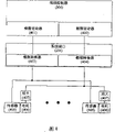
The canonical process that uses the CAD/CAM application program that lathe is programmed shown in Fig. 1.As shown in fig. 1, the CAD/CAM application program goes up operation at workstation (100).Use the CAD/CAM application program, generates a CAD/CAM file (101), this file (101) has been stipulated the geometric configuration of lathe and part that will be manufactured.Comprise the file of the design data that generates by CAD/CAM or similar software package, be referred to as " design document " here such as file (101).
CAD/CAM application program or perhaps be that a kind of independently application program uses the CAD/CAM file to calculate to be used for the lathe end in the cutter positioning of whole process data and generate CL file (102) then.CL file (102) is an ASCII character file.CL file (102) can be interpreted into M﹠amp then; G sign indicating number (103), M﹠amp; The G sign indicating number also is an ASCII character file.Translate into M﹠amp from CL file (102); G sign indicating number (103) is carried out by a post processor usually.Then with M﹠amp; G sign indicating number (103) is transferred to described machine tool controller (104), and this machine tool controller uses this sign indicating number to control described lathe (not shown) in the process of processing regulation part.
By the output of CL file (102) from CAD/CAM software, each CL file all with source CAD/CAM file (101) folk prescription to being associated.Thereby any modification to source CAD/CAM file (101) can not be reflected in the CL file (102) of an output, needs to produce new " son " ASCII CL file (102), revises always from the source file to the son file.Equally, may prepare M﹠amp by the machinist; G sign indicating number file and modification that son file (102) is carried out also can or not corrected the generation effect to the modification of source design document (101).
As the evolution of design, this unidirectional streams data requires to preserve all relevant existing files and the outmoded file of deletion, and this can bring a lot of problems.Therefore, need a kind of method and system that can control lathe better in the art, help revising, upgrading and manage the control documents that offers machine tool controller.
Even other problem is exactly " standard " M﹠amp between machine tool controller; Also there is difference in the G sign indicating number.In fact, M﹠amp; The G sign indicating number is inconsistent between a kind of lathe and another lathe.All carrying out M﹠amp always; The standardization effort of G sign indicating number, but never success.These problems are mainly brought by the following fact, that is, and and M﹠amp; The G standard does not possess the dirigibility of implementing many functions, and these functions are that senior machining tool can be realized.The manufacturer of these senior lathes has to use distinctive new instruction to continue existing standard, so that new process technology is added on the code framework, if so do not do, this code framework is not just supported these technology.
For example, the machine tool controller in many modern times can make the real non-homogeneous B spline curve of machine tooling (" NURBS ").Even it is not M﹠amp; The part of G code standard, these controllers are with non-standard M﹠amp; G code is identified as the code that is used for NURBS.
Even claim based on standard M﹠amp; G sign indicating number, its effect are DLL (dynamic link library) and language along with machine builder and model and change.Therefore, this area need a kind of avoid different make and the lathe of model between inconsistent M﹠amp; The method and system of the problem of G sign indicating number version.
At CL file and M﹠amp; In the G sign indicating number, geometric configuration is expressed as the cutter top by so that make the series of points of this geometric configuration.These points define the route of cutter.This route is made up of some straight-line segments, circle or spiral camber line.Promptly not that straight line is not again that circular route is approximately discrete point or little line segment.Moulding used in consumer products more and more with surface free form.CAD dealer moulds at their software and has obtained significant progress aspect complex curve, surface and the entity, but the instrument that is used to make them and technology also with use decades ago the same.
A composite surface can be represented by single equation in the CAD program, still may need to be expressed as thousands of line segments in the instruction that offers machine tool controller, so that obtain required degree of accuracy.When the traditional data stream that uses shown in Fig. 1, have no idea to avoid the loss on this degree of accuracy.
As mentioned above, there are some very expensive machine tool controllers to have and handle the NURBS ability of complicated route like this that resembles.This makes that this lathe can be faster and make composite surface more smoothly than using linear interpolation.Problem is that the technical requirement that will be used for required NURBS passes to machine tool controller.In order to communicate by letter with machine tool controller, the NURBS that stipulates in the CAD/CAM design document (perhaps using an independent equation for each curve) must be interpreted into M﹠amp; The line segment geometric configuration that the G sign indicating number uses.Machine tool controller can be with M﹠amp then; (also may stipulate) NURBS instruction that the line segment instruction translation of G sign indicating number becomes lathe to use by nurbs curve of series of points interpolation.This NURBS converts line segment to, turns back to real NURBS expression formula then and causes skimble-skamble precision reduction when the described NURBS of definition.
Therefore, this area also needs by the M﹠amp based on line segment; The intermediateness of G sign indicating number is avoided the system and method for unnecessary loss of significance, and this loss of significance is with will to be sent to the possible different NURBS expression formula of being used by senior machine tool controller by the NURBS expression formula that the CAD/CAM application program generates relevant.
Summary of the invention
An object of the present invention is to satisfy above-mentioned and other needs.Specifically, one object of the present invention just provides a kind of improved system and method, is used for the machine tool controller programming, so that process the part of regulation according to the data that produced by CAD/CAM or other design application.Another object of the present invention provides a kind of system and method, be used for machine tool controller programming, with avoid with manage reflection source design document in the relevant problem of a series of son files of evolution of Element Design.
Another object of the present invention provides a kind of system and method, is used for the machine tool controller programming, to avoid the M﹠amp owing to the various version of using in the lathe of not isostructure and model; The problem that the variation of G intersymbol high level instructions causes.A further object of the present invention provides a kind of system and method, be used for machine tool controller programming, avoiding the unnecessary loss of significance in the curve of regulation such as NURBS, this loss of significance with by for example M﹠amp; It is relevant that the line segment approximate value of using in the G sign indicating number is translated the expression formula of these curves.
Other purpose of the present invention, advantage and novel characteristic will be described in the instructions hereinafter, and those skilled in the art are by reading these materials or implementing the present invention and can understand these purposes, advantage and characteristic.Objects and advantages of the present invention can realize by the device of narrating in appending claims.
In order to realize purpose of the present invention, according to an aspect of the present invention, provide a kind of being used for that control system and the system that the machine of servo driving is connected are comprised: first processor, execution produces the moving line data and does not use M﹠amp; The design application of G sign indicating number; Second processor that is connected with described first processor, described second processor are carried out the motion control software of the described moving line data of described design application access from the described first processor; With the machine of wherein said motion control software according to described moving line Data Control servo driving, and described motion control software is OO, so that described motion control software is applicable to the machine connection that allows to make control system and different servo driving.
According to another aspect of the present invention, a kind of method that control system is connected with the machine of servo driving is provided, comprise: carry out the design application on the first processor, described design application produces the moving line data of the machine that is used for described servo driving, and described moving line data are not use M﹠amp; The G sign indicating number produces; Carry out the motion control software on second processor, described motion control software receives described moving line data with the identical form with described design application output; With the described moving line data of basis, control the machine of described servo driving with described motion control software from described design application.
According to a further aspect of the invention, provide a kind of with control system and the system that the machine of servo driving is connected, comprising: produce the device of the moving line data of the machine that is used for servo driving, described moving line data are not use M﹠amp; The G sign indicating number produces, and described device is used to produce the moving line data that comprise first processor; Be used to carry out the device of motion control software, this motion control software is to receive described moving line data with the identical form of being exported by the described device that produces described moving line data, and described device is used to carry out the motion control software that comprises second processor; With device according to the machine of the described servo driving of described moving line Data Control.
According to a further aspect of the invention, provide a kind of with control system and the system that the machine of servo driving is connected, comprising: carry out the first processor of design application, described design application produces the moving line data and does not use M﹠amp; The G sign indicating number; Second processor that is connected with described first processor, described second processor is carried out motion control software, and described motion control software receives described moving line data by the application programming interfaces of described motion control software from the described design application on the described first processor; With the machine of wherein said motion control software according to described moving line Data Control servo driving.
According to a further aspect of the invention, a kind of system that control system is connected with the machine of servo driving of being used for is provided, comprise: the first processor of carrying out design application, described design application produces the motion object that comprises the moving line data, and described moving line data are not use M﹠amp; The G sign indicating number produces, and the tool heads of the machine of described moving line data definition servo driving will be along its moving line that moves; Second processor that is connected with described first processor, described second processor execution receives described motion motion of objects Control Software from the described design application on the described first processor; With the machine of wherein said motion control software according to described moving line Data Control servo driving.
In a word, it is integrated to the invention provides the notion of traditional C AD workstation and machine tool controller.Machine tool controller preferably includes two processors, or two computing machines of a processor respectively are provided.First processor is carried out a kind of design application, that is, CAD, CAD/CAM or similar software package, this design application can be used for producing, checks or revises design document.Second processor is carried out the required software of the described lathe of control.
Can operate in software on second processor fully and realize the control of whole lathe.This software of several application programs or object that can comprise is commonly called " motion control software ".No longer need the part of other hardware structure as machine tool controller.
One or more cutter heads of moving line data regulation lathe must move to make a route or many routes of required product along it.If the application programming interfaces of design application (API), for example, the CAD/CAM software package, open and available, can directly from design document, extract the moving line data.Then, motion control software can use this cutter route data to drive lathe and make the product of stipulating.
In the situation of the API that can not obtain design application, design application, for example, the CAD/CAM software package can be given motion control software with the moving line data transfer, and this is a kind of API group of direct working motion Control Software.Then, motion control software can use the cutter route data to drive lathe and produce the product of regulation.
Preferably, with the form transmitting movement route data of C++ motion object, the position of one or more cutterheads of C++ motion object regulation lathe and any point in direction and any cutter route.Preferably, the motion object comprises three other objects: the speed of feed of the control of a machine element that is identified for servo driving and the speed object of speed; A velocity distribution generator object that is used in those moving line control rate conversions; With a route object that comprises the information that defines each moving line.
The moving line data of extracting from CAD system are generally in cartesian coordinate system.Therefore, motion control software is translated into suitable reference frame with Cartesian coordinate cutter route data, and the servo controller application program produces the servo-control signal of the servomotor that is used to drive lathe from this reference frame.
Description of drawings
Accompanying drawing shows the present invention, and is the part of instructions.These accompanying drawings will be with instructions description and interpretation principle of the present invention hereinafter.
Fig. 1 is the legacy system of explanation use in to the machine tool controller programming and the block scheme of data structure.
Fig. 2 is the block scheme of explanation according to machine tool controller of the present invention system.
Fig. 3 is the more detailed block scheme of processing unit shown in Figure 2.
Fig. 4 is according to first embodiment, the servo controller target shown in Figure 2 and the more detailed block scheme of system interface.
Fig. 5 is according to second embodiment, the servo controller target shown in Figure 2 and the more detailed block scheme of system interface.
Fig. 6 is the block scheme by the motion object of the CAD interpretive routine generation of Fig. 3.
Embodiment
The invention provides a kind of new, open, software architecture that is used for digital control interface.Those skilled in the art will appreciate that this new interface framework can be applied in any system that control data is sent to the servocontrol machine that is connected with control system.
Digital control interface of the present invention and the machine tool controller that is preferably applied to require the lathe of manufacturing machine parts of following principle according to predetermined technique.For example, the invention provides a kind of new example, this example can utilize the existing design application such as the CAD/CAM software package and the ability of machine tool controller, and Element Design more direct and that effectively CAD is produced changes into the required instruction of correct control lathe.Process of the present invention is called as " directly processing ".
Directly the processing elimination is right as CL file and M﹠amp; G sign indicating number file and so on is present in the demand of the ascii text file outside the CAD design document.But, can make machine tool controller read original CAD design document and also therefrom extract all required relevant process datas of control lathe manufacturing prescribed product.
Describe the preferred embodiment of this concrete application of the present invention with reference to the accompanying drawings.Some principal characters that can comprise as shown in Figure 2, traditional C AD workstation (100) according to machine tool controller of the present invention (200).Specifically, described controller (200) can comprise the first processor (203) of carrying out the CAD software package.This processor (205) is connected to display device (201) and user input apparatus (202), and described display device for example is the cathode-ray tube (CRT) display monitor central monitoring system, LCD or the like, and described user input apparatus for example is keyboard and mouse, trace ball, operating rod or the like.Therefore, can produce at the hardware of machine tool controller (200) or the change computer-aided design (CAD), rather than on the workstation that separates, carry out.
Certainly, also can be sent to processor (203), so that go up demonstration, check and/or revise at the hardware (201,202) of machine tool controller (200) at the design document that the CAD Work Station that separates produces.Cad file can be sent to machine tool controller (200), for example,, comprise that the wired or wireless network between workstation and the controller (200) connects by floppy disk or any other file transfer means.
In the example of Fig. 2, first processor (203) is the part of the processing unit (205) that comprises second processor (204) equally.Generally speaking, first processor (203) operation CAD or CAD/CAM software package, or other design application, and the required software of data that second processor (204) operation uses CAD software to produce are so that control lathe thus.
Second processor (204) is gone up the software of carrying out and is collectively referred to as " motion control software ", and is the holonomic system that is used to control lathe.No longer need other controller hardware.
System interface (206) is arranged between machine tool controller (200) and the lathe (not shown in Fig. 2), so that the software of second processor (204) can communicate by letter with described lathe and this lathe be controlled.Connecting (207) is arranged between second processor (204) and the system interface (206).System interface (206) will be described in more detail below.
Though the dual processor unit (200) shown in preferred Fig. 2, the present invention also can be with two independent computer units, for example, two PC realizations, each unit provides described herein corresponding first or second processor.Can be used for Windows NT type processor and implement the present invention.
In order to finish direct processing best, must have both CAD/CAM system and machine controller, so that can visit their intrinsic function with known framework.For example, in order to process the part of regulation, the mathematic(al) representation of each lathe route, that is, the moving line data must produce from the design of wanting manufactured part.
CAD or CAD/CAM software package have application programming interfaces (API).API is the interface between operating system and the design application.API has stipulated the mode that design application is communicated by letter with operating system, and operating system can be the service that design application provides.
If the motion control software of control lathe can be by its API Access design application and the direct cutter path that extracts lathe from the design document of being opened by design application, so directly processing will be worked well.Unfortunately, traditional C AD/CAM software package is not openly realized the available API of the function that this extraction work is required.Yet if the API of design application is available, the route of lathe can be directly extracted in best enforcement so of the present invention simply by the API of design application from the design document data.This extraction work is preferably carried out by the software that operates on second processor (204).Therefore these lathe routes can be used by the machine controller software of second processor (204), with the part of control lathe manufacturing regulation.
As common situation, under the situation of the API that can not use the CAD/CAM software package, principle of the present invention still can provide direct processing.In this case, the DMAC motion control software will provide an API group, and the CAD/CAM software package can call the API group and send the cutter route information to direct machining software.
In order to understand among the present invention how to send the cutter route to controller, need understand some situations about the framework of the software on first (203) and second (204) processor, carried out.As shown in Figure 3, two main application programs of moving are arranged on two-processor system of the present invention: CAD interpretive routine (301) and motion controller (305).Consistent with top explanation, as shown in Figure 3, CAD interpretive routine (301) is preferably in first processor (203) and goes up execution.And motion controller (305) is preferably in upward execution of second processor (204).
Described CAD interpretive routine (301) is considered to design application, and can understand and utilize the design document (309) that the CAD software package produces and therefrom extract relevant machining information, promptly by the lathe route of the data representation in the design document (309).CAD interpretive routine (301) need maybe will be controlled to the information of the lathe of the part of making regulation hardly about controller.Yet CAD interpretive routine (301) provides the moving line data just, and motion controller (305) will use the cutterhead of the described lathe of this moving line data pilot.
As hereinafter in greater detail, motion controller (305) is the application program that operates on second processor (204), be the part of motion control software of the present invention, and the CAD interpretive routine from first processor (203) is accepted cutter route data (310).Motion controller (305) is responsible for can be used for correctly controlling the data that lathe is made prescribed product translating into from the cutter route data (310) of CAD interpretive routine (301).Motion controller (305) also determines to move contact (movetangency).Motion controller (305) comprises two subsystems of finishing these tasks.
Usually in cartesian coordinate system, stipulate the cutter route by the moving line data (310) that CAD interpretive routine (301) provides.Motion controller (305) is at first carried out exercise program program (307) (Motion Planner), so that will be mapped to joint space (joint-space) from the cutter route data of cartesian space.Joint space is the coordinate system of potential route of one or more cutterheads of definition lathe., track proposal program (308) goes out the cutterhead of correct mobile lathe by the required actuator value of fixed course from the joint space data computation.
As shown in Figure 3, the actuator value is sent to servo controller application program (306) subsequently, and this application program also is the part of motion control software of the present invention.Servo controller (306) is responsible for carrying out servo control loop, so that the cutterhead of lathe moves through the cutter route of regulation, the cutter route of this regulation will cause producing required part by blank on described lathe.
Best, system of the present invention adopts the object of being write by the C++ computerese.The C++ object is such data structure, and they can have member (member) (sub-data structure or variable) and the method (function that on object can call) relevant with described member simultaneously.Function can also " ask " object a problem by call a suitable function on object.Rreturn value by this function receives " answer ".
The C++ object also has to be inherited and polymorphic character.What inheritance was described is the ability of an object type from its parent inheritance matter.Similarly, any special member or method for son (or derivation) class declaration also will have all members, method and the character of its parent (parent class).Therefore, the object of the derived class member that can be taken as the member of subclass or be used as parent treats.Polymorphism allows all can have identical interface from the class that same parent class derives from, and makes object they all to be used as parent from the outside and treats.Yet during function in being invoked at this interface, the behavior of object can be according to the derived class of object and very different.
Motion controller (305) comprises member object (307 and 308), and this member object (307 and 308) is carried out above-mentioned special function.Kinematics object (307) is transformed into Cartesian coordinate value unites value (joint values), and association list object (308) will be united value and is transformed into the actuator value then.Association list object (308) preferably comprises a specific associating actuator object, is used for each associating of Be Controlled lathe.Thereby, unite execution by an associating actuator object that separates for each and unite to the conversion of carrying out.Then, send actuator position and speed to software servo controller (306).The kinematics object that motion controller (305) uses and associating actuator object are actually and derive from from basic class, and according to their the representative conversion kind (for example, being used for kinematic 3 or 5 axis lathes and gear that is used to the associating actuator or ball-screw (ball screw)) and different.
Servo controller application program (306) comprises to point to carries out the pointer that resembles near the servo control loop and the object of such task of communicating by letter with motor.(referring to Tu4 ﹠amp; 5).As motion controller (305), servo controller application program (306) comprises the object that derives from from basic class equally.For example, servo controller comprises the object of carrying out servo control loop, but should to as if one of the derived class of various control laws (for example PID etc.) based on its enforcement.
Preferably machining information is sent to motion controller (305) from CAD interpretive routine (301) by the C++ object that calls motion object (302).At motion controller 305) receive motion object (302) afterwards from CAD interpretive routine (301), it obtains all essential cutter route informations by inquiry motion object (302).Motion object (302) is generated by CAD interpretive routine (301) and notifies motion controller (305) with cutterhead along tool position that whenever needs and direction in the cutter route motion process.Then, as mentioned above, motion process device (305) utilizes its C++ object that comprises with the tool position, and direction etc. are transformed into the actuator value that servo controller (306) uses.Then, servo controller (306) uses some to be stored in the system and is exclusively used in the torque that the control law of controlled lathe is calculated the motor be applied to lathe, to realize those numerical value.
Fig. 4 illustrates embodiments of the invention, wherein uses the parts of simulated machine driving lathe, so that lathe cutter head portion moves through desirable cutter route.In this embodiment, servo controller (306) comprises the digital simulation driver (402) that the digital controlled signal of motor (406) is passed to the digital to analog converter plate (404) in the system interface (206).Then, flourishing from converter board (404) analog control signal (407) and offer motor (406).The sensor (405) relevant with each motor (406) detects, and for example actual torque, position, speed and the acceleration of motor (405) and the analog-digital converter plate (403) in system interface (206) provide simulating signal.Then, the mould/number conversion driver (401) that digitized sensor signal is offered servo controller (306) to be finishing feedback control loop, and this feedback control loop makes servo controller (306) according to the rules cutter route drive motor (406) as required.
This process can and preferably be carried out by software fully, without any need for other hardware.Thereby can eliminate the hardware structure of sealing.
Fig. 5 illustrates the second embodiment of the present invention, and the parts that wherein use digital motor to drive lathe pass through desirable cutter route with mobile lathe cutter head.In this embodiment, system interface (206) comprises a serial communication apparatus (502), and this serial communication apparatus is communicated by letter with the digital motor interface (503) of each electric motor units by high speed data network (506).Digital motor interface (503) receives the control signal of regulation torque set-point and converts thereof into simulating signal, then, amplidyne generator (504) amplifies this simulating signal, and uses it to drive corresponding motor (505) as required, so that mobile lathe is by the cutter route of regulation.The same, sensor finish can be fully by the servo loop of software-driven.
As described herein, direct job operation of the present invention and system provide the advantage that is better than traditional process technology.Directly the many problems relevant with being designed into manufacture process have at present been eliminated in processing, because use is real design geometries rather than only at CL file and M﹠amp; The data of the discrete point that uses in the G sign indicating number.Because processing is based on original design geometries, so there is not geological information to lose or approximate.
In addition, because there is not new file to produce, so do not exist because outmoded CL and M﹠amp; The G file remains in might being used to unintentionally of bringing in the described system and processes a part mistakenly.Change to design document directly is reflected in the operation of machine tool of being controlled.The present invention also has some and directly processes relevant indirect advantage, and has the workshop near master pattern.Simultaneously many machining centers can enoughly reside in that cad model in the controller (200) is underway makes inspection, and this inspection can be carried out with a contact sonde, and can with from M﹠amp; The extrapolation method of the tool position point of G file is opposite, assesses with respect to model itself.In addition, can require controller (200) from product data management (PDM) system with controller (200) networking, to check design document, further eliminate the possibility of the out-of-date part of processing.
The example that produces cutter route and the method that produces the motion object that comprises this cutter route data from cad file (309) will be described in detail hereinafter.In general, two types processing arranged: roughing and finishing.Roughing is removed most of material from blank, and finishing attempts making the surface of blank and the accurate surface of stipulating for part to match.In this example, we only consider with our own relevant cutting operation in the finishing tool route.
The route that on behalf of the most advanced and sophisticated center of the cutterhead of lathe, the cutter route follow, rather than the route at the surface of part and the point of contact between the instrument.In some shirtsleeve operations, resemble the face of milling, tool tip is exactly described point of contact, so the cutter route just is located immediately on the machined surface.In complicated a little processing, such as the processing recess, cut the side of end mill.In this case, the cutter route drops on machined surface and departs from the surface of distance of tool radius.
Thing will be complicated more when the irregular surface of machining shape, because this surface processes through ball end mill commonly used, this ball end mill has a ball point, and this ball point has the radius identical with instrument.Use following equation to calculate the tool tip position as ball end mill:
P(s,t)=Q(s,t)+RN(s,t)-[O,O,R]
Wherein R is the radius of ball end mill, and (s t) is the point of contact to Q, and (s is at each point of contact Q (s, the surface normal of t) locating t) to N.If the ball point of cutter and part surface are tangent, the center of tool tip will be positioned at piece surface and depart from the surface of distance of tool radius so.In the processing of 3 axis, if the cutter homeotropic alignment, tool tip is then whole distance than the low radius in the spherical center partly of cutter on the Z direction.In order to generate the surface that described tool tip is followed, the distance of the radius of ball end mill is departed from and reduces along the Z axle on a surface from machined surface.Then this surface and vertical plane are intersected the cutter route that defines reality.
In aforesaid C++ environment, all motion objects that are sent to motion controller (305) are actually the classification member of deriving from from motion object (302) (members of classes).For concrete control purpose, many different classifications that derive from of autokinesis object (302) of coming can be arranged.The benefit of this arrangement is that motion controller (305) do not know that the motion object of what type is delivered to it.As long as the object that transmits has the interface of motion object (302), motion controller (305) is without any need for additional information.This means and to develop new motion object and be attached in the CAD interpretive routine (301) that motion controller (305) need not just be appreciated that them to itself upgrading.
As mentioned above, be sent to the motion object of motion controller (305) usually with Cartesian coordinate regulation cutter route.This is the motion that a kind of mode easily determines to follow fixed course, as in process operation.Therefore, the subclass of a regulation of motion object (302) can be called as basic flute card motion object type.For the sake of simplicity, after this all understanding but be meant basic flute card motion object the address of motion object.
As shown in Figure 6, these motion objects (600) that derive from preferably comprise the member of three special classifications: a speed object (601), velocity distribution generator (" VPG ") object (602) and a route object (603).Speed object (601) is determined the employed amount of feeding and speed, VPG object (602) control rate transition, and route object (603) comprises the full detail about the geometric configuration of route.
As motion object (600), route object (603) also is a base class, draws leased circuit from base class.Route object (603) storage geometric configuration is as parametric equation.Use these parametric equations, route object (603) can inform motion object (600) about cutter in desired location and direction along any point of curve.Motion object (600) combines this geometric configuration and the information that is included in speed object (601) and the VPG object (602), and calculates at any time position and direction.Because the member of the classification that route object (603) always draws, so the motion object does not need the route object of working is therewith stipulated.
This pattern and the present M﹠amp that uses that geometric configuration is sent to controller; The situation of G sign indicating number is very different, and has some important implications.In the prior art systems of Fig. 1, machine tool controller (104) has been given the geological information that defines the required minimum flow of cutter route.Controller (104) uses continuous motion route of this geometric configuration interpolation then.For example, line segment of two end points definition, two end points, a mid point and a sense of rotation define a helix or arc.
Using polymorphic C++ object of the present invention to transmit geometry information does not need motion controller (305) to know that it has received the route of what type.In addition, route only is called as general curve, and this general curve can be informed the geometric configuration of any required the level of detail of motion controller (305).
Use polymorphic C++ object described herein to comprise such as much bigger data processing and memory space required in the existing system shown in Fig. 1.Yet this is not an important problem, because modern controller is enough fast and have enough storeies and handle such data stream and increase.Directly a significant advantage of processing just is that controller receives its required quantity of information exactly.Finally, when I/O instruction sends to drive motor, all curves must be decomposed into little, discontinuous section.Routinely, when output APT file, described curve is by CAM program discretize.In directly processing, described motion controller is with the curve discretize.Make controller always process like this with its best tolerance limit.
Aforesaid explanation only is to be used for for example and description the present invention.And do not meant that the present invention exhaustive or limit the invention to disclosed any form here.According to carrying out many modifications and variations to the present invention under the instruction above.
Selecting and describing preferred embodiment is in order to explain principle of the present invention and its practical application better.Description above is intended to make those skilled in the art to utilize the present invention with various embodiment best, can carry out various changes for concrete application.Scope of the present invention is limited by the accompanying claims.
Claims (42)
1. one kind is used for control system and the system that the machine of servo driving is connected are comprised:
First processor, execution produces the moving line data and does not use M﹠amp; The design application of G sign indicating number;
Second processor that is connected with described first processor, described second processor are carried out the motion control software of the described moving line data of described design application access from the described first processor; With
Wherein said motion control software is according to the machine of described moving line Data Control servo driving, and described motion control software is OO, so that described motion control software is applicable to the machine connection that allows to make control system and different servo driving.
2. system according to claim 1, wherein the machine of servo driving is the lathe according to design specification turned blank material.
3. system according to claim 1, wherein said design application are the computer aided design/computer aided machine software packages.
4. system according to claim 1, wherein motion control software uses the application programming interfaces of described design application to extract described moving line data from described design application.
5. system according to claim 1, wherein said design application transmits described moving line data by the application programming interfaces of described motion control software to described motion control software.
6. system according to claim 1, wherein said system also comprise a display device and the user input apparatus that is connected with described first processor, are used to use described design application to produce, check or edit described moving line data.
7. system according to claim 1, wherein:
Described design application produces the motion object that comprises described moving line data, and the tool heads of the machine of described moving line data definition servo driving will be along its moving line that moves; With
Described design application passes to described motion control software on described second processor with described motion object.
8. system according to claim 7, wherein said motion object comprises:
A speed object, this speed object is determined speed of feed and speed, is used to control the member of the machine of servo driving;
A velocity distribution generator object is used for controlling the velocity jump of described moving line;
A route object comprises the information that defines each moving line.
9. system according to claim 1, wherein:
Described motion control software is by described design application access moving line data, and the tool heads of the machine of described moving line data definition servo driving will be along its moving line that moves; With
Described motion control software produces the motion object that comprises described moving line data.
10. system according to claim 1, wherein by the described moving line data of described design application output with cartesian coordinate system regulation instrument route, described motion control software is translated into the instrument route servo-control signal of the motor of the machine that is used to drive described servo driving.
11. system according to claim 1, wherein:
Described motion control software comprises motion controller application program and servo controller application program;
Described motion controller application program with described moving line data map in coordinate system by the machine definitions of described servo driving;
Described servo controller application program basis produces the control signal of the servo control mechanism of the machine that is transferred to described servo driving from the moving line data of the described mapping of described motion controller application program.
12. system according to claim 1, wherein said first processor is connected in the multiprocessor workstation with described second processor.
13. one kind with control system and the method that the machine of servo driving is connected, and comprises:
Carry out the design application on the first processor, described design application produces the moving line data of the machine that is used for described servo driving, and described moving line data are not use M﹠amp; The G sign indicating number produces;
Carry out the motion control software on second processor, described motion control software receives described moving line data with the identical form with described design application output; With
According to described moving line data, control the machine of described servo driving with described motion control software from described design application.
14. method according to claim 13 further is included in and carries out described design application and described motion control software on the different processors.
15. method according to claim 13 comprises further that with the machining blank material of described servo driving to make the product by described moving line data definition, the machine of this servo driving is a lathe.
16. method according to claim 13, wherein said design application are the computer aided design/computer aided machine software packages.
17. method according to claim 13 further comprises:
The Autocad packet generation that uses a computer has wherein been stipulated the file of instrument route rather than last product geometric configuration; With
From described file, produce described moving line data with described design application.
18. method according to claim 13 further comprises the described moving line data with described design application editor.
19. method according to claim 13 further comprises with described design application and checks described moving line data.
20. method according to claim 13 further comprises:
Produce a motion object with described design application, this motion object comprises described moving line data, described moving line data definition moving line, and the member of the machine of described servo driving moves along described moving line; With
Described motion object is delivered to described motion control software.
21. method according to claim 13, wherein by the described moving line data of described design application output with cartesian coordinate system regulation instrument route, described method also comprises the servo-control signal of described instrument route being translated into the motor of the machine that is used to drive described servo driving.
22. one kind with control system and the system that the machine of servo driving is connected, and comprising:
Generation is used for the device of moving line data of the machine of servo driving, and described moving line data are not use M﹠amp; The G sign indicating number produces, and described device is used to produce the moving line data that comprise first processor;
Be used to carry out the device of motion control software, this motion control software is to receive described moving line data with the identical form of being exported by the described device that produces described moving line data, and described device is used to carry out the motion control software that comprises second processor; With
Device according to the machine of the described servo driving of described moving line Data Control.
23. system according to claim 22, the machine of wherein said servo driving comprises and is used for the turned blank material to make the device by the product of described moving line data definition.
24. system according to claim 22, the described device that wherein produces the moving line data comprises the computer aided design/computer aided machine software package.
25. system according to claim 22 also comprises and checks and edit the device of described moving line data.
26. one kind with control system and the system that the machine of servo driving is connected, and comprising:
Carry out the first processor of design application, described design application produces the moving line data and does not use M﹠amp; The G sign indicating number;
Second processor that is connected with described first processor, described second processor is carried out motion control software, and described motion control software receives described moving line data by the application programming interfaces of described motion control software from the described design application on the described first processor; With
Wherein said motion control software is according to the machine of described moving line Data Control servo driving.
27. system according to claim 26, wherein the machine of servo driving is the lathe according to design specification turned blank material.
28. system according to claim 26, wherein said design application are the computer aided design/computer aided machine software packages.
29. system according to claim 26, wherein said system also comprise a display device and the user input apparatus that is connected with described first processor, are used to use described design application to produce, check or edit described moving line data.
30. system according to claim 26, wherein:
Described design application produces the motion object that comprises described moving line data, and the tool heads of the machine of described moving line data definition servo driving will be along its moving line that moves; With
Described design application passes to described motion control software on described second processor with described motion object.
31. system according to claim 30, wherein said motion object comprises:
A speed object, this speed object is determined speed of feed and speed, is used to control the member of the machine of servo driving;
A velocity distribution generator object is used for controlling the velocity jump of described moving line;
A route object comprises the information that defines each moving line.
32. system according to claim 26, wherein by the described moving line data of described design application output with cartesian coordinate system regulation instrument route, described motion control software is translated into the instrument route servo-control signal of the motor of the machine that is used to drive described servo driving.
33. system according to claim 26, wherein:
Described motion control software comprises motion controller application program and servo controller application program;
Described motion controller application program with described moving line data map in coordinate system by the machine definitions of described servo driving;
Described servo controller application program is according to the control signal that produces the servo control mechanism of the machine that is transferred to described servo driving from the described moving line data of described motion controller application program.
34. system according to claim 26, wherein said first processor is connected in the multiprocessor workstation with described second processor.
35. one kind is used for control system and the system that the machine of servo driving is connected are comprised:
Carry out the first processor of design application, described design application produces the motion object that comprises the moving line data, and described moving line data are not use M﹠amp; The G sign indicating number produces, and the tool heads of the machine of described moving line data definition servo driving will be along its moving line that moves;
Second processor that is connected with described first processor, described second processor execution receives described motion motion of objects Control Software from the described design application on the described first processor; With
Wherein said motion control software is according to the machine of described moving line Data Control servo driving.
36. system according to claim 35, wherein the machine of servo driving is the lathe according to design specification turned blank material.
37. system according to claim 35, wherein said design application are the computer aided design/computer aided machine software packages.
38. system according to claim 35, wherein said system also comprise a display device and the user input apparatus that is connected with described first processor, are used to use described design application to produce, check or edit described moving line data.
39. system according to claim 35, wherein said motion object comprises:
A speed object, this speed object is determined speed of feed and speed, is used to control the member of the machine of servo driving;
A velocity distribution generator object is used for controlling the velocity jump of described moving line;
A route object comprises the information that defines each moving line.
40. system according to claim 35, wherein by the described moving line data of described design application output with cartesian coordinate system regulation instrument route, described motion control software is translated into the instrument route servo-control signal of the motor of the machine that is used to drive described servo driving.
41. system according to claim 35, wherein:
Described motion control software comprises motion controller application program and servo controller application program;
Described motion controller application program with described moving line data map in coordinate system by the machine definitions of described servo driving;
Described servo controller application program is according to the control signal that produces the servo control mechanism of the machine that is transferred to described servo driving from the described moving line data of described motion controller application program.
42. system according to claim 35, wherein said first processor is connected in the multiprocessor workstation with described second processor.
Applications Claiming Priority (2)
| Application Number | Priority Date | Filing Date | Title |
|---|---|---|---|
| US20460900P | 2000-05-16 | 2000-05-16 | |
| US60/204,609 | 2000-05-16 |
Publications (2)
| Publication Number | Publication Date |
|---|---|
| CN1461428A CN1461428A (en) | 2003-12-10 |
| CN100368950C true CN100368950C (en) | 2008-02-13 |
Family
ID=22758641
Family Applications (1)
| Application Number | Title | Priority Date | Filing Date |
|---|---|---|---|
| CNB018096743A Expired - Fee Related CN100368950C (en) | 2000-05-16 | 2001-05-10 | Method and system for controlling a machine tool by directly transmitting machining data |
Country Status (10)
| Country | Link |
|---|---|
| US (1) | US7283888B2 (en) |
| EP (1) | EP1290517B1 (en) |
| JP (2) | JP2003533810A (en) |
| KR (1) | KR20030007636A (en) |
| CN (1) | CN100368950C (en) |
| AT (1) | ATE355549T1 (en) |
| AU (1) | AU2001261347A1 (en) |
| CA (1) | CA2408335C (en) |
| DE (1) | DE60126937T2 (en) |
| WO (1) | WO2001088647A1 (en) |
Families Citing this family (42)
| Publication number | Priority date | Publication date | Assignee | Title |
|---|---|---|---|---|
| JP3767404B2 (en) * | 2001-04-05 | 2006-04-19 | 株式会社デンソー | NC data generation system by CAD / CAM system |
| DE10164496A1 (en) * | 2001-12-28 | 2003-07-17 | Siemens Ag | automation system |
| US7096076B2 (en) * | 2002-06-19 | 2006-08-22 | Rockwell Automation Technologies, Inc. | Output cam system and method |
| US7099719B2 (en) * | 2002-06-19 | 2006-08-29 | Rockwell Automation Technologies, Inc. | Output cam system and method |
| JP3904993B2 (en) * | 2002-08-16 | 2007-04-11 | ファナック株式会社 | Curve interpolation method |
| US20060130002A1 (en) * | 2002-09-09 | 2006-06-15 | Sadahiro Hirayama | Requirement defining method, method for developing software, and method for changing requirement word, and newly defining method |
| AU2003231468A1 (en) * | 2002-10-25 | 2004-05-13 | Sigma Inc. | Cad system, program for executing same, and record medium where the program is recorded |
| GB0303270D0 (en) * | 2003-02-13 | 2003-03-19 | Renishaw Plc | A machine tool control process and apparatus therefor |
| US6968256B2 (en) * | 2003-08-15 | 2005-11-22 | General Electric Company | Method for processing manufactured parts |
| DE102004008027A1 (en) * | 2004-02-19 | 2005-09-08 | Mtu Aero Engines Gmbh | Process for the production of adapted fluidic surfaces |
| US7377037B2 (en) * | 2004-05-25 | 2008-05-27 | General Electric Company | Fillet machining method without adaptive probing |
| US7266425B2 (en) * | 2004-09-30 | 2007-09-04 | Rockwell Automation Technologies, Inc. | Systems and methods that facilitate motion control through coordinate system transformations |
| US20060074499A1 (en) * | 2004-10-01 | 2006-04-06 | Rafie Hamidpour | System and method for industrial process control |
| DE102005008500B3 (en) * | 2005-02-24 | 2006-08-10 | Siemens Ag | Machine tool, production machine and robot controlling method, involves providing partial program with processing sets, and producing data set from sets`parameters, where certain parameters to be read by interpreter are registered in form |
| JP4989950B2 (en) * | 2005-11-01 | 2012-08-01 | 本田技研工業株式会社 | Workpiece machining method |
| TW200912223A (en) * | 2007-05-09 | 2009-03-16 | Johnson Controls Tech Co | Refrigeration system |
| US9459616B2 (en) * | 2007-08-03 | 2016-10-04 | Hurco Companies, Inc. | Universal conversational programming for machine tool systems |
| CN101556467B (en) * | 2008-04-08 | 2012-06-13 | 深圳富泰宏精密工业有限公司 | System and method for preventing machine station from overshoot |
| CN101995849B (en) * | 2009-08-24 | 2012-03-21 | 台达电子工业股份有限公司 | Path track point calculation device and calculation method of numerical control system |
| KR101686170B1 (en) * | 2010-02-05 | 2016-12-13 | 삼성전자주식회사 | Apparatus for planning traveling path and method thereof |
| US8844132B2 (en) * | 2011-07-22 | 2014-09-30 | Pratt & Whitney Canada Corp. | Method of machining using an automatic tool path generator adapted to individual blade surfaces on an integrally bladed rotor |
| CN104350437B (en) * | 2012-06-19 | 2018-02-02 | 德普技术公司 | The CAM of machine integrates CNC controls |
| JP5982252B2 (en) * | 2012-10-23 | 2016-08-31 | 東芝機械株式会社 | Program generation system |
| TWI500474B (en) | 2012-11-09 | 2015-09-21 | Ind Tech Res Inst | Offset-measuring system of machine tool and offset-measuring method thereof |
| TWI500475B (en) | 2012-12-13 | 2015-09-21 | Ind Tech Res Inst | Apparatus and method for positioning geometric model |
| US9681774B2 (en) * | 2014-06-17 | 2017-06-20 | Miguel Valenzuela | Method and apparatus for drawing cakes |
| CN105034000B (en) * | 2015-07-13 | 2017-02-01 | 浙江大学 | Industrial robot imaging control system based on CAD import |
| KR101702341B1 (en) * | 2015-08-13 | 2017-02-03 | 주식회사 그란테크 | Motion controller with easy operating |
| US10386817B1 (en) * | 2015-09-11 | 2019-08-20 | Haas Automation, Inc. | Multi-core processing machine tool control system |
| CN106886196A (en) * | 2015-12-16 | 2017-06-23 | 上海睿锆信息科技有限公司 | With the computer-aided manufacturing method and device and system of digital control system Direct Communication |
| US11561528B2 (en) | 2017-06-15 | 2023-01-24 | James Edmund Trounson, III | Integrated CAD/CAM/CNC software machine tool and machine tool therewith |
| CN108563150B (en) * | 2018-04-18 | 2020-06-16 | 东莞理工学院 | Terminal feedback equipment |
| WO2020097578A2 (en) * | 2018-11-09 | 2020-05-14 | Autodesk, Inc. | Boundary based generative design with 2.5-axis subtractive manufacturing constraint for computer aided design and manufacturing |
| US11392105B2 (en) * | 2019-03-28 | 2022-07-19 | Mitsubishi Electric Research Laboratories, Inc. | System and method for generating optimal lattice tool paths |
| CN111309298B (en) * | 2019-12-05 | 2023-11-21 | 上海维宏电子科技股份有限公司 | System for realizing processing tool path programming based on custom format file in numerical control system and processing method thereof |
| US11762368B2 (en) | 2020-05-20 | 2023-09-19 | Autodesk, Inc. | Computer aided generative design with layer boundary determination to facilitate 2.5-axis subtractive manufacturing processes |
| US11243510B2 (en) | 2020-05-20 | 2022-02-08 | Autodesk, Inc. | Computer aided generative design with tool size control to facilitate 2.5-axis subtractive manufacturing processes |
| US11598152B2 (en) | 2020-05-21 | 2023-03-07 | Halliburton Energy Services, Inc. | Real-time fault diagnostics and decision support system for rotary steerable system |
| US12223238B2 (en) | 2020-06-26 | 2025-02-11 | Autodesk, Inc. | Generative design shape optimization with controlled convergence for computer aided design and manufacturing |
| US11663379B2 (en) | 2020-06-26 | 2023-05-30 | Autodesk, Inc. | Generative design shape optimization using build material strength model for computer aided design and manufacturing |
| US11675333B2 (en) | 2020-06-26 | 2023-06-13 | Autodesk, Inc. | Generative design shape optimization with singularities and disconnection prevention for computer aided design and manufacturing |
| US12124236B1 (en) * | 2023-10-13 | 2024-10-22 | Beneficial Machine Tools, LLC | Computer system and method for assisted setup of instrumented machine tool tables |
Citations (6)
| Publication number | Priority date | Publication date | Assignee | Title |
|---|---|---|---|---|
| CN1037997A (en) * | 1988-04-15 | 1989-12-13 | Amp公司 | Solder post retention means |
| US5506787A (en) * | 1992-08-31 | 1996-04-09 | Siemens Aktiengesellschaft | Configurable man-machine communication structure for machine tool or robot control systems |
| EP0706103A1 (en) * | 1994-10-06 | 1996-04-10 | Siemens Aktiengesellschaft | Method and device for numerical control of path for machine-tools or robots |
| US5703782A (en) * | 1987-07-28 | 1997-12-30 | Dundorf; David M. | Method and system for producing 3-D carred signs using automatic tool path generation and computer-simulation techniques |
| WO1998037467A1 (en) * | 1997-02-19 | 1998-08-27 | Mitsubishi Denki Kabushiki Kaisha | Personal computer-incorporated numerical control apparatus, and image transfer method for personal computer-incorporated numerical control apparatuses |
| US5907494A (en) * | 1996-11-22 | 1999-05-25 | Lsi Logic Corporation | Computer system and method for performing design automation in a distributed computing environment |
Family Cites Families (25)
| Publication number | Priority date | Publication date | Assignee | Title |
|---|---|---|---|---|
| JPS5833711A (en) * | 1981-08-24 | 1983-02-28 | Fanuc Ltd | Numerical controller |
| JP2718678B2 (en) * | 1987-07-01 | 1998-02-25 | 株式会社日立製作所 | Coordinate system alignment method |
| US5060133A (en) | 1990-02-06 | 1991-10-22 | Automation Intelligence, Inc. | Transputer CNC processor |
| JP2718260B2 (en) * | 1990-11-08 | 1998-02-25 | 三菱電機株式会社 | Numerical control unit |
| JPH04347703A (en) * | 1991-05-24 | 1992-12-02 | Sony Corp | Controller for multiaxial robot |
| US5268837A (en) * | 1992-04-23 | 1993-12-07 | Digital Equipment Corporation | Robotics workstation |
| US5453933A (en) * | 1993-09-08 | 1995-09-26 | Hurco Companies, Inc. | CNC control system |
| US5511147A (en) * | 1994-01-12 | 1996-04-23 | Uti Corporation | Graphical interface for robot |
| US5485620A (en) * | 1994-02-25 | 1996-01-16 | Automation System And Products, Inc. | Integrated control system for industrial automation applications |
| US5495410A (en) * | 1994-08-12 | 1996-02-27 | Minnesota Mining And Manufacturing Company | Lead-through robot programming system |
| JPH0991022A (en) * | 1995-09-20 | 1997-04-04 | Yaskawa Electric Corp | Robot controller |
| US6022132A (en) * | 1996-11-15 | 2000-02-08 | Thermwood Corporation | Method and apparatus for programming a CNC machine with a probe |
| US5950006A (en) * | 1997-11-05 | 1999-09-07 | Control Technology Corporation | Object-oriented programmable controller |
| US6144895A (en) * | 1997-11-26 | 2000-11-07 | Allen-Bradley Company, Llc | System and method for networking a computer numerical control with a workstation |
| US6101425A (en) * | 1997-11-26 | 2000-08-08 | Allen-Bradley Company, Llc | Multiple connection networked man-machine interfaces for computer numerical controls |
| US6542937B1 (en) * | 1998-02-27 | 2003-04-01 | Amada Company, Limited | Apparatus and method for transferring and editing sheet metal part data |
| US6112133A (en) * | 1998-02-27 | 2000-08-29 | Imcs, Inc. | Visual system and method for generating a CNC program for machining parts with planar and curvilinear surfaces |
| US6345212B1 (en) * | 1998-11-20 | 2002-02-05 | Manufacturing Data Systems, Inc. | Automatic variable linkage mechanism for integrating third party software components |
| US6278079B1 (en) * | 1999-02-09 | 2001-08-21 | Edwards Lifesciences Corp. | Laser cutting of fabric grafts |
| US6341246B1 (en) * | 1999-03-26 | 2002-01-22 | Kuka Development Laboratories, Inc. | Object oriented motion system |
| US6934601B2 (en) * | 1999-09-20 | 2005-08-23 | Hitachi, Ltd. | Numerically controlled curved surface machining unit |
| US6823342B2 (en) * | 2001-05-15 | 2004-11-23 | Vykor, Inc. | Method and system for capturing, managing, and disseminating manufacturing knowledge |
| US6895299B2 (en) * | 2001-10-16 | 2005-05-17 | Brigham Young University | Systems and methods for representing complex n-curves for direct control of tool motion |
| JP4210056B2 (en) * | 2001-12-25 | 2009-01-14 | 株式会社日立製作所 | Tool path creation apparatus and method |
| US7123985B2 (en) * | 2002-04-12 | 2006-10-17 | Johnson & Johnson Vision Care, Inc. | Design build test cycle reduction |
-
2001
- 2001-05-10 WO PCT/US2001/015051 patent/WO2001088647A1/en active IP Right Grant
- 2001-05-10 AT AT01935237T patent/ATE355549T1/en not_active IP Right Cessation
- 2001-05-10 DE DE60126937T patent/DE60126937T2/en not_active Expired - Fee Related
- 2001-05-10 CN CNB018096743A patent/CN100368950C/en not_active Expired - Fee Related
- 2001-05-10 US US10/276,361 patent/US7283888B2/en not_active Expired - Lifetime
- 2001-05-10 KR KR1020027015481A patent/KR20030007636A/en not_active Ceased
- 2001-05-10 CA CA002408335A patent/CA2408335C/en not_active Expired - Fee Related
- 2001-05-10 AU AU2001261347A patent/AU2001261347A1/en not_active Abandoned
- 2001-05-10 EP EP01935237A patent/EP1290517B1/en not_active Expired - Lifetime
- 2001-05-10 JP JP2001584978A patent/JP2003533810A/en active Pending
-
2011
- 2011-11-24 JP JP2011255649A patent/JP2012094159A/en active Pending
Patent Citations (6)
| Publication number | Priority date | Publication date | Assignee | Title |
|---|---|---|---|---|
| US5703782A (en) * | 1987-07-28 | 1997-12-30 | Dundorf; David M. | Method and system for producing 3-D carred signs using automatic tool path generation and computer-simulation techniques |
| CN1037997A (en) * | 1988-04-15 | 1989-12-13 | Amp公司 | Solder post retention means |
| US5506787A (en) * | 1992-08-31 | 1996-04-09 | Siemens Aktiengesellschaft | Configurable man-machine communication structure for machine tool or robot control systems |
| EP0706103A1 (en) * | 1994-10-06 | 1996-04-10 | Siemens Aktiengesellschaft | Method and device for numerical control of path for machine-tools or robots |
| US5907494A (en) * | 1996-11-22 | 1999-05-25 | Lsi Logic Corporation | Computer system and method for performing design automation in a distributed computing environment |
| WO1998037467A1 (en) * | 1997-02-19 | 1998-08-27 | Mitsubishi Denki Kabushiki Kaisha | Personal computer-incorporated numerical control apparatus, and image transfer method for personal computer-incorporated numerical control apparatuses |
Also Published As
| Publication number | Publication date |
|---|---|
| DE60126937D1 (en) | 2007-04-12 |
| CA2408335A1 (en) | 2001-11-22 |
| EP1290517A4 (en) | 2004-04-21 |
| EP1290517A1 (en) | 2003-03-12 |
| US20060095142A9 (en) | 2006-05-04 |
| WO2001088647A1 (en) | 2001-11-22 |
| US20040024472A1 (en) | 2004-02-05 |
| JP2003533810A (en) | 2003-11-11 |
| KR20030007636A (en) | 2003-01-23 |
| CN1461428A (en) | 2003-12-10 |
| ATE355549T1 (en) | 2006-03-15 |
| DE60126937T2 (en) | 2008-03-13 |
| EP1290517B1 (en) | 2007-02-28 |
| JP2012094159A (en) | 2012-05-17 |
| CA2408335C (en) | 2006-08-22 |
| AU2001261347A1 (en) | 2001-11-26 |
| US7283888B2 (en) | 2007-10-16 |
Similar Documents
| Publication | Publication Date | Title |
|---|---|---|
| CN100368950C (en) | Method and system for controlling a machine tool by directly transmitting machining data | |
| US6400998B1 (en) | Generation of measurement program in NC machining and machining management based on the measurement program | |
| US6671571B1 (en) | Method for NC- programming and system for NC- machining | |
| Xu et al. | Making CNC machine tools more open, interoperable and intelligent—a review of the technologies | |
| US10007254B2 (en) | CAM integrated CNC control of machines | |
| CN104698982B (en) | Stepping type CNC system and the generation method of processed file, real-time control method | |
| CN102650864A (en) | Electronic system and method for compensating the dimensional accuracy of computer numerical control processing system | |
| CN104714477A (en) | Machining file planning system and machining file generating method | |
| Venkatesh et al. | Validating portability of STEP-NC tool center programming | |
| Veeramony et al. | A Customizable Controller for 3 Axis Modular CNC Machine | |
| Epureanu et al. | Reconfigurable machine tool programming–a new approach | |
| Xu et al. | Development of a G-code free, STEP-compliant CNC lathe | |
| Fatriyana | CNC program and programming of CNC machine | |
| Kongiranda Ganapathi et al. | Design Automation For CNC Machining: A case study for generating CNC codes from geometric CAD models | |
| JP2004240966A (en) | Processing specification patterning method, cutting condition / cycle time extraction method using patterning information, its program | |
| Bassett et al. | Direct Machining: a New Paradigm for Machining Data Transfer | |
| Brecher et al. | Numerical Controllers | |
| Ameddah et al. | Impeller tool paths programming for rough machining in an intelligent NURBS STEPNC format | |
| Rauch et al. | Milling tool-paths generation in adequacy with machining equipment capabilities and behavior | |
| De Queiroz | MDI data preparation for numerically controlled milling machines | |
| Mesquita et al. | Architecture of an Integrated Process Planning and Tool Management System | |
| Powell | Agile edge finishing system | |
| Ziarati | Integrating CAD/CAM | |
| Homrighausen | Numerical Control: A Decision Model for Small Manufacturer Guidance | |
| Koren | Numerical Control |
Legal Events
| Date | Code | Title | Description |
|---|---|---|---|
| C06 | Publication | ||
| PB01 | Publication | ||
| C10 | Entry into substantive examination | ||
| SE01 | Entry into force of request for substantive examination | ||
| C14 | Grant of patent or utility model | ||
| GR01 | Patent grant | ||
| C17 | Cessation of patent right | ||
| CF01 | Termination of patent right due to non-payment of annual fee |
Granted publication date: 20080213 Termination date: 20140510 |