CN100366486C - Three-fold bassinet - Google Patents
Three-fold bassinet Download PDFInfo
- Publication number
- CN100366486C CN100366486C CNB021286531A CN02128653A CN100366486C CN 100366486 C CN100366486 C CN 100366486C CN B021286531 A CNB021286531 A CN B021286531A CN 02128653 A CN02128653 A CN 02128653A CN 100366486 C CN100366486 C CN 100366486C
- Authority
- CN
- China
- Prior art keywords
- central horizontal
- horizontal bar
- bar
- mentioned
- perambulator
- Prior art date
- Legal status (The legal status is an assumption and is not a legal conclusion. Google has not performed a legal analysis and makes no representation as to the accuracy of the status listed.)
- Expired - Fee Related
Links
Images


Classifications
-
- B—PERFORMING OPERATIONS; TRANSPORTING
- B62—LAND VEHICLES FOR TRAVELLING OTHERWISE THAN ON RAILS
- B62B—HAND-PROPELLED VEHICLES, e.g. HAND CARTS OR PERAMBULATORS; SLEDGES
- B62B7/00—Carriages for children; Perambulators, e.g. dolls' perambulators
- B62B7/04—Carriages for children; Perambulators, e.g. dolls' perambulators having more than one wheel axis; Steering devices therefor
- B62B7/06—Carriages for children; Perambulators, e.g. dolls' perambulators having more than one wheel axis; Steering devices therefor collapsible or foldable
-
- B—PERFORMING OPERATIONS; TRANSPORTING
- B62—LAND VEHICLES FOR TRAVELLING OTHERWISE THAN ON RAILS
- B62B—HAND-PROPELLED VEHICLES, e.g. HAND CARTS OR PERAMBULATORS; SLEDGES
- B62B9/00—Accessories or details specially adapted for children's carriages or perambulators
- B62B9/20—Handle bars; Handles
-
- B—PERFORMING OPERATIONS; TRANSPORTING
- B62—LAND VEHICLES FOR TRAVELLING OTHERWISE THAN ON RAILS
- B62B—HAND-PROPELLED VEHICLES, e.g. HAND CARTS OR PERAMBULATORS; SLEDGES
- B62B7/00—Carriages for children; Perambulators, e.g. dolls' perambulators
- B62B7/04—Carriages for children; Perambulators, e.g. dolls' perambulators having more than one wheel axis; Steering devices therefor
- B62B7/06—Carriages for children; Perambulators, e.g. dolls' perambulators having more than one wheel axis; Steering devices therefor collapsible or foldable
- B62B7/08—Carriages for children; Perambulators, e.g. dolls' perambulators having more than one wheel axis; Steering devices therefor collapsible or foldable in the direction of, or at right angles to, the wheel axis
-
- B—PERFORMING OPERATIONS; TRANSPORTING
- B62—LAND VEHICLES FOR TRAVELLING OTHERWISE THAN ON RAILS
- B62B—HAND-PROPELLED VEHICLES, e.g. HAND CARTS OR PERAMBULATORS; SLEDGES
- B62B2205/00—Hand-propelled vehicles or sledges being foldable or dismountable when not in use
- B62B2205/003—Hand-propelled vehicles or sledges being foldable or dismountable when not in use with actuation mechanisms which drive the folding or unfolding operation
-
- B—PERFORMING OPERATIONS; TRANSPORTING
- B62—LAND VEHICLES FOR TRAVELLING OTHERWISE THAN ON RAILS
- B62B—HAND-PROPELLED VEHICLES, e.g. HAND CARTS OR PERAMBULATORS; SLEDGES
- B62B2205/00—Hand-propelled vehicles or sledges being foldable or dismountable when not in use
- B62B2205/02—Hand-propelled vehicles or sledges being foldable or dismountable when not in use foldable widthwise
-
- B—PERFORMING OPERATIONS; TRANSPORTING
- B62—LAND VEHICLES FOR TRAVELLING OTHERWISE THAN ON RAILS
- B62B—HAND-PROPELLED VEHICLES, e.g. HAND CARTS OR PERAMBULATORS; SLEDGES
- B62B2205/00—Hand-propelled vehicles or sledges being foldable or dismountable when not in use
- B62B2205/18—Geared articulations
-
- B—PERFORMING OPERATIONS; TRANSPORTING
- B62—LAND VEHICLES FOR TRAVELLING OTHERWISE THAN ON RAILS
- B62B—HAND-PROPELLED VEHICLES, e.g. HAND CARTS OR PERAMBULATORS; SLEDGES
- B62B2205/00—Hand-propelled vehicles or sledges being foldable or dismountable when not in use
- B62B2205/20—Catches; Locking or releasing an articulation
- B62B2205/22—Catches; Locking or releasing an articulation remotely controlled, e.g. from the handlebar
-
- B—PERFORMING OPERATIONS; TRANSPORTING
- B62—LAND VEHICLES FOR TRAVELLING OTHERWISE THAN ON RAILS
- B62B—HAND-PROPELLED VEHICLES, e.g. HAND CARTS OR PERAMBULATORS; SLEDGES
- B62B7/00—Carriages for children; Perambulators, e.g. dolls' perambulators
- B62B7/04—Carriages for children; Perambulators, e.g. dolls' perambulators having more than one wheel axis; Steering devices therefor
- B62B7/06—Carriages for children; Perambulators, e.g. dolls' perambulators having more than one wheel axis; Steering devices therefor collapsible or foldable
- B62B7/08—Carriages for children; Perambulators, e.g. dolls' perambulators having more than one wheel axis; Steering devices therefor collapsible or foldable in the direction of, or at right angles to, the wheel axis
- B62B7/086—Carriages for children; Perambulators, e.g. dolls' perambulators having more than one wheel axis; Steering devices therefor collapsible or foldable in the direction of, or at right angles to, the wheel axis becoming smaller in all three dimensions
-
- Y—GENERAL TAGGING OF NEW TECHNOLOGICAL DEVELOPMENTS; GENERAL TAGGING OF CROSS-SECTIONAL TECHNOLOGIES SPANNING OVER SEVERAL SECTIONS OF THE IPC; TECHNICAL SUBJECTS COVERED BY FORMER USPC CROSS-REFERENCE ART COLLECTIONS [XRACs] AND DIGESTS
- Y10—TECHNICAL SUBJECTS COVERED BY FORMER USPC
- Y10T—TECHNICAL SUBJECTS COVERED BY FORMER US CLASSIFICATION
- Y10T403/00—Joints and connections
- Y10T403/32—Articulated members
- Y10T403/32254—Lockable at fixed position
- Y10T403/32262—At selected angle
- Y10T403/32319—At selected angle including pivot stud
- Y10T403/32409—Members locked in axial alignment
Abstract
Three-fold bassinet. A stroller (10) is provided with a handle (15) having a horizontal middle part (30) and two side pipes (18). The two side pipes (18) are connected to the horizontal middle part (30) by gear trains (31, 34) so as to be turnable about axes perpendicular to the axis of the horizontal middle part (30), respectively. A folding part operating mechanism (25) is incorporated into the horizontal middle part (30) of the handle (15). The side pipes (18) can be folded and unfolded relative to the horizontal middle part (3) by turning the horizontal middle part (30) about its axis.
Description
Technical field
The present invention relates to have the perambulator of three folding types of folding operation device.
Background technology
Generally, when being with the infant to go out in order to take a walk or to do shopping, employed perambulator will be as required and folding easily, folding and unfolding or carry, and proposed all schemes for this reason.
But, with above-mentioned perambulator when compact-folded, the portion of attending a banquet is folded into after the thin state, and the user must keep the both sides of handspike or jib to wait with hand folding, or keeps the central portion etc. and the perambulator that tilts, two side portions is folding to the direction of gravity of above-mentioned handspike.
Therefore, the problem of existence is: when carrying out jackknife action grasping as mentioned above, the user will replace out with hand from the state that is pushing away perambulator, must use two manual manipulations, and it is very difficult operating when having child's state in arms.And in the existing problem of the occasion of utilizing gravity be: in order to alleviate folding resistance, it is many that joint is wanted, and the tendency that reduces the rigidity of perambulator own is arranged, and operation sense is not good, and the user is difficult to feel the locking sense.
Summary of the invention
Consider these aspects, the purpose of this invention is to provide one type perambulator, can carry out Pram folding by remote manipulation is the folding operation of three folded states, and the user does not need the central component parts of hand from perambulator left fully, and can come folding baby carrier with continuous action.
The perambulator of three folding types of the present invention is characterized in that: have central horizontal bar, handspike and be located at the folding operation device of handspike, and above-mentioned handspike has the two ends that are located at above-mentioned central horizontal bar and around central horizontal rod axis relatively and vertical axis a pair of bobbin free to rotate; By the folding operation device, a pair of bobbin is rotated relative to the central horizontal bar.
The perambulator of three folding types of the present invention is characterized in that: the central horizontal bar is free to rotate around its axis; The folding operation device has: be configured between each bobbin and the central horizontal bar and link the gear mechanism of each bobbin and central horizontal bar.
The perambulator of three folding types of the present invention is characterized in that: gear mechanism has the 1st bevel gear of central horizontal bar side and the 2nd bevel gear of bobbin side.
The perambulator of three folding types of the present invention is characterized in that: have the Lock Part that perambulator is remained the perambulator deployed condition, be provided with the latch-release mechanism of the parts that unlock at the central horizontal bar.
The perambulator of three folding types of the present invention is characterized in that: latch-release mechanism has: sliding part, plate member, control lever, above-mentioned sliding part can be configured in the central horizontal bar with being free to slide and have projection, be connected with Lock Part by metal filament, above-mentioned plate member have the slotted hole that matches with the projection of sliding part and can with the perpendicular direction advance and retreat of the axis of central horizontal bar, the aforesaid operations bar is that plate member is moved; The axis tilt of the relative central horizontal bar of the slotted hole of plate member, by control lever make plate member with the perpendicular direction of the axis of central horizontal bar advance and retreat, sliding part is slided in the central horizontal bar, carry out the releasing of Lock Part.
The perambulator of three folding types of the present invention is characterized in that: form bevelled hang plate below the control lever side direction in plate member, be crimped on this hang plate by the leading section with control lever, plate member is in the vertical direction advance and retreat of central horizontal rod axis relatively.
The perambulator of three folding types of the present invention is characterized in that: the folding operation device has cylinder-like part, and this cylinder-like part is configured between each bobbin and the central horizontal bar and along the turning cylinder extension of each bobbin and at inner face and forms the oriented groove; Central horizontal bar each cylinder-like part relatively slides at the axis direction of cylinder-like part; The central horizontal bar has the jut that matches with the oriented groove of each cylinder-like part; By the relative cylinder-like part of central horizontal bar is slided, and the jut of central horizontal bar is slided in the guide groove of cylinder-like part, make and the cylinder-like part corresponding to bobbin rotates relative to the central horizontal bar together.
The perambulator of three folding types of the present invention is characterized in that: each cylinder-like part be set by mutual with one heart shape and the rotating inner core of phase opposing connection axis and urceolus constitute; Side at inner core and urceolus forms the opening that connects the central horizontal bar, and, the oriented groove is set in inner core, inner core and urceolus are linked by coil spring.
The perambulator of three folding types of the present invention is characterized in that: be provided with the lock hook sheet that can advance and retreat at the two ends of central horizontal bar; Forming on the top of cylinder-like part peristome when handspike is deployed condition matches with above-mentioned lock hook sheet keeps the 1st notch recesses of its deployed condition, and matching with above-mentioned lock hook sheet when handspike is folded state in the formation of the bottom of peristome keeps the 2nd notch recesses of folded state.
The perambulator of three folding types of the present invention is characterized in that: have the Lock Part that perambulator is remained the perambulator deployed condition; Be provided with the release actuating apparatus of the releasing operation of carrying out Lock Part at the central horizontal bar, this release actuating apparatus has control lever, and this control lever and lock hook sheet interlock and link.
The perambulator of three folding types of the present invention is characterized in that: the central horizontal bar is free to rotate around its axis; The folding operation device has: be located in the central horizontal bar and a pair of gear free to rotate, the control lever that rotates this a pair of gear, an end are fixed on the shape memory spring of each gear; The other end of each shape memory spring is fixed in the cooresponding bobbin.
The perambulator of three folding types of the present invention is characterized in that: the rear side union lever of the rear foot about having and each rear foot of binding; The rear side union lever has intermediate bar and is located at the two ends of intermediate bar and pair of end portions bar free to rotate; Be provided with the exercisable folding operation device of pin at the rear side union lever, the pair of end portions bar rotated relative to intermediate bar by this folding operation device.
The perambulator of three folding types of the present invention is characterized in that: the folding operation device is arranged on the intermediate bar and pair of end portions bar of rear side union lever.
The perambulator of three folding types of the present invention is characterized in that: the folding operation device has: about fix the 1st bevel gear and be inlaid in intermediate bar cylindrical body, be attached at the 2nd bevel gear of pair of end portions bar; The 2nd bevel gear and the 1st bevel gear engagement that is fixed on cylindrical body.
The perambulator of three folding types of the present invention is characterized in that: be extruded with the outstanding control lever in outside side in cylindrical body, and be provided with slidably stop pin in this control lever, this stop pin is that the position of the relative intermediate bar of cylindrical body is fixed.
The perambulator of three folding types of the present invention is characterized in that: institute's relative cylindrical body of its base end part of pivot bonded assembly control lever can rock back and forth with decided angle; In control lever, be provided with can move freely and external side end have the stop pin of guide finger, be provided with the guide groove that expands the V-shape of opening and cooperating towards free end side at the inner face of control lever relatively with stop pin.
The perambulator of three folding types of the present invention is characterized in that: the outboard end pivot at control lever connects the latch-release operating sheet that can shake, and this latch-release operating sheet links by connecting rod and stop pin.
The perambulator of three folding types of the present invention is characterized in that: each the 2nd bevel gear and cooresponding end bar are to link for the coil spring that concentric shape disposes by the turning cylinder with this end bar.
The perambulator of three folding types of the present invention is characterized in that: set firmly flange shape parts respectively at each the 2nd bevel gear, between each flange shape parts, be provided with by this vibrating part and to about the end bar execute power-assisted spring to folded state.
The perambulator of three folding types of the present invention is characterized in that: the front side union lever of the forward foot in a step about perambulator also possesses and each forward foot in a step of binding; The front side union lever has intermediate bar and is located at the two ends of intermediate bar and pair of end portions bar free to rotate; Between the pair of end portions bar of front side union lever, be provided with this end bar is executed power-assisted spring to folded state.
The perambulator of three folding types of the present invention is characterized in that: the intermediate bar at the rear side union lever is installed can rotate and pulley that have control lever, and, fix an end of 2 one metal wires respectively at this pulley, and this other end wiry by guiding parts with about the end bar link.
The perambulator of three folding types of the present invention is characterized in that: the cylindrical body that is provided with symmetrical inclined elongate at the intermediate bar setting-in of rear side union lever, and be provided with along the movably a pair of union lever of above-mentioned intermediate bar, link with the end bar of an end of corresponding each union lever respectively, the jut that is provided with in the other end of each union lever matches with the inclined elongate of cylindrical body.
The perambulator of three folding types of the present invention is characterized in that: prolong and the control lever that forms as one from its end bar in an end bar setting of rear side union lever, the pars intermedia of its control lever and the pars intermedia of the other end bar are linked with connecting rod.
Description of drawings
Fig. 1 is the sectional oblique drawing of the present invention's the 1st form of implementation.
Fig. 2 is the sectional side view of the folding device of Fig. 1.
Fig. 3 is the variation of Fig. 2.
Fig. 4 is the deployed condition of expression the 2nd form of implementation perambulator of the present invention.
Fig. 5 is the folded state of expression the 2nd form of implementation perambulator of the present invention.
Fig. 6 A, Fig. 6 B are the action specification figure of above-mentioned the 2nd form of implementation.
Fig. 7 is the section-drawing of expression the 3rd form of implementation of the present invention.
Fig. 8 is the action specification figure of Fig. 7.
Fig. 9 is the local section oblique drawing of the 4th form of implementation of the present invention.
Figure 10 is the variation of Fig. 9.
Figure 11 is the oblique drawing of expression the 5th form of implementation of the present invention.
Figure 12 is the ground plan of Figure 11.
Figure 13 is illustrated in the front side union lever to be provided with state from power-assisted spring to folded state that execute.
Figure 14 is the local section oblique drawing of expression the 6th form of implementation of the present invention.
Figure 15 is the planar view of Figure 14.
Figure 16 is the oblique drawing of expression the 7th form of implementation of the present invention.
Figure 17 is the oblique drawing of expression the 8th form of implementation of the present invention.
Figure 18 A, Figure 18 B are the action specification figure of Figure 17.
Figure 19 is the oblique drawing of perambulator involved in the present invention.
Figure 20 represents that the Pram folding with Figure 19 is the figure of three folded states.
Concrete form of implementation
Below, with reference to description of drawings form of implementation of the present invention.
Fig. 1, Figure 19 and Figure 20 are expression the 1st forms of implementation of the present invention.At first perambulator integral body is illustrated by Figure 19 and Figure 20.
Figure 19 is the oblique drawing of above-mentioned foldable stroller 10, and this perambulator 10 possesses: have the pair of right and left forward foot in a step 12 of front-wheel 11, the pair of right and left rear foot 14 with trailing wheel 13, the handspike 15 that is bent into U word shape roughly, pair of right and left jib 16, a removably guard bar 17 of horizontal extension between this jib 16,16.Constitute above-mentioned handspike 15 about the front end of bobbin 18 near pivot respectively and connect an end of above-mentioned jib 16, be connected with the top ends pivot of the forward foot in a step 12 at the other end of its each jib 16.And the top ends of the left and right sides rear foot 14 also pivots with the pars intermedia of above-mentioned jib 16 and is connected, and is connected with an end of the carriage 19 that is bent into the ㄑ word shape at the pars intermedia pivot of this rear foot 14.And, at pivot the respectively front end of the left and right sides bobbin 18 that connects and composes aforementioned handspike 15 of the midway location of this carriage 19, when the perambulator deployed condition, the slidably Lock Part of installing in the bottom of above-mentioned bobbin 18 20 matches with the auxiliary section that the other end of above-mentioned carriage 19 forms, and keeps its deployed condition.
In addition, the above-mentioned left and right sides forward foot in a step 12 is linked by front side union lever 21, and the left and right sides rear foot 14 is linked by rear side union lever 22.And pivoting at the pars intermedia of each forward foot in a step 12 connects the front end of union lever 23, and the rear end of this union lever 23 pivots with the leading section of bobbin 18 simultaneously with above-mentioned carriage 19 and is connected, and about the pars intermedia of union lever 23 by 24 bindings of upside union lever.
Like this, as shown in figure 19, match with the auxiliary section that is arranged on carriage 19 upper ends by the Lock Part 20 that will be arranged on bobbin 18 lower ends, perambulator is retained as spendable deployed condition.In addition, when by operation setting when the folding operation device 25 of handspike 15 makes above-mentioned Lock Part 20 break away from cooperating of carriage 19, jib 16 and union lever 23 and aforementioned bobbin 18 can be center and shaking upward with each point of connection that pivots, shake the forward foot in a step 12 and the rear foot 14 substantially parallel states, can fold easy to carryly.
And, handspike 15, front side union lever 21, rear side union lever 22 and upside union lever 24,2 place's joints owing to each pars intermedia in two same vertical surface can fold it.Therefore, as mentioned above, after folding the forward foot in a step 12 and the rear foot 14 parastates, when the bobbin 18 about making is forwards mobile, the two ends of above-mentioned handspike 15, front side union lever 21, rear side union lever 22 and upside union lever 24 are forwards crooked, and perambulator as shown in figure 20 can be further compact-folded.That is, can be folded into three folded states.
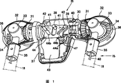
Secondly, be described in detail folding operation device 25 with reference to Fig. 1.As mentioned above, the handspike 15 of perambulator has a pair of bobbin 18,18, disposes central horizontal bar 30 between a pair of bobbin 18,18.This occasion, a pair of bobbin 18,18 are arranged on the two ends of central horizontal bar 30 and around free to rotate with the perpendicular axis of central horizontal bar 30 axis.
And, as shown in Figure 1, the 1st bevel gear 31 is installed respectively at the two ends of the central horizontal bar 30 of handspike 15.Above-mentioned the 1st bevel gear 31 is provided in the joint shell 32, and the end of above-mentioned central horizontal bar 30 is by this joint shell 32 bearings and can be around rotational.In above-mentioned joint shell 32, with the perpendicular turning cylinder 33 of the axis of above-mentioned central horizontal bar 30 by bearings, fixing the 2nd bevel gear 34 that is meshed with above-mentioned the 1st bevel gear 31 in the end of this turning cylinder 33.
Above-mentioned turning cylinder 33 is given prominence at pars intermedia and is provided with: at the bobbin installation portion of giving prominence to for the perpendicular direction of its axis 35, this bobbin installation portion 35 is outstanding outside joint shell 32 by the opening 36 that is located at joint shell 32, from this joint shell 32 to the outstanding bobbin installation portion 35 of foreign side fixing form the word shape of falling L about the top horizontal part of bobbin 18,18.The opening 36 that is located at joint shell 32 is circumferentially extending to about 90 ° scope, so that above-mentioned bobbin installation portion 35, promptly the top horizontal part of the bobbin 18,18 about can and central horizontal bar 30 for the deployed condition on the same axis or and its perpendicular folded state between move.In addition, by set pin 38 shell 37 of folding operation device 25 is fixed on central horizontal bar 30.
Like this, when the leading section of above-mentioned shell 37 is lifted upward, meanwhile make the direction of arrow of central horizontal bar 30 in Fig. 1 rotate.Respectively in the direction of arrows rotate 2nd bevel gear 34 by the 1st bevel gear 31 this moment, about the top horizontal part of bobbin 18,18 be vertical folded state from the relative central horizontal bar 30 shown in the figure, and the relative central horizontal bar 30 of the top horizontal part of the bobbin 18,18 about forming is the deployed condition on the same axis.On the contrary, when the leading section of shell 37 was pushed downwards, by the 1st bevel gear 31 and the 2nd bevel gear 34, the top horizontal part of left and right sides bobbin and above-mentioned mobile on the contrary became folded state from deployed condition.
In addition, among Fig. 1, by the 1st bevel gear 31 and the 2nd bevel gear 34 and obtain gear mechanism 34,35, by this gear mechanism 34,35 and shell 37 and constituted folding operation device 25.
In addition, being provided with the 39a of latch-release mechanism in above-mentioned shell 37, is to be used for removing the Lock Part 20 of bottom and cooperating of carriage 19 that is located at bobbin 18 (Figure 19).That is, in central horizontal bar 30, the sliding part 39 of pair of right and left is housed, this each sliding part 39 links with metal filament 40 respectively, and each metal filament 40 be respectively be located at a left side or right bobbin 18 on Lock Part 20 be connected.Be provided with the slotted hole 41 that prolongs along axis direction of pair of right and left at above-mentioned central horizontal bar 30, as shown in Figure 2, insert from sliding part 39 outstanding projections 42 and to be engaged in this slotted hole 41, make above-mentioned sliding part 39 in central horizontal bar 30, move along axis direction.
And, as shown in Figure 2, in shell 37, pivot is supporting removes the control lever that shakes 43 that aforementioned lock operation is used, and be provided with plate member 44, by shaking of this control lever 43, this plate member 44 can with the perpendicular direction of the axis of central horizontal bar 30 advance and retreat.Aforesaid operations bar 43 always applies power upward by spring 45.In addition, be provided with towards the direction of central horizontal bar 30 and bevelled dip plane 44a upward in above-mentioned plate member 44, and, be positioned at central horizontal bar 30 above above formation with respect to a pair of slotted hole 44b of the axis tilt of central horizontal bar 30, insert from aforementioned sliding part 39 outstanding projections 42 and to be engaged in this slotted hole 44b.And above-mentioned plate member 44 is because spring 46 and apply power to the direction of control lever 43.
In addition, in shell 37, in the front of above-mentioned plate member 44, that is, with the opposition side of central horizontal bar 30, set section be the L word shape safety pole 47 can with the perpendicular direction of the axis of central horizontal bar 30 advance and retreat.Above-mentioned safety pole 47 applies power by not shown spring to plate member 44 sides, and under this state, the leading section of control lever 43 contacts with the top ends of safety pole 47, stops the action of control lever 43.And, the outstanding action button 48 that is provided with below above-mentioned safety pole 47, these action button 48 processes are located at the opening 39 of shell 37 and give prominence to the foreign side of shell 37.
Like this, by action button 48 safety pole 47 is moved in Fig. 2 to left, after removing with cooperating of control lever 43, when antagonistic spring 45 and pressing operation bar 43, its leading section touches mutually with the dip plane 44a of plate member 44, because the effect of this dip plane 44a, plate member 44 moves in the vertical direction with central horizontal bar 30 axis.Therefore, because relatively the axis of central horizontal bar 30 and a pair of slotted hole 44b of bevelled and the projection 42 of giving prominence to from aforementioned sliding part 39 cooperates, about sliding part 39 move to being close to direction, by metal filament 40 Lock Part 20 is broken away from from the fastener of carriage 19, perambulator becomes folding state.
So, as mentioned above, operating operation bar 43 and make Lock Part 20 be in disarm state, the forward foot in a step 12 and the rear foot 14 for parastate fold after, when it being rotated downwards when then the leading section of shell 37 being pressed, by the 1st bevel gear 31 and the 2nd bevel gear 34, about bobbin 18 become folded state from deployed condition simultaneously with bobbin installation portion 35.And, make shell 37 when the backwards rotation from this folded state, about the top horizontal part and the central horizontal bar 30 of bobbin 18 become same axis, perambulator becomes spendable deployed condition.
That is, shell 37 is rotated can carry out the folding or expansion of perambulator, it is that available continuous action folds or launch perambulator that the user does not need hand is left from above-mentioned shell 37 fully.
In addition, in above-mentioned form of implementation, shown is the example that safety pole 47 is set, and as shown in Figure 3, also can omit safety pole 47.
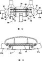
Fig. 4 and Fig. 5 are expression the 2nd forms of implementation of the present invention, and the top horizontal part of the bobbin 18 about formation handspike 15 is being fixed the cylinder-like part 50 that extends along the vertical direction respectively.And, being provided with opening 51 in the opposite flank of above-mentioned two cylinder-like parts 50, insert in the cylinder-like part 50 by this opening 51 end of the central horizontal bar 30 of handspike, the cylinder-like part 50 about being linked by above-mentioned central horizontal bar 30.That is, run through the pilot bar 52 that extends along the vertical direction at above-mentioned each cylinder-like part 50 its center.That is,, central horizontal bar 30 can be moved along above-mentioned pilot bar 52 at above-below direction in the end of these pilot bar 52 setting-in central horizontal bars 30.And, the size that is located at the opening 51 of above-mentioned cylinder-like part 50 is to make central horizontal bar 30 can move at above-below direction as mentioned above, and makes that each cylinder-like part 50 is that the center can be rotated in about 90 ° scope relative to this central horizontal bar 30 with pilot bar 52.
In addition, above-mentioned cylinder-like part 50 is to be made of the inner core 50a and the urceolus 50b that set with one heart mutually, above-mentioned inner core 50a and urceolus 50b are linked by the coil spring 53 that sets with two concentric shapes, and urceolus 50b can be by coil spring 53 relative to inner core 50a interlock and rotate.And central horizontal bar 30 inserts in the inner core 50a through urceolus 50b, and is equipped with the jut 54 that extends with the parallel axes direction of central horizontal bar 30 at its leading section.And, forming oriented groove 55 at above-mentioned inner core 50a, above-mentioned jut 54 cooperates with this oriented groove 55.
As mentioned above, obtain cylinder-like part 50, constitute folding operation device 25 by this cylinder-like part 50 by inner core 50a and urceolus 50b.
Like this, when making above-mentioned central horizontal bar 30 when above-below direction moves, because above-mentioned jut 54 cooperates with oriented groove 55, inner core 50a and urceolus 50b are that rotate at the center with pilot bar 52, the top horizontal part of the bobbin 18 about making can become with central horizontal bar 30 and is the deployed condition (Fig. 4) on the same axis, or above-mentioned top horizontal part becomes relative central horizontal bar 30 and is the folded state of vertical direction (Fig. 5).
In addition, be provided with the 56a of latch-release mechanism, be used for removing being arranged on the Lock Part 20 of bobbin 18 (Figure 19) bottom and the blocking device that cooperates and keep above-mentioned deployed condition or folded state of carriage 19 at above-mentioned central horizontal bar 30.That is, central horizontal bar 30 is that the metal part branch of コ word shape framework 30a that forms and the shell 30b that covers this framework 30a from both sides constitute by section preferably.In the central horizontal bar 30 that constitutes like this, metal filament coiling pulley 56 is installed, this coiling pulley 56 is connected with metal filament 40, and metal filament 40 is connected with the Lock Part 20 of the bobbin 18 that is located at a left side or the right side respectively.This occasion constitutes the 56a of latch-release mechanism by coiling pulley 56.
At this coiling pulley 56, control lever 57 forms as one for coaxial with fulcrum 58, this fulcrum 58 is to extend with the vertical perpendicular direction of central horizontal bar 30, by operating outstanding control lever 57 downwards from above-mentioned shell 30b, coiling pulley 56 rotates, by metal filament 40 parts 20 that unlock.
On framework 30a, shown in Fig. 6 A, Fig. 6 B, substantially at centre bearings miniature gears 60. a pair of tooth bar 61a, the 61b that is meshed therewith arranged in the both sides of this miniature gears 60, this a pair of tooth bar 61a, 61b are supported by framework 30a and can slide at left and right directions, shown in dotted line among Fig. 6 A, Fig. 6 B, be equipped with the extension frame 62 of コ word shape at the tooth bar 61a of a side towards metal filament coiling pulley 56, be used for tangling the hook portion 57a of control lever 57.
Like this, when making control lever 57 actions, its hook portion 57a joins with extension frame 62, the tooth bar 61a that makes a side moves towards the direction of the cylinder-like part 50 that leaves a side (among the figure for right-hand), at this moment, the tooth bar 61b of opposite side also slides towards the direction of the cylinder-like part 50 that leaves opposite side by miniature gears 60.
As Fig. 4 and shown in Figure 5, the lock hook sheet 63 that extends below the leading section of above-mentioned each tooth bar 61a, 61b forms upwards selectively matches with the notch recesses that is located at cylinder-like part 50.
Promptly, inner core 50a and urceolus 50b at aforementioned cylinder-like part 50, rising wood at its opening 51 forms notch recesses 64a, be when handspike is deployed condition, to match with above-mentioned lock hook sheet 63, and, lower edge at above-mentioned opening 51 forms notch recesses 64b, is to match with lock hook sheet 63 when handspike 15 is folded state.That is, notch recesses 64a and 64b are roughly 90 ° in circumferential transposition.
Like this, when perambulator was spendable deployed condition, shown in Fig. 4 and Fig. 6 A, lock hook sheet 63 cooperated with notch recesses 64a, and handspike 15 remains deployed condition.
Therefore, when operating operation bar 57, when making it be anticlockwise motion in Fig. 4, tooth bar 61a, 61b move to shrinkage direction mutually, and lock hook sheet 63 breaks away from from notch recesses 64a.At this state, when central horizontal bar 30 was pressed downwards, because the cooperating of jut 54 and oriented groove 55, inner core 50a was the center rotation with pilot bar 52.Therefore, at this state, the power that handspike 15 is applied when central horizontal bar 30 is a little upwards lifted hour, the power of putting aside at coil spring 53 because the rotation of inner core 50a reaches, urceolus 50b follows inner core 50a and in equidirectional rotation, the top horizontal part of handspike 15 moves in the vertical direction relative to central horizontal bar 30 axis, finally becomes the folded state shown in Fig. 6 B.And this moment, lock hook sheet 63 cooperated with notch recesses 64b, kept this folded state.
In addition, in the occasion of launching from folded state, as hereinbefore and operating operation bar 57, lock hook sheet 63 is broken away from from notch recesses 64b, when central horizontal bar 30 is lifted upward because the cooperating of jut 54 and oriented groove 55, inner core 50a to aforementioned opposite direction rotation.Therefore, when central horizontal bar 30 is continued upwards to lift, urceolus 50b by coil spring 53 follow inner core and with inner core 50a be that equidirectional rotates, handspike becomes deployed condition, owing to hook sheet 63 and cooperating of notch recesses 64a keep its state.
That is, only make central horizontal bar 30 knee-actions can carry out the folding or expansion of perambulator 10 in hand, the user does not need hand is left central horizontal bar 30 fully, promptly can come folding baby carrier 10 with continuous action, or carry out the expansion of perambulator 10.
Fig. 7 and Fig. 8 are the 3rd forms of implementation of the present invention, be provided with the shell 65 of folding operation device 25 at central horizontal bar 30, be equipped with metal filament coiling pulley 67 in this shell 65, this metal filament coiling pulley 67 and device in the past come rotating operation by control lever 66 equally.Like this, rotate metal filament coiling pulley 67, the releasing of carrying out the Lock Part 20 of perambulator 10 same by operating by aforesaid operations bar 66.
Both sides at above-mentioned shell 65 link by joint 68 and the bobbin 18 that constitutes handspike 15 respectively.That is, inboard folding 69 is set at the two ends of above-mentioned shell 65, the leading section of side folding within it 69 and outside folding 70 are around being connected rotationally with the perpendicular axis 71 of central horizontal bar 30 axis.And, at the bobbin installation portion 70a of above-mentioned outside folding 70 above-mentioned bobbin 18 is installed.
And, the pair of right and left driven wheel 72 that is rotated by aforesaid operations bar 66 is set in above-mentioned shell 65, its each driven wheel 72 meshes with driven gear 73 respectively.At an end of the center fixation shape memory spring 74 of this each driven gear 73, the other end of this shape memory spring 74 is fixed in the aforementioned outside folding 70.
Therefore, as shown in Figure 7, be deployed condition at handspike 15, corresponding therewith when driven wheel 72 is rotated, driven gear 73 rotates, shape memory spring 74 is applied reverse.For this reason, shape memory spring 74 is bent into memorized shape corresponding to this reverses, and promptly is bent into approximate right angle, shown in Fig. 8 left side, about outside folding 70 towards rotating with the perpendicular direction of central horizontal bar 30 axis, about bobbin 18 be retained as folded state.And in opposite occasion, shape memory spring becomes straight line, and handspike is retained as deployed condition.
Fig. 9 is expression the 4th form of implementation of the present invention, is provided with folding operation device 25a (with reference to Figure 19) at the rear side union lever 22 of the left and right sides rear foot 14 that links perambulator 10.That is, rear side union lever 22 two places therebetween that link the left and right sides rear foot are provided with joint 75,75, the two ends of intermediate bar 22a by joint 75,75 and with about end bar 22b, 22b link.
In above-mentioned intermediate bar 22a setting-in cylindrical body 76, fixedly install the 1st bevel gear 77 at the two ends of this cylindrical body 76.And, the outside folding 75a that is fixed on the joint 75 that is positioned at end 22b, 22b side at adapter shaft 78 bearings and above-mentioned the 1st bevel gear 77 ingears the 2nd bevel gear 79, the 2 bevel gears 79 of above-mentioned joint 75.
Be equipped with the control lever installing component 80 that extends towards the rear oblique upper of perambulator in above-mentioned cylindrical body 76, pivoting at this control lever installing component 80 connects the control lever 81 of the hollow form that can shake with decided angle.Be equipped with the stop pin 82 that can slide at axis direction in aforesaid operations bar 81, this stop pin 82 applies power by not shown spring and makes its front end outstanding to intermediate bar 22a direction.The other end at above-mentioned stop pin 82 is provided with outstanding to the left and right guide finger 83, this guide finger 83 is arranged on the inner face relative with aforesaid operations bar 81, and match with guide groove 84, and this guide groove 84 is towards the direction of leaving intermediate bar 22, promptly expands to open towards the rear free end side and constitute V-shape.And, being equipped with cooperation mouthful 85a, a 85b at aforementioned intermediate bar 22a, this cooperation mouthful 85a, a 85b are when rear side union lever 22 is deployed condition and folded state, insert the leading section of the above-mentioned stop pin 82 of cooperation.In addition, shown in long and short dash line, above-mentioned joint 75 tegmentum C cover.
Among Fig. 9, by the cylindrical body 76 of fixing the 1st bevel gear 77 and the 2nd bevel gear 79 and constitute folding operation device 25a.
Like this, when rear side union lever 22 was deployed condition, as shown in Figure 9, the front end of stop pin 82 cooperated with the 85a that cooperates of intermediate bar 22a, and keeps its deployed condition.Therefore, in the occasion of folding baby carrier, when waiting with pin when control lever 81 relative control lever installation portions 80 are shaken, then because cooperating of stop pin 83 and guide groove 84 makes stop pin 82 move to extracting direction, the front end of stop pin 82 is from cooperating the 85a disengaging.Therefore, when with pin etc. with aforesaid operations bar 81 when pressing down, cylindrical body 76 is rotated around intermediate bar 22a.Therefore, make the rotational of the 2nd bevel gear 79 around adapter shaft 78 by the 1st bevel gear 77, because the rotation of the 2nd bevel gear 79, end bar 22b forwards rotates, and becomes folded state.On the contrary,,, then launch end bar 22b, can make perambulator become spendable deployed condition by the 1st bevel gear 77 and the 2nd bevel gear 79 if control lever 81 is operated round about in the occasion of launching.
What Figure 10 represented is the variation of Fig. 9, and the 2nd bevel gear 79 links with outside folding 75a by be located at the coil spring 86 on the same axis with it.That is, an end of coil spring 86 and the 2nd bevel gear 79 link, and the other end and outside folding 75a link.
Like this, in this occasion, when cylindrical body 76 is rotated, the 2nd bevel gear 79 is rotated, in coil spring 86 savings turning efforts by the 1st bevel gear 77.Therefore, when rear wheel-side is lifted the back and when reducing the load of rear wheel-side a little, because savings forwards rotates outside folding 75a rotation, end bar 22b and becomes folded state in the turning effort of above-mentioned coil spring 86.
Figure 11 is expression the 5th form of implementation of the present invention, and rear side union lever 22 is provided with joint 75 at pars intermedia two places, by this joint 75 it can be folded.In the intermediate bar 22a setting-in cylindrical body 76 of 75,75 of above-mentioned joints, fix the 1st bevel gear 77 at the two ends of this cylindrical body 76.And, install and above-mentioned the 1st bevel gear 77 ingears the 2nd bevel gear 79 at the adapter shaft 78 of above-mentioned each joint 75.Fixing at above-mentioned the 2nd bevel gear 79 be the flange shape parts 87 of one with it, the front end of these flange shape parts 87 respectively by union lever 88 with about end bar 22b binding.And, as shown in figure 12, about flange shape parts 87 link by spring 89 in above-mentioned relatively adapter shaft 78 accentric positions, about end bar 22b forwards rotate the power that applies with flange shape parts 87 by these flange shape parts 87.In addition, symbol 90 is provided in a side of the control lever of cylindrical body 76.
Like this, from the folding union lever 22 of the folding rear side of deployed condition shown in Figure 11 the time, when control lever 90 by shown in the arrow and when lifting upward, by the 1st bevel gear the 77, the 2nd bevel gear 79 and flange shape parts 87, end bar 22b shown in the long and short dash line among Figure 12 and forwards rotates. this occasion, because forwards rotate and apply power by the end bar 22b of about 89 pairs on spring, so, can only apply little power to control lever 90, just can become folded state fairly simplely.
In addition, in the occasion that rear side union lever 22 is become deployed condition, by with control lever 90 to pressing down, then end bar 22b is rearward rotated by the 1st bevel gear the 77, the 2nd bevel gear 79 and flange shape parts 87, can become deployed condition.
In addition, in above-mentioned form of implementation, rear side union lever 22 is to apply power by spring 89 to folding direction, in order further to strengthen its application force, as shown in figure 13, can between the left and right end portions bar 21b of intermediate bar 21a, spring 91 be set at front side union lever 21, the end bar 21b about it is applied power to folding direction.
The 6th form of implementation of the present invention that Figure 14 and Figure 15 represent, the rear side union lever 22 of the rear foot 14 about binding can fold by 2 joints 75 of centre.At the intermediate bar 22a of above-mentioned rear side union lever 22 rotating pulley 93 is installed, this pulley 93 has the structure that is linked pair of right and left plectane 93a, 93a by the base portion of control lever 92, fixes an end of 2 one metal wires 94 towards circumferential same direction at these pulley 93 its peripheral parts.And, at above-mentioned intermediate bar 22a, from forwards being equipped with the guiding parts 95 of above-mentioned 2 one metal wires 94 that lead respectively between pair of right and left plectane 93a, the 93a, the metal filament 94 that one end is installed in above-mentioned pulley 93 is guiding across mutually by above-mentioned guiding parts 95, and the other end of this metal filament 94 with about the pars intermedia of end bar 22b link.
The control lever 92 that is located at above-mentioned pulley 93 forms hollow forms, and is equipped with in this control lever 92 along axis direction stop pin 97 slidably, and this stop pin 97 applies power by spring 96, so that its front end is outstanding to intermediate bar 22a direction.And, foreign side's free end at aforesaid operations bar 92 comes the rotating plate body 99 of bearings by knob 98, this plate body 99 is linked by connecting rod 100 with the other end of above-mentioned stop pin 97. and, be equipped with cooperation mouthful 85a, a 85b at intermediate bar 22a, this cooperation mouthful 85a, 85b are the leading sections that inserts the above-mentioned stop pin 97 of cooperation when rear side union lever 22 is deployed condition and folded state.
Like this, when rear side union lever 22 was deployed condition, as shown in figure 14, the front end of stop pin 97 cooperated with the 85a that cooperates of intermediate bar 22a, and keeps its deployed condition.Therefore, in the occasion of folding baby carrier, when knob 98 relative control lever 92 are shaken, by plate body 99 and connecting rod 100 Lock Part 97 is moved to extracting direction, the front end of stop pin 97 breaks away from from cooperating mouthful 85a.So, when aforesaid operations bar 92 when pressing down, make pulley 93 rotate around intermediate bar 22a.Therefore, the metal filament 94 that is installed in above-mentioned pulley 93 is forwards rotated end bar 22b by towing, becomes folded state.
Figure 16 is expression the 7th form of implementation of the present invention, and the cylindrical body 102 that is provided with control lever 101 is inlaid in the intermediate bar 22a of rear side union lever 22, also can rotates around this intermediate bar 22a.Form the inclined elongate 103 of a pair of Ha word shape in above-mentioned cylindrical body 102 its front face side, cooperate with the jut of establishing from a distal process of union lever 104 105 in this each inclined elongate 103, and this union lever 104 can slide near departure direction along axis direction mutually at intermediate bar 22a.And the other end of above-mentioned union lever 104 is connected at its eccentric position by bar 106 opposing tabs 75 outside folding 75a.
Like this, in deployed condition shown in Figure 16, when cylindrical body 102 is rotated, because inclined elongate 103 cooperates with jut 105, about union lever 104 to mutually moving near direction, the outside folding 75a of joint 75 is rotated around adapter shaft 78, and end bar 22b forwards side is folding.In addition, in the occasion that forms deployed condition, then carry out the operation opposite with it.
What Figure 17 represented is the 8th form of implementation of the present invention, joint 75 is set and it can be folded at pars intermedia two places of rear side union lever 22.Be provided with the control lever 107 that prolongation its end bar 22b forms as one at an end bar 22b who links by joint 75.And the pars intermedia of aforesaid operations bar 107 is linked by the pars intermedia of connecting rod 108 with another end bar 22b.
Figure 18 A is the planar view that is in the rear side union lever 22 of deployed condition, make rear side union lever 22 become the occasion of folded state from this state, when control lever 107 is rearward drawn, the end bar 22b that is located at this control lever 107 is that rotate at the center with aforesaid operations bar 107 with the adapter shaft, meanwhile, also intermediate bar 22a is forwards folding relatively for another end bar 22b by connecting rod 108, becomes the folded state shown in Figure 18 B.
Relative therewith, become the occasion of deployed condition from this folded state,, control lever 107 can become the deployed condition shown in Figure 18 A by forwards being pushed away.
Because the present invention is aforesaid formation, so can carry out the folding operation of three folded states by remote manipulation to perambulator, it is available continuous action and come folding baby carrier by fairly simple operation that the user does not need the central component parts that hand leaves perambulator fully.
Claims (4)
1. the perambulator of a folding type, it is characterized in that: have central horizontal bar, handspike and be located at the folding operation device of handspike, and above-mentioned handspike has the two ends that are located at above-mentioned central horizontal bar and around central horizontal rod axis relatively and vertical axis a pair of bobbin free to rotate; By the folding operation device, a pair of bobbin is rotated relative to the central horizontal bar,
The central horizontal bar is free to rotate around its axis; The folding operation device has: is configured between each bobbin and the central horizontal bar and links the gear mechanism of each bobbin and central horizontal bar,
Gear mechanism has the 1st bevel gear of central horizontal bar side and the 2nd bevel gear of bobbin side.
2. the perambulator of three folding types as claimed in claim 1 is characterized in that: have the Lock Part that perambulator is remained the perambulator deployed condition, be provided with the latch-release mechanism of the parts that unlock at the central horizontal bar.
3. the perambulator of three folding types as claimed in claim 2, it is characterized in that: latch-release mechanism has: sliding part, plate member, control lever, above-mentioned sliding part can be configured in the central horizontal bar with being free to slide and have projection, be connected with Lock Part by metal filament, above-mentioned plate member have the slotted hole that matches with the projection of sliding part and can with the perpendicular direction advance and retreat of the axis of central horizontal bar, the aforesaid operations bar moves plate member; The axis tilt of the relative central horizontal bar of the slotted hole of plate member, by control lever make plate member with the perpendicular direction of the axis of central horizontal bar advance and retreat, sliding part is slided in the central horizontal bar, carry out the releasing of Lock Part.
4. the perambulator of three folding types as claimed in claim 3, it is characterized in that: form bevelled hang plate below the control lever side direction in plate member, be crimped on this hang plate by the leading section with control lever, plate member is in the vertical direction advance and retreat of relative central horizontal rod axis.
Applications Claiming Priority (3)
| Application Number | Priority Date | Filing Date | Title |
|---|---|---|---|
| JP242354/2001 | 2001-08-09 | ||
| JP242354/01 | 2001-08-09 | ||
| JP2001242354A JP4937473B2 (en) | 2001-08-09 | 2001-08-09 | Stroller folding operation device |
Publications (2)
| Publication Number | Publication Date |
|---|---|
| CN1405046A CN1405046A (en) | 2003-03-26 |
| CN100366486C true CN100366486C (en) | 2008-02-06 |
Family
ID=19072637
Family Applications (1)
| Application Number | Title | Priority Date | Filing Date |
|---|---|---|---|
| CNB021286531A Expired - Fee Related CN100366486C (en) | 2001-08-09 | 2002-08-09 | Three-fold bassinet |
Country Status (8)
| Country | Link |
|---|---|
| US (2) | US6860504B2 (en) |
| EP (1) | EP1283145A3 (en) |
| JP (1) | JP4937473B2 (en) |
| KR (1) | KR101527427B1 (en) |
| CN (1) | CN100366486C (en) |
| HK (1) | HK1054532A1 (en) |
| SG (1) | SG143015A1 (en) |
| TW (1) | TW588008B (en) |
Families Citing this family (37)
| Publication number | Priority date | Publication date | Assignee | Title |
|---|---|---|---|---|
| JP4416881B2 (en) * | 1999-10-12 | 2010-02-17 | コンビ株式会社 | Stroller folding operation device |
| JP2003054418A (en) * | 2001-08-17 | 2003-02-26 | Combi Corp | Remote control device and stroller provided with the same |
| US6921102B2 (en) * | 2001-10-18 | 2005-07-26 | Ben Ming Hsia | One-hand operational control device of foldable stroller |
| JP3967271B2 (en) * | 2003-02-04 | 2007-08-29 | アップリカ育児研究会アップリカ▲葛▼西株式会社 | Folding baby carriage |
| CN1329235C (en) * | 2003-04-03 | 2007-08-01 | 好孩子儿童用品有限公司 | Secondary safety device of pull rope drive mechanism for body carriage |
| US7021650B2 (en) * | 2003-08-07 | 2006-04-04 | Wonderland Nurserygoods Co., Ltd. | Collapsing device for carrier |
| US9173802B2 (en) | 2003-10-07 | 2015-11-03 | Amg Medical, Usa. | Mobile support assembly |
| TWM256123U (en) * | 2004-02-18 | 2005-02-01 | Link Treasure Ltd | Baby umbrella stroller capable of being folded with one hand |
| ITVR20050107A1 (en) * | 2005-09-14 | 2007-03-15 | L Inglesina Baby Spa | HANDLE DEVICE, PARTICULARLY FOR STROLLERS, WHEELCHAIRS AND THE LIKE |
| NL1030330C2 (en) * | 2005-11-01 | 2007-05-03 | Royalty Bugaboo Gmbh | Foldable carriage, such as a buggy, with fixing crossbar system. |
| US7451992B2 (en) | 2006-01-31 | 2008-11-18 | Phillip Minyard Willis | Mobile support assembly |
| US7717457B2 (en) * | 2006-05-15 | 2010-05-18 | Wonderland Nurserygoods Co., Ltd. | Stroller with spring-assisted fold mechanism |
| TWM325960U (en) * | 2006-09-29 | 2008-01-21 | Golden Point Marketing Ltd | Folding control mechanism for baby stroller |
| US7731220B2 (en) * | 2006-12-19 | 2010-06-08 | Wonderland Nurserygoods Co., Ltd. | Frame assembly for double-seat baby stroller |
| CN201082718Y (en) * | 2007-07-19 | 2008-07-09 | 明门实业股份有限公司 | Single-hand folding actuating mechanism for baby carriage |
| US20090102149A1 (en) * | 2007-10-22 | 2009-04-23 | Graco Children's Products Inc. | Foldable pushcart and foldable baby carriage |
| US8439376B2 (en) * | 2008-07-08 | 2013-05-14 | Amg Medical, Usa. | Mobile support assembly |
| JP5234802B2 (en) * | 2009-04-22 | 2013-07-10 | 株式会社リッチェル | Folding stroller unlocking device, folding stroller equipped with the unlocking device |
| CN102211604B (en) * | 2010-04-09 | 2014-03-05 | 明门香港股份有限公司 | Foldable baby bearing device |
| NL2005363C2 (en) * | 2010-09-16 | 2012-03-19 | Mutsy Bv | DEVICES FOR SUPPORTING A CHILD. |
| JP5963394B2 (en) * | 2011-03-03 | 2016-08-03 | アップリカ・チルドレンズプロダクツ合同会社 | Folding baby carriage |
| US8517412B2 (en) | 2011-09-22 | 2013-08-27 | Baby Trend Inc. | Foldable stroller frame having three sections joined to and foldable around a common hub structure |
| US20130113185A1 (en) * | 2011-11-07 | 2013-05-09 | Dynamic Brands, Llc | Baby stroller |
| US9199658B2 (en) * | 2012-06-22 | 2015-12-01 | Khai Gan Chuah | Baby stroller folding mechanism |
| CN103661544B (en) * | 2012-08-30 | 2016-03-02 | 明门香港股份有限公司 | Joint arrangement |
| JP5548747B2 (en) * | 2012-09-25 | 2014-07-16 | 株式会社島製作所 | Locking device for slide member and handcart equipped with this locking device |
| US9463822B2 (en) | 2014-01-10 | 2016-10-11 | Dorel Juvenile Group, Inc. | Stroller |
| CN203766857U (en) | 2014-03-27 | 2014-08-13 | 克斯克管理公司 | Cart |
| US9315205B2 (en) * | 2014-09-18 | 2016-04-19 | Khai Gan Chuah | Folding mechanism of baby stroller |
| CN104986207B (en) * | 2015-07-09 | 2018-01-30 | 廖整辉 | Folding baby carrier |
| US9308929B1 (en) | 2015-08-17 | 2016-04-12 | Dorel Juvenile Group, Inc. | Stroller |
| GB2547515B (en) * | 2015-12-19 | 2019-09-04 | Wonderland Switzerland Ag | Infant stroller apparatus |
| CN106004965B (en) * | 2016-06-08 | 2019-05-10 | 中山盛加儿童用品有限公司 | A kind of folding pushchair |
| EP3747731B1 (en) * | 2018-07-16 | 2023-01-18 | Shanghai Dorel Juvenile Co., Ltd. | Handle folding mechanism, three-fold handle employing the folding mechanism, and trolley having the same |
| CN114475756A (en) * | 2020-11-13 | 2022-05-13 | 明门瑞士股份有限公司 | Handrail folding mechanism and baby carriage |
| CN112462098B (en) * | 2020-11-30 | 2022-07-29 | 广东电网有限责任公司韶关供电局 | Folding operating rod |
| KR102411848B1 (en) * | 2020-12-08 | 2022-06-22 | 주식회사 이노디자인 | Folding type handle |
Citations (5)
| Publication number | Priority date | Publication date | Assignee | Title |
|---|---|---|---|---|
| US4614454A (en) * | 1984-01-11 | 1986-09-30 | Aprica Kassai Kabushikikaisha | Baby carriage grip rod locking mechanism |
| CN1137253A (en) * | 1994-10-20 | 1996-12-04 | 阿普丽佳葛西株式会社 | Crip rod of baby carriage |
| US6068284A (en) * | 1997-07-29 | 2000-05-30 | Graco Children's Products Inc. | Stroller with one hand release mechanism and one hand release mechanism thereof |
| US6129373A (en) * | 2000-02-04 | 2000-10-10 | Cheng; Kenny | Single-handed folding device |
| CN1291569A (en) * | 1999-10-12 | 2001-04-18 | 宫比株式会社 | Folding device of stroller |
Family Cites Families (27)
| Publication number | Priority date | Publication date | Assignee | Title |
|---|---|---|---|---|
| US2437778A (en) * | 1944-02-02 | 1948-03-16 | Walkabout Company | Portable support for invalids |
| US4191397A (en) * | 1977-06-15 | 1980-03-04 | Kassai Kabushikikaisha | Baby carriage |
| JPS5858972U (en) * | 1981-10-16 | 1983-04-21 | アップリカ葛西株式会社 | back legs of baby carriage |
| JPS58202157A (en) * | 1982-05-19 | 1983-11-25 | アップリカ葛西株式会社 | Structure of connecting section of push bar and push-bar connecting rod of baby carriage |
| JPS59106366A (en) * | 1982-12-11 | 1984-06-20 | 象印ベビ−株式会社 | Baby car |
| JPS59149563U (en) * | 1983-03-28 | 1984-10-05 | アップリカ葛西株式会社 | Connection structure between push rod and push rod connecting rod of baby carriage |
| JPS59157964U (en) * | 1983-04-08 | 1984-10-23 | アップリカ葛西株式会社 | Connection structure between push rod and push rod connecting rod of baby carriage |
| JPS60199763A (en) * | 1984-03-23 | 1985-10-09 | アップリカ葛西株式会社 | Locking mechanism of gripping bar for baby carriage |
| US4765645A (en) * | 1987-01-30 | 1988-08-23 | Louis Shamie | Safety spreader bar lock for umbrella stroller |
| JPH0638777Y2 (en) * | 1988-05-17 | 1994-10-12 | アップリカ葛西株式会社 | Lock mechanism for the grip of the baby carriage |
| US5205579A (en) * | 1990-10-08 | 1993-04-27 | Combi Corporation | Handle bar for baby carriage |
| JP3040496B2 (en) * | 1991-01-11 | 2000-05-15 | アップリカ▲葛▼西株式会社 | Folding stroller and folding mechanism used therein |
| KR960003727Y1 (en) * | 1994-02-05 | 1996-05-06 | 주식회사 한국아프리카 | Baby carrier |
| US5535483A (en) * | 1994-02-11 | 1996-07-16 | Jane, S.A. | Locking and unlocking device for the folding of baby carriages |
| JP3311163B2 (en) * | 1994-09-21 | 2002-08-05 | アップリカ▲葛▼西株式会社 | Stroller and method of manufacturing seat plate for its seat |
| JP3764515B2 (en) * | 1994-11-25 | 2006-04-12 | コンビ株式会社 | Folding seating device |
| TW280801B (en) * | 1994-12-26 | 1996-07-11 | Aprica Kassai Kk | |
| DE29509125U1 (en) * | 1995-06-02 | 1995-08-17 | Rudi Schaller Metalltechnik Gm | Frame for a collapsible children's or doll's seat or couchette |
| US5664798A (en) * | 1995-07-11 | 1997-09-09 | Lu Kuang Incorporation | Automatic folding frame for baby carriage |
| GB2318099B (en) * | 1996-10-10 | 2000-11-29 | Huang Li Chu Chen | Foldable mechanism for use in a stroller |
| JP2000108904A (en) * | 1998-10-06 | 2000-04-18 | Combi Corp | Opening and closing operation mechanism of stroller folding mechanism |
| NL1012334C2 (en) * | 1999-06-15 | 2000-12-18 | Maxi Miliaan Bv | Stroller. |
| KR200164019Y1 (en) * | 1999-07-07 | 2000-02-15 | 주식회사햇님토이 | Baby carriage |
| US6339862B1 (en) * | 2000-02-09 | 2002-01-22 | Kenny Cheng | Single-handed folding device (II) |
| CN2440403Y (en) * | 2000-07-26 | 2001-08-01 | 中山市隆成日用制品有限公司 | Collapsing structure for pushchair by one hand |
| JP4689018B2 (en) * | 2000-09-21 | 2011-05-25 | コンビ株式会社 | Twin stroller |
| JP2003054418A (en) * | 2001-08-17 | 2003-02-26 | Combi Corp | Remote control device and stroller provided with the same |
-
2001
- 2001-08-09 JP JP2001242354A patent/JP4937473B2/en not_active Expired - Fee Related
-
2002
- 2002-08-08 SG SG200204791-8A patent/SG143015A1/en unknown
- 2002-08-08 KR KR1020020046784A patent/KR101527427B1/en not_active IP Right Cessation
- 2002-08-08 TW TW091117919A patent/TW588008B/en not_active IP Right Cessation
- 2002-08-08 US US10/214,488 patent/US6860504B2/en not_active Expired - Fee Related
- 2002-08-09 CN CNB021286531A patent/CN100366486C/en not_active Expired - Fee Related
- 2002-08-09 EP EP02017952A patent/EP1283145A3/en not_active Withdrawn
-
2003
- 2003-09-23 HK HK03106836A patent/HK1054532A1/en unknown
-
2005
- 2005-01-18 US US11/035,957 patent/US7168728B2/en not_active Expired - Fee Related
Patent Citations (5)
| Publication number | Priority date | Publication date | Assignee | Title |
|---|---|---|---|---|
| US4614454A (en) * | 1984-01-11 | 1986-09-30 | Aprica Kassai Kabushikikaisha | Baby carriage grip rod locking mechanism |
| CN1137253A (en) * | 1994-10-20 | 1996-12-04 | 阿普丽佳葛西株式会社 | Crip rod of baby carriage |
| US6068284A (en) * | 1997-07-29 | 2000-05-30 | Graco Children's Products Inc. | Stroller with one hand release mechanism and one hand release mechanism thereof |
| CN1291569A (en) * | 1999-10-12 | 2001-04-18 | 宫比株式会社 | Folding device of stroller |
| US6129373A (en) * | 2000-02-04 | 2000-10-10 | Cheng; Kenny | Single-handed folding device |
Also Published As
| Publication number | Publication date |
|---|---|
| US20030030250A1 (en) | 2003-02-13 |
| US6860504B2 (en) | 2005-03-01 |
| HK1054532A1 (en) | 2003-12-05 |
| KR20030014649A (en) | 2003-02-19 |
| CN1405046A (en) | 2003-03-26 |
| EP1283145A2 (en) | 2003-02-12 |
| JP2003054413A (en) | 2003-02-26 |
| JP4937473B2 (en) | 2012-05-23 |
| US20050121882A1 (en) | 2005-06-09 |
| KR101527427B1 (en) | 2015-06-08 |
| TW588008B (en) | 2004-05-21 |
| SG143015A1 (en) | 2008-06-27 |
| US7168728B2 (en) | 2007-01-30 |
| EP1283145A3 (en) | 2005-10-12 |
Similar Documents
| Publication | Publication Date | Title |
|---|---|---|
| CN100366486C (en) | Three-fold bassinet | |
| CN101448695B (en) | Handle for collapsible stroller | |
| JPH03114970A (en) | Foldable baby car | |
| CN109291982B (en) | Child cart | |
| CN106314516B (en) | Baby-carrier framework | |
| CN101337555B (en) | Foldable baby carriage and folding method thereof | |
| CN215904558U (en) | Folding cart | |
| CN214325200U (en) | Children's handcart | |
| CN107031692B (en) | A kind of go-cart for double child | |
| CN207737353U (en) | A kind of cart skeleton and children trolley | |
| CN205872147U (en) | A main joint for perambulator | |
| CN106428181A (en) | Baby carriage | |
| CN212828876U (en) | Scooter folding mechanism and scooter | |
| CN111776121A (en) | Foldable portable electric vehicle | |
| CN110979438A (en) | Folding child's bike | |
| CN111071331A (en) | Automatic folding and standing-keeping baby stroller | |
| CN216232519U (en) | Seat folding assembly and child stroller | |
| CN210680889U (en) | Children's barrow | |
| CN211642457U (en) | Folding tricycle | |
| CN210526629U (en) | Novel frame folding mechanism | |
| CN211617830U (en) | Foldable baby carriage | |
| EP4132840B1 (en) | Convertible device to be used as sports equipment for children or as a pram | |
| CN211617829U (en) | Folding child's bike | |
| CN108032899A (en) | A kind of perambulator | |
| EP3733477B1 (en) | Foldable frame for a shopping trolley |
Legal Events
| Date | Code | Title | Description |
|---|---|---|---|
| C06 | Publication | ||
| PB01 | Publication | ||
| C10 | Entry into substantive examination | ||
| SE01 | Entry into force of request for substantive examination | ||
| C14 | Grant of patent or utility model | ||
| GR01 | Patent grant | ||
| REG | Reference to a national code |
Ref country code: HK Ref legal event code: GR Ref document number: 1054532 Country of ref document: HK |
|
| CF01 | Termination of patent right due to non-payment of annual fee |
Granted publication date: 20080206 Termination date: 20160809 |
|
| CF01 | Termination of patent right due to non-payment of annual fee |