CN100363992C - Objective-lens driving apparatus, optical pickup and optical disk apparatus - Google Patents
Objective-lens driving apparatus, optical pickup and optical disk apparatus Download PDFInfo
- Publication number
- CN100363992C CN100363992C CNB2006100010460A CN200610001046A CN100363992C CN 100363992 C CN100363992 C CN 100363992C CN B2006100010460 A CNB2006100010460 A CN B2006100010460A CN 200610001046 A CN200610001046 A CN 200610001046A CN 100363992 C CN100363992 C CN 100363992C
- Authority
- CN
- China
- Prior art keywords
- mentioned
- magnet
- cut zone
- tracking
- coil
- Prior art date
- Legal status (The legal status is an assumption and is not a legal conclusion. Google has not performed a legal analysis and makes no representation as to the accuracy of the status listed.)
- Expired - Fee Related
Links
Images


Classifications
-
- G—PHYSICS
- G11—INFORMATION STORAGE
- G11B—INFORMATION STORAGE BASED ON RELATIVE MOVEMENT BETWEEN RECORD CARRIER AND TRANSDUCER
- G11B7/00—Recording or reproducing by optical means, e.g. recording using a thermal beam of optical radiation by modifying optical properties or the physical structure, reproducing using an optical beam at lower power by sensing optical properties; Record carriers therefor
- G11B7/08—Disposition or mounting of heads or light sources relatively to record carriers
- G11B7/09—Disposition or mounting of heads or light sources relatively to record carriers with provision for moving the light beam or focus plane for the purpose of maintaining alignment of the light beam relative to the record carrier during transducing operation, e.g. to compensate for surface irregularities of the latter or for track following
- G11B7/095—Disposition or mounting of heads or light sources relatively to record carriers with provision for moving the light beam or focus plane for the purpose of maintaining alignment of the light beam relative to the record carrier during transducing operation, e.g. to compensate for surface irregularities of the latter or for track following specially adapted for discs, e.g. for compensation of eccentricity or wobble
-
- G—PHYSICS
- G11—INFORMATION STORAGE
- G11B—INFORMATION STORAGE BASED ON RELATIVE MOVEMENT BETWEEN RECORD CARRIER AND TRANSDUCER
- G11B7/00—Recording or reproducing by optical means, e.g. recording using a thermal beam of optical radiation by modifying optical properties or the physical structure, reproducing using an optical beam at lower power by sensing optical properties; Record carriers therefor
- G11B7/08—Disposition or mounting of heads or light sources relatively to record carriers
- G11B7/09—Disposition or mounting of heads or light sources relatively to record carriers with provision for moving the light beam or focus plane for the purpose of maintaining alignment of the light beam relative to the record carrier during transducing operation, e.g. to compensate for surface irregularities of the latter or for track following
- G11B7/0925—Electromechanical actuators for lens positioning
- G11B7/0932—Details of sprung supports
-
- G—PHYSICS
- G11—INFORMATION STORAGE
- G11B—INFORMATION STORAGE BASED ON RELATIVE MOVEMENT BETWEEN RECORD CARRIER AND TRANSDUCER
- G11B7/00—Recording or reproducing by optical means, e.g. recording using a thermal beam of optical radiation by modifying optical properties or the physical structure, reproducing using an optical beam at lower power by sensing optical properties; Record carriers therefor
- G11B7/08—Disposition or mounting of heads or light sources relatively to record carriers
- G11B7/085—Disposition or mounting of heads or light sources relatively to record carriers with provision for moving the light beam into, or out of, its operative position or across tracks, otherwise than during the transducing operation, e.g. for adjustment or preliminary positioning or track change or selection
-
- G—PHYSICS
- G11—INFORMATION STORAGE
- G11B—INFORMATION STORAGE BASED ON RELATIVE MOVEMENT BETWEEN RECORD CARRIER AND TRANSDUCER
- G11B7/00—Recording or reproducing by optical means, e.g. recording using a thermal beam of optical radiation by modifying optical properties or the physical structure, reproducing using an optical beam at lower power by sensing optical properties; Record carriers therefor
- G11B7/08—Disposition or mounting of heads or light sources relatively to record carriers
- G11B7/09—Disposition or mounting of heads or light sources relatively to record carriers with provision for moving the light beam or focus plane for the purpose of maintaining alignment of the light beam relative to the record carrier during transducing operation, e.g. to compensate for surface irregularities of the latter or for track following
- G11B7/0925—Electromechanical actuators for lens positioning
- G11B7/0933—Details of stationary parts
-
- G—PHYSICS
- G11—INFORMATION STORAGE
- G11B—INFORMATION STORAGE BASED ON RELATIVE MOVEMENT BETWEEN RECORD CARRIER AND TRANSDUCER
- G11B7/00—Recording or reproducing by optical means, e.g. recording using a thermal beam of optical radiation by modifying optical properties or the physical structure, reproducing using an optical beam at lower power by sensing optical properties; Record carriers therefor
- G11B7/08—Disposition or mounting of heads or light sources relatively to record carriers
- G11B7/09—Disposition or mounting of heads or light sources relatively to record carriers with provision for moving the light beam or focus plane for the purpose of maintaining alignment of the light beam relative to the record carrier during transducing operation, e.g. to compensate for surface irregularities of the latter or for track following
- G11B7/0925—Electromechanical actuators for lens positioning
- G11B7/0935—Details of the moving parts
-
- G—PHYSICS
- G11—INFORMATION STORAGE
- G11B—INFORMATION STORAGE BASED ON RELATIVE MOVEMENT BETWEEN RECORD CARRIER AND TRANSDUCER
- G11B7/00—Recording or reproducing by optical means, e.g. recording using a thermal beam of optical radiation by modifying optical properties or the physical structure, reproducing using an optical beam at lower power by sensing optical properties; Record carriers therefor
- G11B7/08—Disposition or mounting of heads or light sources relatively to record carriers
- G11B7/09—Disposition or mounting of heads or light sources relatively to record carriers with provision for moving the light beam or focus plane for the purpose of maintaining alignment of the light beam relative to the record carrier during transducing operation, e.g. to compensate for surface irregularities of the latter or for track following
- G11B7/095—Disposition or mounting of heads or light sources relatively to record carriers with provision for moving the light beam or focus plane for the purpose of maintaining alignment of the light beam relative to the record carrier during transducing operation, e.g. to compensate for surface irregularities of the latter or for track following specially adapted for discs, e.g. for compensation of eccentricity or wobble
- G11B7/0956—Disposition or mounting of heads or light sources relatively to record carriers with provision for moving the light beam or focus plane for the purpose of maintaining alignment of the light beam relative to the record carrier during transducing operation, e.g. to compensate for surface irregularities of the latter or for track following specially adapted for discs, e.g. for compensation of eccentricity or wobble to compensate for tilt, skew, warp or inclination of the disc, i.e. maintain the optical axis at right angles to the disc
Landscapes
- Optical Recording Or Reproduction (AREA)
Abstract
The present invention provides an objective-lens driving apparatus in which the phase delay is small in focusing-response characteristic and which excels in resonance characteristic in high-frequency bands. The objective-lens driving apparatus includes a movable unit that has a lens holder holding an objective lens, a fixed unit that is spaced apart from the movable unit in a tangential direction, elastic support members that support the movable unit, enabling the movable unit to move with respect to the fixed unit in the focusing direction and tracking direction and to incline in a tilt direction, a first magnet, and a second magnet that is magnetized in a direction opposite to a magnetization direction of the first magnet. The lens holder has tracking coils, focusing coils, a first tilt coil that is wound around an axis extending in the focusing direction and generates drive forces acting in the tilt direction, and a second tilt coil that is wound around in a direction opposite to the winding direction of the first tilt coil, and generates drive forces acting in the tilt direction.
Description
Technical field
The present invention relates to a kind of objective lens device, adopt the optical pickup apparatus and the optical disc apparatus of this objective lens device.Above-mentioned objective lens device is used for optical pickup apparatus that information recording carriers such as CD are write down and/or reproduce, and the movable part of above-mentioned objective lens device can be with respect to fixed part to these 3 directions actions of focus direction, tracking direction and vergence direction.
Background technology
Information recording carriers such as CD are carried out be provided with optical pickup apparatus in the optical disc apparatus of record-playback of information signal, this optical pickup apparatus moves along the radial direction of CD, to this CD irradiating laser.
In optical pickup apparatus, be provided with objective lens device, carry out focus adjustment, tracking adjusting by this objective lens device, carry out luminous point and regulate shine laser on the CD by object lens, make by object lens and shine laser spot optically focused on the CD to the track record of CD.This focus adjustment is the object lens that make on the movable part that remains on above-mentioned objective lens device, along leave or near the direction of the signal recording surface of CD, be the focus direction action, carry out focus adjustment.This tracking regulate be make object lens along the roughly radial direction of CD, be the action of tracking direction, carry out that tracking regulates.
Like this, in this optical pickup apparatus, normally carry out focus adjustment and tracking adjusting, in recent years with objective lens device, in order to improve laser spot, the objective lens device (with reference to TOHKEMY 2001-93177 communique) of so-called 3 shaft-type governors etc. has been proposed to tracing ability of track record etc.This 3 shaft-type governor is regulated 2 such adjustings except carrying out focus adjustment and tracking, can also make the signal record face tilt of movable part with respect to CD, regulates when also can the CD in rotation producing surface vibration etc.
In the objective lens device of this 3 shaft-type governor etc., movable part can be with respect to fixed part in focus direction, tracking direction and vergence direction action.Vergence direction described here is meant around the direction of rotating with the radial direction quadrature of CD and the axle parallel with the tangential direction that becomes the CD tangential direction.
For example, known have an objective lens device shown in Figure 15, this objective lens device is to constitute like this, keeps the movable part of object lens to be bearing on the fixed block by support spring with can move freely, is used to make moveable block to be located at movable part with respect to the tilt coil that fixed block tilts.
As shown in figure 15, objective lens device 101 has the yoke 102 that is inserted in focusing coil described later and the tilt coil, keeps the movable part 104 of object lens 103, leave the fixed part 105 that disposing mutually with movable part 104, be located on the fixed part 105 and with the pair of magnets 106,107 and the elastic bearing component 108 of movable part 104 relative configurations, this elastic bearing component 108 support movable parts 104 also can make movable part 104 with respect to fixed part 105 to focus direction F
CSAnd tracking direction T
RKMove, and can make movable part 104 adipping T
ILTilt.
As Figure 15 and shown in Figure 16, on movable part 105, be provided with at focus direction F
CSThe focusing coil 111 of wireline reel is arranged, at tangential direction T
ANThe tracking coil 112,113,114,115 of wireline reel is arranged, at focus direction F
CSThe tilt coil 116,117 that wireline reel is arranged.
As Figure 15 and shown in Figure 16, in the objective lens device 101, when when focusing coil 111, tracking coil 112~115 and tilt coil 116,117 are supplied with drive current, the relation of the flow direction that produces according to the flow direction of drive current with by pair of magnets 106,107 and yoke 102, movable part 104 with respect to fixed part 105 at focus direction F
CS, tracking direction T
RK, and vergence direction T
ILMove.
Thus, objective lens device 101 except carrying out focus adjustment and tracking regulate, is regulated in the time of can also producing surface vibration etc. on CD, can improve the tracing ability of laser spot to track record.
Because this objective lens device 101 is such magnetic loop structures, has at focus direction F
CSHave the voice coil-type focusing coil 111 of wireline reel and insert yoke 102 in this focusing coil 111.So in focusing on response characteristic, the phase delay that the inductance composition causes is big, in high power speed recording transcriber, may have problems in servo design.
In addition, as shown in figure 17, in this objective lens device 101, because the driving force F that focuses on
S3Act on tracking direction T
RKCentral portion, then this focusing thrust concentrates on central authorities, thereby causes resonance mode easily, be that the first order buckling pattern of movable part is energized, and the resonance peak height is increased.
Summary of the invention
The object of the present invention is to provide a kind of objective lens device, optical pickup apparatus and optical disc apparatus, objective lens device of the present invention, in focusing on response characteristic, can reduce phase delay, focus on the first order buckling pattern that driving force can not encourage movable part, can obtain good high-frequency resonance characteristic.
To achieve these goals, objective lens device of the present invention comprises:
Movable part, it has the lens mount that keeps object lens;
Fixed part, its with the focus direction of object lens and the tangential direction of tracking direction quadrature, be separated with compartment of terrain configuration with above-mentioned movable part;
Elastic bearing component, connect movable part and fixed part respectively, the supporting movable part also can move movable part with respect to fixed part, and movable part is tilted towards the vergence direction with respect to the face tilt that is parallel to above-mentioned tangential direction on focus direction and tracking direction;
The 1st magnet, it relatively disposes with lens mount on tangential direction, have the 1st to the 4th cut zone, the 1st to the 4th cut zone be by with the 1st magnet in focus direction and the tracking direction is cut apart and make the each several part that is split to form be magnetized into its direction of magnetization respectively forms towards tangential direction;
The 2nd magnet, it relatively disposes with the 1st magnet on tangential direction, have the 5th to the 8th cut zone, the 5th to the 8th cut zone be by with the 2nd magnet in above-mentioned focus direction and above-mentioned tracking direction is cut apart and the each several part that is split to form is magnetized into respectively with above-mentioned the 1st magnet oppositely forms;
And lens mount is provided with tracking coil, focusing coil, the 1st tilt coil and the 2nd tilt coil;
Above-mentioned tracking coil, be located at respectively corresponding with 7th and 8th cut zone relative of 5th and 6th cut zone relative, the 2nd magnet of adjacent the 3rd and the 4th cut zone, the 2nd magnet on the tracking direction at the 1st and the 2nd adjacent on tracking direction cut zone, the 1st magnet of the 1st magnet with the 1st and the 2nd cut zone with the 3rd and the 4th cut zone, make this tracking coil produce 4 positions of driving force in the tracking direction;
Above-mentioned focusing coil, be located at respectively corresponding with 6th and 8th cut zone relative of 5th and 7th cut zone relative, the 2nd magnet of adjacent the 2nd and the 4th cut zone, the 2nd magnet on focus direction at the 1st and the 3rd adjacent on focus direction cut zone, the 1st magnet of the 1st magnet with the 1st and the 3rd cut zone with the 2nd and the 4th cut zone, make this focusing coil produce 4 positions of driving force in focus direction;
Above-mentioned the 1st tilt coil, focus direction reeled as the wireline reel direction to form, corresponding with the 5th and the 6th cut zone of adjacent the 1st and the 2nd cut zone on the tracking direction of the 1st magnet and the 2nd magnet, make the 1st tilt coil produce driving force at vergence direction;
Above-mentioned the 2nd tilt coil, its coiling direction is opposite with the coiling direction of the 1st tilt coil, corresponding with the 7th and the 8th cut zone of adjacent the 3rd and the 4th cut zone on the tracking direction of the 1st magnet and the 2nd magnet, make the 2nd tilt coil produce driving force at vergence direction.
In addition, to achieve these goals, optical pickup apparatus of the present invention has the mobile foundation that moves along the radial direction that is installed in the CD on the Pan Tai and is configured in objective lens device on this mobile foundation, and this objective lens device is to adopt above-mentioned objective lens device.
In addition, to achieve these goals, optical disc apparatus of the present invention have the Pan Tai of fixing disc and by object lens to being installed in the optical pickup apparatus of the CD irradiating laser on this Pan Tai, optical pickup apparatus has the mobile foundation that moves along the radial direction that is installed in the CD on the Pan Tai and is configured in objective lens device on this mobile foundation, and this objective lens device is to adopt above-mentioned objective lens device.
Objective lens device of the present invention, optical pickup apparatus and optical disc apparatus focusing on the response characteristic, can reduce phase delay, in high power speed recording transcriber, can carry out servo design easily.In addition, objective lens device of the present invention, optical pickup apparatus and optical disc apparatus can prevent from can obtain good resonance characteristics by focusing on the excitation that driving force causes the first order buckling pattern of movable part in high frequency.
Description of drawings
Fig. 1 has been to use the approximate three-dimensional map of record reproducing device of the present invention.
Fig. 2 is the stereographic map of objective lens device of the present invention.
Fig. 3 be expression objective lens device of the present invention yoke pedestal, fixed part and moving part from the stereographic map of state.
Fig. 4 is the stereographic map of expression objective lens device rear side of the present invention.
Fig. 5 is the rear side approximate three-dimensional map of the position relation of expression magnet of objective lens device of the present invention and coil.
Fig. 6 is the summary exploded perspective view of the configuration of expression magnet of objective lens device of the present invention and printed coil.
Fig. 7 is the figure of direction of magnetization of the magnet of expression objective lens device of the present invention; (a) be the planimetric map in the face of lens mount one side of the 1st magnet; (b) be the planimetric map in the face of lens mount one side of the 2nd magnet.
Fig. 8 is the summary exploded perspective view of the configuration of expression magnet of objective lens device of the present invention and coil.
Fig. 9 be the expression movable part that is used for illustrating objective lens device of the present invention the first order buckling resonance mode resonance and focus on the summary side elevation of the relation of thrust.
Figure 10 is the figure that is used to illustrate the order of the tilt coil that forms objective lens device of the present invention; (a) be left side view, expression is perpendicular to the one side of tracking direction, and is illustrated in the state of the coil that begins on the jut that begins usefulness of reeling to reel; (b) be the planimetric map of the coiling direction of expression the 1st tilt coil; (c) be right side view, represent another side, and represent the state that the 1st tilt coil is reeled and finished perpendicular to the tracking direction; (d) be left side view, expression makes coiling direction counter-rotating, the state of the 2nd tilt coil that begins to reel; (e) be the planimetric map of the coiling direction of expression the 2nd tilt coil; (f) be the right side view of expression the 2nd tilt coil coiling completion status.
Figure 11 is figure in the objective lens device of expression objective lens device of the present invention and comparative example, that phase place and gain change with frequency change; (a) be the figure that the expression gain changes with frequency change; (b) be the figure that the expression phase place changes with frequency change.
Figure 12 is figure in the objective lens device of expression objective lens device of the present invention and comparative example, that gain changes with frequency change.
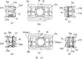
Figure 13 is another example that expression constitutes the 1st and the 2nd magnet of objective lens device of the present invention; (a) be exploded perspective view; (b) be that expression is with the stereographic map of each magnet at the state of tracking direction joint.
Figure 14 is the another example that expression constitutes the 1st and the 2nd magnet of objective lens device of the present invention; (a) be exploded perspective view; (b) be that expression is with the stereographic map of each magnet at the state of focus direction joint.
Figure 15 is the stereographic map of objective lens device before.
Figure 16 is an approximate three-dimensional map of representing the position relation of focusing coil, tracking coil and tilt coil in the objective lens device before.
Figure 17 be the expression movable part that is used for illustrating objective lens device before the first order buckling resonance mode resonance and focus on the summary side elevation of the relation of thrust.
Embodiment
Below, use record reproducing device of the present invention with reference to description of drawings.
This record reproducing device 1 is to carry out the record of information signal and/or the record reproducing device of reproduction to CD 2.The CD 2 that writes down and/or reproduce with this record reproducing device 1, for example can use CD (Compact Disc), DVD (Digital VersatileDisc), the CD-R (Recordable) that can append information and DVD-R (Recordable), the CD-RW (Rewritable) that can rewrite information, DVD-RW (Rewritable), DVD+RW CDs such as (Rewritable), in addition, adopt the CD that emission wavelength is lacked, that wavelength is about the high density recording carried out of the semiconductor laser of (bluish violet) about 405nm, photomagneto disk etc. in addition.
Specifically, as shown in Figure 1, this record reproducing device 1 disposes each required member and each mechanism in housing 3, is formed with not shown dish and inserts mouth on housing 3.
In housing 3, dispose not shown base, on the motor reel that is installed on the spindle drive motor on this base, be fixed with dish platform 4.
As shown in Figure 1, optical pickup apparatus 7 has mobile foundation 8, be located at the needed optics on this mobile foundation 8 and be configured in objective lens device 9 on the mobile foundation 8, and the 8a of bearing portion, the 8b that are located at mobile foundation 8 both ends can be supported on guidance axis 5 respectively with being free to slide.
The not shown nut member that is located on the mobile foundation 8 engages with threads of lead screw 6, when leading screw 6 is rotated by the feed motor driving, nut member is towards being transferred with the corresponding direction of the sense of rotation of leading screw 6, and optical pickup apparatus 7 moves along the radial direction that is installed in the CD 2 on the dish platform 4.
As Fig. 2, Fig. 3, shown in Figure 4, objective lens device 9 has yoke pedestal 10, not shown fixed head, movable part 12, fixed part 11 and a plurality of elastic bearing component 16.Not shown fixed head is fixed on the mobile foundation 8, at tangential direction T
ANGo up with yoke pedestal 10 and be provided with mutually with leaving; Movable part 12 has the lens mount 15 that keeps object lens 14; Fixed part 11 with the focus direction F of object lens 14
CSAnd tracking direction T
RKThe tangential direction T of quadrature
ANLast and movable part 12 is separated with the compartment of terrain and is provided with; A plurality of elastic bearing components 16 connect movable part 12 and fixed part 11 respectively, are supporting movable part 12 and are making the movable part 12 can be with respect to fixed part 11 at focus direction F
CSAnd tracking direction T
RKMove, and supporting movable part 12 can make movable part 12 towards vergence direction T
ILTilt this vergence direction T
ILWith respect to the tangential direction T that becomes the CD tangential direction
ANParallel face tilt.
At the opposite face of yoke 10b, 10c, promptly in the face of on the surface of lens mount 15, be separately installed with the 1st magnet 21 and the 2nd magnet 22.
As Fig. 3, Fig. 6, shown in Figure 7, the 1st magnet 21 is at tangential direction T
ANAbove lens mount 15 ground are disposed, have the 1st cut zone the 31, the 2nd cut zone the 32, the 3rd cut zone the 33, the 4th cut zone 34, the 1 cut zone the 31, the 2nd cut zone the 32, the 3rd cut zone the 33, the 4th cut zone 34 and be by with the 1st magnet 21 respectively at focus direction F
CSWith tracking direction T
RKCut apart, and make the each several part that is split to form be magnetized into separately direction of magnetization respectively towards tangential direction T
ANObtain.
In the 1st magnet 21, the 1st cut zone the 31, the 2nd cut zone the 32, the 3rd cut zone the 33, the 4th cut zone 34 15 that face mutually with lens mount, i.e. face one side relative with aftermentioned the 1st printed coil the 39, the 1st tilt coil 51 and the 2nd tilt coil 52 be for example with the 1st magnet 21 respectively at tracking direction T
RKAnd focus direction F
CSOn be divided into two parts, be divided into that 4 parts form altogether, form essentially rectangular, the 1st cut zone 31 and the 4th cut zone 34 that are positioned at position, a diagonal angle form the S utmost point, and the 2nd cut zone 32 and the 3rd cut zone 33 that are positioned at another diagonal position form the N utmost point.As mentioned above, the 1st magnet 21 is unmagnetized regional 21a between each cut zone 31~34 by the magnetization of four utmost points.
The 2nd magnet 22 is at tangential direction T
ANGo up with the 1st magnet 21 and relatively dispose, magnetize with being reversed with respect to the 1st magnet 21.That is, the 2nd magnet 22 is at tangential direction T
ANWith lens mount 15 in the face of the ground configuration, have the 5th cut zone the 35, the 6th cut zone the 36, the 7th cut zone the 37, the 8th cut zone 38, these cut zone the 35,36,37, the 38th, with the 2nd magnet 22 respectively at focus direction F
CSWith tracking direction T
RKCut apart, and make the each several part that is split to form be magnetized into separately direction of magnetization towards tangential direction T
ANObtain.
In the 2nd magnet 22, the 5th cut zone the 35, the 6th cut zone the 36, the 7th cut zone the 37, the 8th cut zone 38 relative with lens mount 15, i.e. face one side relative with aftermentioned the 2nd printed coil the 40, the 1st tilt coil 51 and the 2nd tilt coil 52 be for example with the 2nd magnet 22 respectively at tracking direction T
RKAnd focus direction F
CSBe divided into two parts, be divided into that 4 parts form altogether, form essentially rectangular, the 5th cut zone 35 and the 8th cut zone 38 that are positioned at position, a diagonal angle form the S utmost point, and the 6th cut zone 36 and the 7th cut zone 37 that are positioned at another diagonal position form the N utmost point.As mentioned above, the 2nd magnet 22 is unmagnetized regional 22a between each cut zone 35~38 by the magnetization of four utmost points.
The 1st magnet 21 and the 2nd magnet 22 form identical shape, and their direction of magnetization is reverse.That is, as shown in Figure 7, when lens mount 15 1 sides are seen, the 4th cut zone 34 that is disposed at the 1st upper right cut zone 31 in the 1st magnet 21 and is disposed at the lower-left is S utmost points, other cut zone the 32, the 33rd, the N utmost point.On the other hand, when lens mount 15 1 sides were seen, the 7th cut zone 37 that is disposed at the 6th upper right cut zone 36 in the 2nd magnet 22 and is disposed at the lower-left was N utmost points, other cut zone the 35, the 38th, the S utmost point.As mentioned above, the 1st magnet 21 and the 2nd magnet 22 form identical shaped, and are divided into identical shape, are magnetized to its direction of magnetization at tangential direction T
ANOn be reverse state.
As shown in Figure 4, fixed part 11 is fixed on the plate pedestal of fixed head, at the back side of fixed part 11 relaying substrate 18 is installed.Relaying substrate 18 is made of the base portion 18g that is positioned at central portion and 6 connecting portion 18a~18f that are located at these both ends, base portion left and right sides.On this connecting portion 18a~18f, for example be connected with an end 17a~17f of each elastic bearing component 16 with soldering.One end 17a~17f is configured in the tracking direction T at the back side of fixed part 11
RKBoth ends, 3 of every sides amount to 6, and at focus direction F
CSConfiguration mutually each other with leaving.
On the relaying substrate 18 that is installed on fixed part 11 back sides, installation connects the power supply substrate that is being connected with not shown power circuit.Power supply for example is the flexible printing wiring substrate with substrate.A plurality of elastic bearing components 16 are connected with power supply each connecting line with substrate by each connecting portion 18a~18f of relaying substrate 18.Elastic bearing component 16 is configured to from fixed part 11 along tangential direction T
ANStretch out, and be arranged on the movable part 12.
As Fig. 3, Fig. 5, Fig. 6, shown in Figure 8, on lens mount 15, be provided with the 1st to the 4th tracking coil the 41,42,43,44, the 1st to the 4th focusing coil 45,46,47,48 and the 1st tilt coil 51 and the 2nd tilt coil 52.It is tracking direction T that the 1st to the 4th tracking coil 41,42,43,44 is located at the roughly radial direction that makes it at CD 2
RK Produce 4 positions of driving force.The the 1st to the 4th focusing coil 45,46,47,48 is located at and makes it is being focus direction F near the direction that reaches away from CD 2
CS Produce 4 positions of driving force.The 1st tilt coil 51 and the 2nd tilt coil 52 are located at and make it at vergence direction (radial skew direction) T
ILProduce 2 positions of driving force, this vergence direction T
ILBe with focus direction F
CSAnd tracking direction T
RKThe tangential direction T of quadrature
ANThe direction of swaying during for axle.
As Fig. 3 and shown in Figure 6, the 1st to the 4th tracking coil 41,42,43,44 respectively with the 1st magnet 21 at tracking direction T
RKGo up the 1st adjacent cut zone 31 and the 2nd cut zone the 32, the 1st magnet 21 at tracking direction T
RKThe zone 37,38 relative with the 3rd cut zone 33 and the 4th cut zone 34 of zone 35,36,2nd magnet 22 relative with the 1st cut zone 31 and the 2nd cut zone 32 of going up the 3rd adjacent cut zone 33 and the 4th cut zone the 34, the 2nd magnet 22 makes above-mentioned tracking coil at tracking direction T accordingly
RKProduce driving force.
That is, the 1st tracking coil 41 is configured in and the 1st cut zone 31 of the 1st magnet 21 and the relative position of the 2nd cut zone 32, by at tangential direction T
ANOn being reversed the 1st cut zone 31 and magnetic field that the 2nd cut zone 32 produces and flow through the electric current of the 1st tracking coil 41 itself, make at tracking direction T
RKProduce driving force.
The 2nd tracking coil 42 is configured in and the 3rd cut zone 33 of the 1st magnet 21 and the relative position of the 4th cut zone 34, by at tangential direction T
ANOn be reversed the magnetic field that magnetized the 3rd cut zone 33 and the 4th cut zone 34 produce and flow through the electric current of the 2nd tracking coil 42 itself, make at tracking direction T
RKProduce driving force.
The 3rd tracking coil 43 is configured in and the 5th cut zone 35 of the 2nd magnet 22 and the relative position of the 6th cut zone 36, by at tangential direction T
ANOn be reversed the magnetic field that magnetized the 5th cut zone 35 and the 6th cut zone 36 produce and flow through the electric current of the 3rd tracking coil 43 itself, make at tracking direction T
RKProduce driving force.
The 4th tracking coil 44 is configured in and the 7th cut zone 37 of the 2nd magnet 22 and the relative position of the 8th cut zone 38, by at tangential direction T
ANOn be reversed the magnetic field that magnetized the 7th cut zone 37 and the 8th cut zone 38 produce and flow through the electric current of the 4th tracking coil 44 itself, make at tracking direction T
RKProduce driving force.
The the 1st to the 4th focusing coil 45,46,47,48, respectively with the 1st magnet 21 at focus direction F
CSGo up the 1st adjacent cut zone 31 and the 3rd cut zone the 33, the 1st magnet 21 at focus direction F
CSGo up the 2nd adjacent cut zone 32 and the 4th cut zone the 34, the 2nd magnet 22 zone 35,37,2nd magnet 22 relative with the 1st cut zone the 31, the 3rd cut zone 33 the zone 36,38 relative with the 2nd cut zone the 32, the 4th cut zone 34 accordingly, make above-mentioned focusing coil at focus direction F
CSProduce driving force.
That is, the 1st focusing coil 45 is configured in and the 1st cut zone 31 of the 1st magnet 21 and the relative position of the 3rd cut zone 33, by at tangential direction T
ANOn be reversed the magnetic field that magnetized the 1st cut zone 31 and the 3rd cut zone 33 produce and flow through the electric current of the 1st focusing coil 45 itself, make at focus direction F
CSProduce driving force.
The 2nd focusing coil 46 is configured in and the 2nd cut zone 32 of the 1st magnet 21 and the relative position of the 4th cut zone 34, by at tangential direction T
ANOn be reversed the magnetic field that magnetized the 2nd cut zone 32 and the 4th cut zone 34 produce and flow through the electric current of the 2nd focusing coil 46 itself, make at focus direction F
CSProduce driving force.
The 3rd focusing coil 47 is configured in and the 5th cut zone 35 of the 2nd magnet 22 and the relative position of the 7th cut zone 37, by at tangential direction T
ANOn be reversed the magnetic field that magnetized the 5th cut zone 35 and the 7th cut zone 37 produce and flow through the electric current of the 3rd focusing coil 47 itself, make at focus direction F
CSProduce driving force.
The 4th tracking coil 48 is configured in and the 6th cut zone 36 of the 2nd magnet 22 and the relative position of the 8th cut zone 38, by at tangential direction T
ANOn be reversed the magnetic field that magnetized the 6th cut zone 36 and the 8th cut zone 38 produce and flow through the electric current of the 4th focusing coil 48 itself, make at focus direction F
CSProduce driving force.
The the 1st to the 4th tracking coil 41,42,43,44 and the 1st to the 4th focusing coil 45,46,47,48 are formed on the 1st printed coil 39 and the 2nd brush coil 40.
That is, the 1st printed coil 39 and the 2nd brush coil 40 respectively with the 1st magnet 21 and the 2nd magnet 22 respect to one another, promptly in the face of relative configuration of face of lens mount 15.
On 1st printed coil 39 relative, be formed with the 1st and the 2nd tracking line chart 41,42 and the 1st and the 2nd focusing coil 45,46 with the 1st magnet 21.In addition, on 2nd printed coil 40 relative, be formed with the 3rd and the 4th tracking coil 43,44 and the 3rd and the 4th focusing coil 47,48 with the 2nd magnet 22.
In objective lens device 9, the 1st to the 4th focusing coil 45~48 produces focus direction F by the open magnetic circuit of the 1st magnet 21 and 22 formation of the 2nd magnet
CSDriving force, so, can eliminate the influence of inductance, can reduce phase delay.That is, objective lens device 9 is not such before structure that yoke is inserted in the focusing coil, so, can prevent owing to yoke being inserted in the phase delay that inductive impact caused that produces in the focusing coil.
In addition, in this objective lens device 9, because the 1st and the 3rd focusing coil 45,47 and the 2nd and the 4th focusing coil 46,48 are at tracking direction T
RKOn be to be provided with mutually with leaving, so, can prevent to focus on the excitation that driving force causes the first order buckling pattern of movable part.At this, as shown in Figure 9, in the node section near resonance mode, separate configuration focuses on thrust Fs
1, Fs
2, its resonance is not energized, and peak height can improve.That is, objective lens device 9 can prevent from can obtain good resonance characteristics by focusing on the excitation that driving force causes the first order buckling pattern of movable part in the frequency band of high frequency.
In addition, in this objective lens device 9, the 1st to the 4th tracking coil and the 1st to the 4th focusing coil all form printed coil, but are not limited thereto, for example, and also can be with tangential direction T
ANReel as the wireline reel direction and to form each above-mentioned coil.
The 1st tilt coil 51 and the 2nd tilt coil 52 are at focus direction F
CSOn configuration mutually with leaving, become by coiling that roughly onesize roughly square tube shape forms.
The 1st tilt coil 51 is with focus direction F
CSReeling as the wireline reel direction forms, with the 1st magnet 21 at tracking direction T
RKThe zone 35,36 relative of the 1st adjacent cut zone 31 and the 2nd cut zone the 32, the 2nd magnet 22 with the 1st cut zone 31 and the 2nd cut zone 32 accordingly, at vergence direction T
ILProduce driving force.
That is, as shown in Figure 5 and Figure 8, it is essentially rectangular that the 1st tilt coil 51 is wound into the cross section, and its one side 53 relative with the 1st magnet 21 is configured in and the 1st cut zone 31 of the 1st magnet 21 and the relative position of the 2nd cut zone 32, by at tangential direction T
ANOn be reversed the electric current of the magnetic field that magnetized the 1st cut zone 31 and the 2nd cut zone 32 produce and one side of flowing through the 1st tilt coil 51 53 itself, make at vergence direction T
ILProduce driving force.Specifically, for example, the part place one side 53 of the 1st tilt coil 51, relative with the 1st cut zone 31 has produced at focus direction F
CSGo up direction T near CD 2
IL1Driving force the time, at 53 the part place relative on one side, be created in focus direction F with the 2nd cut zone 32
CSGo up direction T away from CD 2
IL1Driving force.This is because part one side 53 of the 1st tilt coil 51, relative with the 1st cut zone 31 and the part relative with the 2nd cut zone 32, the cause that their magnetic direction is opposite.
In addition, one side 54 of the 1st tilt coil 51 is relative with above-mentioned one side 53, and relative with the 2nd magnet 22.This one side 54 is configured in the position relative with the 5th and the 6th cut zone 35,36 of the 2nd magnet 22, by at tangential direction T
ANOn be reversed the electric current of the magnetic field that the magnetized the 5th and the 6th cut zone 35,36 produces and one side of flowing through the 1st tilt coil 51 54 itself, make at vergence direction T
ILProduce driving force.Specifically, as mentioned above, the part place one side 53 of the 1st tilt coil 51, relative with the 1st cut zone 31 has produced at focus direction F
CSGo up direction T near CD 2
IL1Driving force the time, in one side 54 of the 1st tilt coil 51, relative with the 5th cut zone 35 part, sense of current is at tracking direction T
RKIt is opposite going up with one side 53, and the 1st and the 5th cut zone all is the S utmost point, so the direction in magnetic field is at tangential direction T
ANOn also be opposite, therefore, be created in focus direction F
CSGo up direction T near CD 2
IL1Driving force.In addition, the part place one side 54 of the 1st tilt coil 51, relative with the 6th cut zone 36 is created in focus direction F
CSGo up direction T away from CD 2
IL1Driving force.This is because part one side 54 of the 1st tilt coil 51, relative with the 5th cut zone 35 and the part relative with the 6th cut zone 36, the cause that their magnetic direction is opposite.
The 2nd tilt coil 52 is with focus direction F
CSAs the wireline reel direction, reeling in reverse direction with the 1st tilt coil 51 forms, with the 1st magnet 21 at tracking direction T
RKThe zone 37,38 relative of going up the 3rd adjacent cut zone 33 and the 4th cut zone 34 and the 2nd magnet 22 with the 3rd and the 4th cut zone accordingly, at vergence direction T
ILProduce driving force.
That is, it is essentially rectangular that the 2nd tilt coil 52 is wound into the cross section, and its one side 55 relative with the 1st magnet 21 is configured in and the 3rd cut zone 33 of the 1st magnet 21 and the relative position of the 4th cut zone 34, by at tangential direction T
ANOn be reversed the electric current of the magnetic field that magnetized the 3rd cut zone 33 and the 4th cut zone 34 produce and one side of flowing through the 2nd tilt coil 52 55 itself, make above-mentioned the 2nd tilt coil 52 at vergence direction T
ILProduce driving force.Specifically, as mentioned above, the part place one side 53 of the 1st tilt coil 51, relative with the 1st cut zone 31 has produced at focus direction F
CSGo up direction T near CD 2
I1Driving force the time, in one side 55 of the 2nd tilt coil 52, relative part with the 3rd cut zone 33, along and the 1st tilt coil 51 reciprocal coilings, direction of current is at tracking direction T
RKIt is opposite going up with one side 53, and the 1st cut zone is the S utmost point, and the 3rd cut zone is the N utmost point, so the direction in magnetic field is at tangential direction T
ANOn also be opposite, therefore, be created in focus direction F
CSGo up direction T near CD 2
IL1Driving force.In addition, the part place one side 55 of the 2nd tilt coil 52, relative with the 4th cut zone 34 is created in focus direction F
CSGo up direction T away from CD 2
IL1Driving force.This is because part one side 55 of the 2nd tilt coil 52, relative with the 3rd cut zone 33 and the part relative with the 4th cut zone 34, the cause that their magnetic direction is opposite.
In addition, one side 56 of the 2nd tilt coil 52, relative with above-mentioned one side 55, and relative with the 2nd magnet 22.This one side 56 is configured in the position relative with the 7th and the 8th cut zone 37,38 of the 2nd magnet 22, by at tangential direction T
ANOn be reversed the electric current of the magnetic field that the magnetized the 7th and the 8th cut zone 37,38 produces and one side of flowing through the 2nd tilt coil 52 56 itself, make at vergence direction T
ILProduce driving force.Specifically, as mentioned above, the part place one side 53 of the 1st tilt coil 51, relative with the 1st cut zone 31 has produced at focus direction F
CSGo up direction T near CD 2
IL1Driving force the time, with above-mentioned same reason, the part place one side 56 of the 2nd tilt coil 52, relative with the 7th cut zone 37 is created in focus direction F
CSGo up direction T near CD 2
IL1Driving force, in the part relative, at focus direction F with the 8th cut zone 38
CSIn the direction T away from CD 2
IL1Produce driving force.
Shown in Figure 10 (a), the lens mount 15 of movable part 12 with tracking direction T
RKOn the vertical surperficial 15b, between the 1st tilt coil 51 and the 2nd tilt coil 52, be provided with teat 24e.
Shown in Figure 10 (a)~(f), the the 1st and the 2nd tilt coil the 51, the 52nd forms like this, after towards the direction of stipulating the 1st tilt coil 51 coilings being formed, coiling is hung on the teat 24e, with the coiling direction counter-rotating, form the 2nd tilt coil 52 towards the direction coiling opposite with prescribed direction.And this teat 24e is used as one of installation portion of a plurality of elastic bearing components 16.
That is, lens mount 15 perpendicular to tracking direction T
RKSurperficial 15a, 15b on, be respectively equipped with teat 24a~24c, teat 24d~24f as the installation portion of elastic bearing component 16.Install and support an end of a plurality of elastic bearing components 16 on this teat 24a~24f respectively, the other end 17a of these a plurality of elastic bearing components 16~17f connection also is supported on connecting portion 18a~18f.And, among these a plurality of teat 24a~24f, be positioned at focus direction F
CSOne of middle is used to make the coiling direction counter-rotating of the 1st tilt coil 51 and the 2nd tilt coil 52.In addition, on lens mount 15, perpendicular to tracking direction T
RKThe surperficial 15b coiling that is provided with tilt coil begin the jut 25a of usefulness, perpendicular to tracking direction T
RKSurperficial 15a be provided with the jut 25b that reel to finish usefulness.
The drive current that focus adjustment is used, the tracking adjusting is used and tilt adjustment is used by power supply each connecting line of substrate and each connecting portion 18a~18f of relaying substrate 18, supplies to elastic bearing component 16 from power circuit.Therefore, in a plurality of elastic bearing components 16 per 2 play the effect to each power supply component of the 1st to the 4th focusing coil the 45~48, the 1st to the 4th tracking coil the 41~44, the 1st tilt coil 51 and 52 power supplies of the 2nd tilt coil respectively.
In the objective lens device 9 of above-mentioned structure, drive current is used substrate, relaying substrate 18 and elastic bearing component 16 from power circuit by powering, supplied to the 1st to the 4th focusing coil the 45~48, the 1st to the 4th tracking coil 41~44 or the 1st and the 2nd tilt coil at 51,52 o'clock, the relation of the flow direction that produces according to the flow direction of these drive currents and the 1st magnet 21 and the 2nd magnet 22 and yoke 10b, 10c, movable part 12 can be towards focus direction F
CS, tracking direction T
RK, or vergence direction T
ILMove.
Do not supply at drive current under the state of the 1st to the 4th focusing coil 45~48, lens mount 15 remains on focus direction F
CSThe neutral position.In addition, do not supply at drive current under the state of the 1st to the 4th tracking coil 41~44, lens mount 15 remains on tracking direction T
RKThe neutral position.And, not supplying at drive current under the state of the 1st tilt coil 51 and the 2nd tilt coil 52, lens mount 15 remains on vergence direction T
ILThe neutral position.
In the optical disc apparatus 1 of above-mentioned structure, when dish platform 4 rotated along with the rotation of spindle drive motor, the CD 2 that is installed on this dish platform 4 rotated, and optical pickup apparatus 7 moves along the radial direction of CD 2, and CD 2 is carried out operation of recording and/or reproducing movement.
In this operation of recording and/or reproducing movement, when drive current supplies to the 1st to the 4th focusing coil 45~48, as mentioned above, the movable part 12 of objective lens device 9 with respect to fixed part 11 towards focus direction F shown in Figure 2
CSFocus adjustment is carried out in action, makes that optically focused is to the track record of CD 2 from being located at not shown light source ejaculation on the mobile foundation 8 and the laser spot that shines by object lens 14.
In addition, when drive current supplies to the 1st to the 4th tracking coil 41~44, as mentioned above, the movable part 12 of objective lens device 9 with respect to fixed part 11 along tracking direction T shown in Figure 2
RKAction is carried out tracking and is regulated, and makes to penetrate and laser spot by object lens 14 irradiations from light source, and optically focused is to the track record of CD 2.
In addition, when drive current supplies to the 1st tilt coil 51 and the 2nd tilt coil 52, as mentioned above, the movable part 12 of objective lens device 9 with respect to fixed part 11 along vergence direction T shown in Figure 2
ILTilt adjustment is carried out in action, makes to penetrate and laser spot by object lens 14 irradiations from light source, with optically focused generally perpendicularly accordingly such as the surface vibration of CD 2.
Figure 11 represents figure in the objective lens device 9 of above-mentioned structure, that phase place and gain (Gain) change with frequency change.Among Figure 11, the L11 of solid line portion, L12 represent figure in the objective lens device 9 of the present invention, that phase place and gain change with frequency change.Dotted line part L21, L22 represent as figure in the above-mentioned objective lens device 101 of comparative example of the present invention, that phase place and gain change with frequency change.
As shown in figure 11, objective lens device 9 can reduce phase delay, can easily carry out the servo design in the high power speed recording transcriber.
In addition, Figure 12 represents figure in the objective lens device 9, that gain changes with frequency change.In Figure 12, the L13 of solid line portion represents the variation of the gain in the objective lens device 9 of the present invention.Dotted line part L23 represents as figure in the above-mentioned objective lens device 101 of comparative example of the present invention, that gain changes with frequency change.
As shown in figure 12, the excitation of being resonated by first order buckling with respect to the comparative example shown in the dotted line L23 causes that peak height increases, and objective lens device 9 can prevent from the excitation of first order buckling resonance from can obtain good resonance characteristics in the frequency band of high frequency.
As mentioned above, objective lens device 9 of the present invention, adopt open magnetic circuit, do not produce before the phase delay that inductive impact that the structure that like that yoke inserted focusing coil causes causes, so, objective lens device 9 of the present invention can reduce phase delay, for example, can easily carry out the servo design in the high power speed recording transcriber.
In addition, objective lens device 9 of the present invention is because at tracking direction T
RKOn a plurality of the 1st to the 4th focusing coils 45~48 are set with leaving mutually each other, so, can prevent to focus on the excitation that driving force causes the first order buckling pattern of movable part, in the frequency band of high frequency, can obtain good resonance characteristics.
In addition, objective lens device of the present invention 9 be owing to can be wound on the 1st tilt coil 51 and the 2nd tilt coil 52 continuously on the lens mount 15, so, can realize simple structureization, cost degradation.
In addition, objective lens device of the present invention 9 is because the 1st magnet 21 and the 2nd magnet 22 form identical shapedly, and only direction of magnetization is oppositely, so, be convenient to produce in batches, can reduce the cost.
In addition, constitute the 1st magnet 21 and the 2nd magnet 22 of above-mentioned objective lens device 9, form as one by the magnetization of four utmost points.But be not limited thereto, for example also can be with at tracking direction T
RKBe divided into two parts size, two extremely magnetized magnet combination, form the 1st and the 2nd magnet.
Shown in Figure 13 (a), the 1st magnet 61 is that two-part with being divided into, as to be magnetized to two utmost points up and down the 3rd magnet 63 and the 4th magnet 64 are at tracking direction T
RKLast alignment arrangements also engages and forms.The 2nd magnet 62 is that two-part with being divided into, as to be magnetized to two utmost points up and down the 5th magnet 65 and the 6th magnet 66 are at tracking direction T
RKLast alignment arrangements also engages and forms.The the 3rd to the 6th magnet 63~66 is identical.
The 3rd magnet 63 and the 4th magnet 64 dispose like this: its direction of magnetization is respectively towards tangential direction T
AN, and its cut zone is at focus direction F
CSAlignment arrangements, and, the cut zone of either party magnet and at tracking direction T
RKGo up the cut zone of adjacent the opposing party's magnet, their direction of magnetization is reverse.
That is, the 3rd magnet 63 is under the state that is configured, at tangential direction T
ANIn the face of on the face of lens mount 15, have by with the 3rd magnet 63 at focus direction F
CSCut apart and make the each several part that is split to form be magnetized into its direction of magnetization respectively towards tangential direction T
ANThe 9th cut zone 71 that forms and the 10th cut zone 72.The 9th cut zone 71 forms the S utmost point, and the 10th cut zone 72 forms the N utmost point.As mentioned above, the 3rd magnet 63 is unmagnetized regional 63a by the magnetization of two utmost points between each cut zone 71,72.
The 4th magnet 64 is under the state that is configured, at tangential direction T
ANIn the face of on the face of lens mount 15, have by with the 4th magnet 64 at focus direction F
CSCut apart and make the each several part that is split to form be magnetized into direction of magnetization respectively towards tangential direction T
ANThe 11st cut zone 73 that forms and the 12nd cut zone 74.At this, the 11st cut zone 73 forms the N utmost point, and the 12nd cut zone 74 forms the S utmost point.As mentioned above, the 4th magnet 64 is unmagnetized regional 64a by the magnetization of two utmost points between each cut zone 73,74.
The cut zone of the 3rd magnet 63 is that the cut zone of the 9th and the 10th cut zone 71,72 and the 4th magnet 64 is the 11st and the 12nd cut zone the 73, the 74th, respectively along focus direction F
CSAlignment arrangements.And, the 9th cut zone 71 of the 3rd magnet 63 be configured to at tracking direction T
RKOn the direction of magnetization of the 11st cut zone 73 of the 4th magnet 64 that is adjacent reverse, and engage with the 11st cut zone 73, shown in Figure 13 (b), thereby form the 1st magnet 61.In addition, under this state, the 10th cut zone 72 of the 3rd magnet 63 with at tracking direction T
RKOn the 12nd cut zone 74 of the 4th magnet 64 that is adjacent, direction of magnetization is reverse.At this, the joint of the 3rd magnet 63 and the 4th magnet 64 can engage with bonding agent, also can only depend on their magnetic force to engage.
And the 9th to the 12nd cut zone 71,72,73,74 of the 3rd magnet 63 and the 4th magnet 64 plays the function of the 1st to the 4th cut zone of the 1st magnet 61 respectively.With above-mentioned the 1st magnet 21 similarly, with the electric current that flows through each focusing coil, each tracking coil, each tilt coil jointly, be formed on focus direction F
CS, tracking direction T
RK, and vergence direction T
ILProduce the magnetic field of driving force.
The 5th magnet 65 and the 6th magnet 66 dispose like this: its direction of magnetization is respectively towards tangential direction T
AN, and its cut zone is respectively along focus direction F
CSAlignment arrangements, and, the cut zone of either party magnet and at tracking direction T
RKOn the cut zone of the opposing party's magnet of being adjacent, their direction of magnetization is reverse.
That is, the 5th magnet 65 is under the state that is configured, at tangential direction T
ANIn the face of on the face of lens mount 15, have by with the 5th magnet 65 at focus direction F
CSCut apart and make the part that is split to form be magnetized into its direction of magnetization respectively towards tangential direction T
ANThe the 13rd and the 14th cut zone 75,76 that forms.At this, the 13rd cut zone 75 forms the S utmost point, and the 14th cut zone 76 forms the N utmost point.As mentioned above, the 5th magnet 65 is unmagnetized regional 65a by the magnetization of two utmost points between each cut zone 75,76.
The 6th magnet 66 is under the state that is configured, at tangential direction T
ANIn the face of on the face of lens mount 15, have the 6th magnet 66 at focus direction F
CSCut apart and make divided part be magnetized into its direction of magnetization respectively towards tangential direction T
ANThe the 15th and the 16th cut zone 77,78 that forms.At this, the 15th cut zone 77 forms the N utmost point, and the 16th cut zone 78 forms the S utmost point.As mentioned above, the 6th magnet 66 is unmagnetized regional 66a by the magnetization of two utmost points between each cut zone 77,78.
The 5th magnet 65 and the 6th magnet 66, their cut zone i.e. the 13rd cut zone 75 and the 14th cut zone 76 and the 15th cut zone 77 and the 16th cut zone 78, respectively at focus direction F
CSLast alignment arrangements.And the 13rd cut zone 75 of the 5th magnet 65 is configured to, its with at tracking direction T
RKUpward the direction of magnetization of the 15th cut zone 77 of the 6th adjacent magnet 66 is reverse, and engages, thereby has formed the 2nd magnet 62.In addition, under this state, the 14th cut zone 76 of the 5th magnet 65 with at tracking direction T
RKGo up the 16th cut zone 78 of the 6th adjacent magnet 66, direction of magnetization is reverse.At this, the joint of the 5th magnet 65 and the 6th magnet 66 can engage with bonding agent, also can only depend on their magnetic force to engage.
And the 13rd to the 16th cut zone 75,76,77,78 of the 5th magnet 65 and the 6th magnet 66 plays the function of the 5th to the 8th cut zone of the 2nd magnet 62 respectively.With above-mentioned the 2nd magnet 22 similarly, with the electric current that flows through each focusing coil, each tracking coil, each tilt coil jointly, be formed on focus direction F
CS, tracking direction T
RK, vergence direction T
ILProduce the magnetic field of driving force.
As mentioned above, objective lens device of the present invention with the 1st and the 2nd magnet 61,62, with above-mentioned objective lens device 9 similarly, be to adopt open magnetic circuit, do not produce before the phase delay that inductive impact caused that the structure that like that yoke is inserted in focusing coil causes, can reduce phase delay, for example can easily carry out the servo design in the high power speed recording transcriber.In addition, because at tracking direction T
RKA plurality of focusing coils are set with leaving mutually each other, so, can prevent by focusing on the excitation that driving force causes the first order buckling pattern of movable part, can obtain good resonance characteristics at the frequency band of high frequency.
In addition, have the objective lens device of the 1st magnet 61 and the 2nd magnet 62, its 3rd to the 6th magnet 63~66th, identical, so, be convenient to produce in batches, can reduce cost.
In addition, objective lens device with the 1st magnet 61 and the 2nd magnet 62 is interface at the junction surface of the 3rd magnet 63 and the 4th magnet 64 and be interface at the junction surface of the 5th and the 6th magnet 65,66, does not have unmagnetized zone, so, can improve tracking sensitivity.
In addition, constituting the 1st and the 2nd magnet of objective lens device 9, also can be with at focus direction F
CSRoughly being divided into magnet combination two parts size, that be magnetized to two utmost points gets up to form.
Shown in Figure 14 (a), the 1st magnet 81 be two-part with being divided into, be magnetized to about the 7th magnet 83 of two utmost points and the 8th magnet 84 at focus direction F
CSAlignment arrangements and joint form.The 2nd magnet 82 be two-part with being divided into, be magnetized to about the 9th magnet 85 of two utmost points and the 10th magnet 86 at focus direction F
CSAlignment arrangements and joint form.The the 7th to the 10th magnet 83~86th, identical.
The 7th magnet 83 and the 8th magnet 84 dispose like this: its direction of magnetization is respectively towards tangential direction T
AN, its cut zone is respectively at tracking direction T simultaneously
RKLast arrangement, and, the cut zone of either party magnet and at focus direction F
CSThe cut zone of the opposing party's magnet that is adjacent, their direction of magnetization is reverse.
That is, the 7th magnet 83 is under the state that is configured, at tangential direction T
ANAbove on the face to lens mount 15, have by with the 7th magnet 83 at tracking direction T
RKCut apart and make the part that is split to form be magnetized into its direction of magnetization respectively towards tangential direction T
ANThe 17th cut zone 91 that forms and the 18th cut zone 92.At this, the 17th cut zone 91 forms the S utmost point, and the 18th cut zone 92 forms the N utmost point.As mentioned above, the 7th magnet 83 is unmagnetized regional 83a by the magnetization of two utmost points between each cut zone 91,92.
The 8th magnet 84 is under the state that is configured, at tangential direction T
ANAbove on the face to lens mount 15, have by with the 8th magnet 84 at tracking direction T
RKCut apart and make the part that is split to form be magnetized into its direction of magnetization respectively towards tangential direction T
ANThe 19th cut zone 93 that forms and the 20th cut zone 94.At this, the 19th cut zone 93 forms the N utmost point, and the 20th cut zone 94 forms the S utmost point.As mentioned above, the 8th magnet 84 is unmagnetized regional 84a by the magnetization of two utmost points between each cut zone 93,94.
The 7th magnet 83 and the 8th magnet 84, their cut zone i.e. the 17th cut zone 91 and the 18th cut zone 92 and the 19th cut zone 93 and the 20th cut zone 94, respectively at tracking direction T
RKLast alignment arrangements.And, the 17th cut zone 91 of the 7th magnet 83 be configured to at focus direction F
CSOn the 19th cut zone 93 of the 8th magnet 84 that is adjacent, direction of magnetization is reverse, and engages, and shown in Figure 14 (b), thereby has formed the 1st magnet 81.In addition, under this state, the 18th cut zone 92 of the 7th magnet 83 with at focus direction F
CSOn the 20th cut zone 94 of the 8th magnet 84 that is adjacent, direction of magnetization is reverse.At this, the joint of the 7th magnet 83 and the 8th magnet 84 can engage with bonding agent, also can only depend on their magnetic force to engage.
And the 17th to the 20th cut zone 91,92,93,94 of the 7th magnet 83 and the 8th magnet 84 plays the function of the 1st to the 4th cut zone of the 1st magnet 81 respectively.With above-mentioned the 1st magnet 21 similarly, with the electric current that flows through each focusing coil, each tracking coil, each tilt coil jointly, be formed on focus direction F
CS, tracking direction T
RK, vergence direction T
ILProduce the magnetic field of driving force.
The 9th magnet 85 and the 10th magnet 86 dispose like this: its direction of magnetization is respectively towards tangential direction T
AN, its cut zone is at tracking direction T simultaneously
RKLast alignment arrangements, and, the cut zone of either party magnet and at focus direction F
CSOn the cut zone of the opposing party's magnet of being adjacent, their direction of magnetization is reverse.
That is, the 9th magnet 85 is under the state that is configured, at tangential direction T
ANAbove on the face to lens mount 15, have by with the 9th magnet 85 at tracking direction T
RKCut apart and make the part that is split to form be magnetized into its direction of magnetization respectively towards tangential direction T
ANThe 21st cut zone 95 that forms and the 22nd cut zone 96.At this, the 21st cut zone 95 forms the S utmost point, and the 22nd cut zone 96 forms the N utmost point.As mentioned above, the 9th magnet 85 is unmagnetized regional 85a by the magnetization of two utmost points between each cut zone 95,96.
The 10th magnet 86 is under the state that is configured, at tangential direction T
ANAbove on the face to lens mount 15, have by with the 10th magnet 86 at tracking direction T
RKCut apart and make the part that is split to form be magnetized into its direction of magnetization respectively towards tangential direction T
ANThe 23rd cut zone 97 that forms and the 24th cut zone 98.At this, the 23rd cut zone 97 forms the N utmost point, and the 24th cut zone 98 forms the S utmost point.As mentioned above, the 10th magnet 86 is unmagnetized regional 86a by the magnetization of two utmost points between each cut zone 97,98.
The 9th magnet 85 and the 10th magnet 86, their cut zone i.e. the 21st cut zone 95 and the 22nd cut zone 96 and the 23rd cut zone 97 and the 24th cut zone 98, respectively at tracking direction T
RKLast alignment arrangements.And, the 21st cut zone 95 of the 9th magnet 85 be configured to at focus direction F
CSOn the direction of magnetization of the 23rd cut zone 97 of the 10th magnet 86 that is adjacent reverse, and both sides are engaged, thereby have formed the 2nd magnet 82.In addition, under this state, the 22nd cut zone 96 of the 9th magnet 85 with at focus direction F
CSOn the 24th cut zone 98 of the 10th magnet 86 that is adjacent, direction of magnetization is reverse.At this, the joint of the 9th magnet 85 and the 10th magnet 86 can engage with bonding agent, also can only depend on their magnetic force to engage.
And the 21st to the 24th cut zone 95,96,97,98 of the 9th magnet 85 and the 10th magnet 86 plays the function of the 5th to the 8th cut zone of the 2nd magnet 82 respectively.With above-mentioned the 2nd magnet 22 similarly, with the electric current that flows through each focusing coil, each tracking coil, each tilt coil jointly, be formed on focus direction F
CS, tracking direction T
RK, vergence direction T
ILProduce the magnetic field of driving force.
As mentioned above, objective lens device of the present invention with the 1st and the 2nd magnet 81,82, with above-mentioned objective lens device 9 similarly, be to adopt open magnetic circuit, do not produce before the phase delay that inductive impact caused that the structure that like that yoke inserted focusing coil causes, so can reduce phase delay, for example can easily carry out the servo design in the high power speed recording transcriber.In addition, owing to follow mark direction T
RKA plurality of focusing coils being set with leaving mutually, so, can prevent from the frequency band of high frequency, can obtain good resonance characteristics by focusing on the excitation that driving force causes the first order buckling pattern of movable part.
In addition, have the objective lens device of the 1st magnet 81 and the 2nd magnet 82, its 7th to the 10th magnet 83~86th, identical, so, be convenient to produce in batches, can reduce cost.
In addition, objective lens device with the 1st magnet 81 and the 2nd magnet 82 is interface at the junction surface of the 7th magnet 83 and the 8th magnet 84 and be interface at the junction surface of the 9th magnet 85 and the 10th magnet 86, does not have unmagnetized zone, so, can improve focus sensitivity.
In addition, constitute the 1st and the 2nd magnet of objective lens device 9, also can be with at tracking direction T
RKAnd focus direction F
CSBe divided into respectively 2 parts, roughly be divided into the magnet combination that is slit into 4 part sizes and get up form.Form the 1st and the 2nd magnet with 4 magnets that form same shape, can improve batch process, reduce cost.
In addition, optical pickup apparatus 7 of the present invention, owing to have above-mentioned objective lens device 9, so, by focus adjustment, tracking adjusting, such 3 adjustings of tilt adjustment, can improve the tracing ability of laser spot to track record, and in focusing on response characteristic, can reduce phase delay, in high power speed recording transcriber, carry out servo design easily.In addition, can prevent to focus on the excitation that driving force causes the first order buckling pattern of movable part, in high frequency, can obtain good resonance characteristics, realize cost degradation simultaneously.
In addition, record reproducing device 1 of the present invention, owing to have above-mentioned objective lens device 9, so, by focus adjustment, tracking adjusting, such 3 adjustings of tilt adjustment, can improve the tracing ability of laser spot to track record, improve the record-playback characteristic.And in focusing on response characteristic, can reduce phase delay, in high power speed recording transcriber, carry out servo design easily.In addition, can prevent to focus on the excitation that driving force causes the first order buckling pattern of movable part, obtain good resonance characteristics, realize cost degradation simultaneously at high-frequency energy.
Claims (17)
1. an objective lens device comprises movable part, fixed part, elastic bearing component, the 1st magnet, the 2nd magnet;
Above-mentioned movable part has the lens mount that keeps object lens;
Said fixing portion with the tangential direction of the focus direction of above-mentioned object lens and tracking direction quadrature on be separated with the compartment of terrain configuration with above-mentioned movable part;
Above-mentioned elastic bearing component, connect above-mentioned movable part and said fixing portion respectively, support above-mentioned movable part and make this movable part on above-mentioned focus direction and tracking direction, move and this movable part is tilted towards the vergence direction with respect to the face tilt that is parallel to above-mentioned tangential direction with respect to said fixing portion;
Above-mentioned the 1st magnet relatively disposes with the said lens seat on above-mentioned tangential direction, have the 1st to the 4th cut zone, the 1st to the 4th cut zone be by with the 1st magnet in above-mentioned focus direction and above-mentioned tracking direction is cut apart and make the each several part that is split to form be magnetized into its direction of magnetization respectively forms towards above-mentioned tangential direction;
Above-mentioned the 2nd magnet relatively disposes with above-mentioned the 1st magnet on above-mentioned tangential direction, have the 5th to the 8th cut zone, the 5th to the 8th cut zone be by with the 2nd magnet in above-mentioned focus direction and above-mentioned tracking direction is cut apart and the each several part that is split to form is magnetized into respectively with above-mentioned the 1st magnet oppositely forms;
The said lens seat is provided with tracking coil, focusing coil, the 1st tilt coil and the 2nd tilt coil;
Above-mentioned tracking coil, be located at respectively corresponding with above-mentioned 7th and 8th cut zone relative of adjacent the 3rd and the 4th cut zone, above-mentioned 5th and 6th cut zone relative of above-mentioned the 2nd magnet, above-mentioned the 2nd magnet on above-mentioned tracking direction at the 1st and the 2nd adjacent on above-mentioned tracking direction cut zone, above-mentioned the 1st magnet of above-mentioned the 1st magnet with the above-mentioned the 1st and the 2nd cut zone with the above-mentioned the 3rd and the 4th cut zone, make this tracking coil produce 4 positions of driving force in above-mentioned tracking direction;
Above-mentioned focusing coil, be located at respectively corresponding with above-mentioned 6th and 8th cut zone relative of adjacent the 2nd and the 4th cut zone, above-mentioned 5th and 7th cut zone relative of above-mentioned the 2nd magnet, above-mentioned the 2nd magnet on above-mentioned focus direction at the 1st and the 3rd adjacent on above-mentioned focus direction cut zone, above-mentioned the 1st magnet of above-mentioned the 1st magnet with the above-mentioned the 1st and the 3rd cut zone with the above-mentioned the 2nd and the 4th cut zone, make this focusing coil produce 4 positions of driving force in above-mentioned focus direction;
Above-mentioned the 1st tilt coil, above-mentioned focus direction is reeled as the wireline reel direction, corresponding with the above-mentioned the 5th and the 6th cut zone of adjacent the 1st and the 2nd cut zone on above-mentioned tracking direction of above-mentioned the 1st magnet and above-mentioned the 2nd magnet, make the 1st tilt coil produce driving force at above-mentioned vergence direction;
Above-mentioned the 2nd tilt coil, its coiling direction is opposite with the coiling direction of above-mentioned the 1st tilt coil, corresponding with the above-mentioned the 7th and the 8th cut zone of adjacent the 3rd and the 4th cut zone on above-mentioned tracking direction of above-mentioned the 1st magnet and above-mentioned the 2nd magnet, make the 2nd tilt coil produce driving force at above-mentioned vergence direction.
2. optical pickup apparatus has and can and be configured in objective lens device on this mobile foundation to mobile foundation that the radial direction that is installed in the CD on the Pan Tai moves,
Above-mentioned objective lens device comprises movable part, fixed part, elastic bearing component, the 1st magnet, the 2nd magnet;
Above-mentioned movable part has the lens mount that keeps object lens;
Said fixing portion with the tangential direction of the focus direction of above-mentioned object lens and tracking direction quadrature on be separated with the compartment of terrain configuration with above-mentioned movable part;
Above-mentioned elastic bearing component, connect above-mentioned movable part and said fixing portion respectively, support above-mentioned movable part and make this movable part on above-mentioned focus direction and tracking direction, move and this movable part is tilted towards the vergence direction with respect to the face tilt that is parallel to above-mentioned tangential direction with respect to said fixing portion;
Above-mentioned the 1st magnet relatively disposes with the said lens seat on above-mentioned tangential direction, have the 1st to the 4th cut zone, the 1st to the 4th cut zone be by with the 1st magnet in above-mentioned focus direction and above-mentioned tracking direction is cut apart and make the each several part that is split to form be magnetized into its direction of magnetization respectively forms towards above-mentioned tangential direction;
Above-mentioned the 2nd magnet relatively disposes with above-mentioned the 1st magnet on above-mentioned tangential direction, have the 5th to the 8th cut zone, the 5th to the 8th cut zone be by with the 2nd magnet in above-mentioned focus direction and above-mentioned tracking direction is cut apart and the each several part that is split to form is magnetized into respectively with above-mentioned the 1st magnet oppositely forms;
The said lens seat is provided with tracking coil, focusing coil, the 1st tilt coil and the 2nd tilt coil;
Above-mentioned tracking coil, be located at respectively corresponding with above-mentioned 7th and 8th cut zone relative of adjacent the 3rd and the 4th cut zone, above-mentioned 5th and 6th cut zone relative of above-mentioned the 2nd magnet, above-mentioned the 2nd magnet on above-mentioned tracking direction at the 1st and the 2nd adjacent on above-mentioned tracking direction cut zone, above-mentioned the 1st magnet of above-mentioned the 1st magnet with the above-mentioned the 1st and the 2nd cut zone with the above-mentioned the 3rd and the 4th cut zone, make this tracking coil produce 4 positions of driving force in above-mentioned tracking direction;
Above-mentioned focusing coil, be located at respectively corresponding with above-mentioned 6th and 8th cut zone relative of adjacent the 2nd and the 4th cut zone, above-mentioned 5th and 7th cut zone relative of above-mentioned the 2nd magnet, above-mentioned the 2nd magnet on above-mentioned focus direction at the 1st and the 3rd adjacent on above-mentioned focus direction cut zone, above-mentioned the 1st magnet of above-mentioned the 1st magnet with the above-mentioned the 1st and the 3rd cut zone with the above-mentioned the 2nd and the 4th cut zone, make this focusing coil produce 4 positions of driving force in focus direction;
Above-mentioned the 1st tilt coil, above-mentioned focus direction is formed as wireline reel direction coiling, corresponding with the above-mentioned the 5th and the 6th cut zone of adjacent the 1st and the 2nd cut zone on above-mentioned tracking direction of above-mentioned the 1st magnet and above-mentioned the 2nd magnet, make the 1st tilt coil produce driving force at above-mentioned vergence direction;
Above-mentioned the 2nd tilt coil, its coiling direction is opposite with the coiling direction of above-mentioned the 1st tilt coil, corresponding with the above-mentioned the 7th and the 8th cut zone of adjacent the 3rd and the 4th cut zone on above-mentioned tracking direction of above-mentioned the 1st magnet and above-mentioned the 2nd magnet, make the 2nd tilt coil produce driving force at above-mentioned vergence direction.
3. optical pickup apparatus according to claim 2 is characterized in that, the above-mentioned the 1st and the 2nd magnet forms same shape, and its direction of magnetization is reverse.
4. optical pickup apparatus according to claim 2 is characterized in that,
On the surface vertical of said lens seat, between above-mentioned the 1st tilt coil and above-mentioned the 2nd tilt coil, be provided with teat with above-mentioned tracking direction;
The the above-mentioned the 1st and the 2nd tilt coil is to form like this, towards prescribed direction with above-mentioned the 1st tilt coil reel form after, be hung on the above-mentioned teat, make the coiling direction counter-rotating, towards reeling in the opposite direction with afore mentioned rules side and forming above-mentioned the 2nd tilt coil.
5. optical pickup apparatus according to claim 4 is characterized in that above-mentioned teat is one of installation portion of above-mentioned a plurality of elastic bearing components.
6. optical pickup apparatus according to claim 2 is characterized in that,
Above-mentioned the 1st magnet, two-part with being divided into, be magnetized to up and down that the 3rd and the 4th magnet of two utmost points forms along above-mentioned tracking direction alignment arrangements;
Above-mentioned the 2nd magnet, two-part with being divided into, be magnetized to up and down that the 5th and the 6th magnet of two utmost points forms in above-mentioned tracking direction alignment arrangements;
The the above-mentioned the 3rd and the 4th magnet disposes like this: direction of magnetization separately is towards above-mentioned tangential direction, and cut zone is separately arranged in above-mentioned focus direction, and, the cut zone of the cut zone of either party magnet and the opposing party's magnet that on above-mentioned tracking direction, is adjacent, their direction of magnetization is reverse;
The the above-mentioned the 5th and the 6th magnet disposes like this; Direction of magnetization separately is towards above-mentioned tangential direction, and cut zone is separately arranged in above-mentioned focus direction, and, the cut zone of the cut zone of either party magnet and the opposing party's magnet that on above-mentioned tracking direction, is adjacent, their direction of magnetization is reverse.
7. optical pickup apparatus according to claim 6 is characterized in that, above-mentioned the 3rd to the 6th magnet is identical.
8. optical pickup apparatus according to claim 2 is characterized in that,
Above-mentioned the 1st magnet, two-part with being divided into, be magnetized to about the 7th and the 8th magnet alignment arrangements on above-mentioned focus direction of two utmost points form;
Above-mentioned the 2nd magnet, two-part with being divided into, be magnetized to about the 9th and the 10th magnet alignment arrangements on above-mentioned focus direction of two utmost points form;
The the above-mentioned the 7th and the 8th magnet disposes like this: direction of magnetization separately is towards above-mentioned tangential direction, and cut zone separately is in above-mentioned tracking direction alignment arrangements, and, the cut zone of the cut zone of either party magnet and the opposing party's magnet that on above-mentioned focus direction, is adjacent, their direction of magnetization is reverse;
The the above-mentioned the 9th and the 10th magnet disposes like this: direction of magnetization separately is towards above-mentioned tangential direction, and cut zone separately is in above-mentioned tracking direction alignment arrangements, and, the cut zone of the cut zone of either party magnet and the opposing party's magnet that is adjacent on above-mentioned focus direction, their direction of magnetization is reverse.
9. optical pickup apparatus according to claim 8 is characterized in that, above-mentioned the 7th to the 10th magnet is identical.
10. optical disc apparatus, have the Pan Tai that is used for fixing disc and by object lens to being installed in the optical pickup apparatus of the CD irradiating laser on this Pan Tai; Above-mentioned optical pickup apparatus has and can and be configured in objective lens device on this mobile foundation to mobile foundation that the radial direction that is installed in the CD on the Pan Tai moves;
Above-mentioned objective lens device comprises movable part, fixed part, elastic bearing component, the 1st magnet, the 2nd magnet;
Above-mentioned movable part has the lens mount that keeps object lens;
Said fixing portion is being separated with the compartment of terrain configuration with the focus direction of above-mentioned object lens and the tangential direction and the above-mentioned movable part of tracking direction quadrature;
Above-mentioned elastic bearing component, connect above-mentioned movable part and said fixing portion respectively, support above-mentioned movable part and make this movable part on above-mentioned focus direction and tracking direction, move and this movable part is tilted towards the vergence direction with respect to the face tilt that is parallel to above-mentioned tangential direction with respect to said fixing portion;
Above-mentioned the 1st magnet relatively disposes with the said lens seat on above-mentioned tangential direction, have the 1st to the 4th cut zone, the 1st to the 4th cut zone be by with the 1st magnet in above-mentioned focus direction and above-mentioned tracking direction is cut apart and make the each several part that is split to form be magnetized into its direction of magnetization forms towards above-mentioned tangential direction respectively;
Above-mentioned the 2nd magnet relatively disposes in above-mentioned tangential direction and above-mentioned the 1st magnet, have the 5th to the 8th cut zone, the 5th to the 8th cut zone be by with the 2nd magnet in above-mentioned focus direction and above-mentioned tracking direction is cut apart and the each several part that is split to form is magnetized into respectively with above-mentioned the 1st magnet oppositely forms;
The said lens seat is provided with tracking coil, focusing coil, the 1st tilt coil and the 2nd tilt coil;
Above-mentioned tracking coil is located at respectively adjacent the 1st and the 2nd cut zone on above-mentioned tracking direction with above-mentioned the 1st magnet, adjacent the 3rd and the 4th cut zone on above-mentioned tracking direction of above-mentioned the 1st magnet, above-mentioned 5th and 6th cut zone relative of above-mentioned the 2nd magnet with the above-mentioned the 1st and the 2nd cut zone, above-mentioned 7th and 8th cut zone relative with the above-mentioned the 3rd and the 4th cut zone of above-mentioned the 2nd magnet is corresponding, make this tracking coil produce 4 positions of driving force in above-mentioned tracking direction;
Above-mentioned focusing coil, be located at respectively corresponding with above-mentioned 6th and 8th cut zone relative of adjacent the 2nd and the 4th cut zone, above-mentioned 5th and 7th cut zone relative of above-mentioned the 2nd magnet, above-mentioned the 2nd magnet on above-mentioned focus direction at the 1st and the 3rd adjacent on above-mentioned focus direction cut zone, above-mentioned the 1st magnet of above-mentioned the 1st magnet with the above-mentioned the 1st and the 3rd cut zone with the above-mentioned the 2nd and the 4th cut zone, make this focusing coil produce 4 positions of driving force in above-mentioned focus direction;
Above-mentioned the 1st tilt coil, above-mentioned focus direction is formed as wireline reel direction coiling, corresponding with the above-mentioned the 5th and the 6th cut zone of adjacent the 1st and the 2nd cut zone on above-mentioned tracking direction of above-mentioned the 1st magnet and above-mentioned the 2nd magnet, make the 1st tilt coil produce driving force at above-mentioned vergence direction;
Above-mentioned the 2nd tilt coil, its coiling direction is opposite with the coiling direction of above-mentioned the 1st tilt coil, corresponding with the above-mentioned the 7th and the 8th cut zone of adjacent the 3rd and the 4th cut zone on above-mentioned tracking direction of above-mentioned the 1st magnet and above-mentioned the 2nd magnet, make the 2nd tilt coil produce driving force at above-mentioned vergence direction.
11. optical disc apparatus according to claim 10 is characterized in that, the above-mentioned the 1st and the 2nd magnet forms same shape, and their direction of magnetization is reverse.
12. optical disc apparatus according to claim 10 is characterized in that,
On the surface vertical of said lens seat, between above-mentioned the 1st tilt coil and above-mentioned the 2nd tilt coil, be provided with teat with above-mentioned tracking direction;
The the above-mentioned the 1st and the 2nd tilt coil is to form like this: after above-mentioned the 1st tilt coil being reeled formation towards prescribed direction, be hung on the above-mentioned teat, make the coiling direction counter-rotating, towards reeling in the opposite direction with afore mentioned rules side and forming above-mentioned the 2nd tilt coil.
13. optical disc apparatus according to claim 12 is characterized in that, above-mentioned teat is one of above-mentioned a plurality of elastic bearing component installation portions.
14. optical disc apparatus according to claim 10 is characterized in that,
Above-mentioned the 1st magnet, two-part with being divided into, be magnetized to up and down that the 3rd and the 4th magnet alignment arrangements on above-mentioned tracking direction of two utmost points forms;
Above-mentioned the 2nd magnet, two-part with being divided into, be magnetized to up and down that the 5th and the 6th magnet alignment arrangements on above-mentioned tracking direction of two utmost points forms;
The the above-mentioned the 3rd and the 4th magnet disposes like this: direction of magnetization separately is towards above-mentioned tangential direction, and cut zone is separately arranged on above-mentioned focus direction, and, the cut zone of the cut zone of either party magnet and the opposing party's magnet that on above-mentioned tracking direction, is adjacent, their direction of magnetization is reverse;
The the above-mentioned the 5th and the 6th magnet disposes like this: direction of magnetization separately is towards above-mentioned tangential direction, and cut zone is separately arranged on above-mentioned focus direction, and, the cut zone of the cut zone of either party magnet and the opposing party's magnet that is adjacent on above-mentioned tracking direction, their direction of magnetization is reverse.
15. optical disc apparatus according to claim 14 is characterized in that, above-mentioned the 3rd to the 6th magnet is identical.
16. optical disc apparatus according to claim 10 is characterized in that,
Above-mentioned the 1st magnet, two-part with being divided into, be magnetized to about the 7th and the 8th magnet alignment arrangements on above-mentioned focus direction of two utmost points form;
Above-mentioned the 2nd magnet, two-part with being divided into, be magnetized to about the 9th and the 10th magnet alignment arrangements on above-mentioned focus direction of two utmost points form;
The the above-mentioned the 7th and the 8th magnet disposes like this: direction of magnetization separately is towards above-mentioned tangential direction, and cut zone is separately arranged on above-mentioned tracking direction, and, the cut zone of the cut zone of either party magnet and the opposing party's magnet that on above-mentioned focus direction, is adjacent, their direction of magnetization is reverse;
The the above-mentioned the 9th and the 10th magnet disposes like this: direction of magnetization separately is towards above-mentioned tangential direction, and cut zone is separately arranged on above-mentioned tracking direction, and, the cut zone of the cut zone of either party magnet and the opposing party's magnet that is adjacent on above-mentioned focus direction, their direction of magnetization is reverse.
17. optical disc apparatus according to claim 16 is characterized in that, above-mentioned the 7th to the 10th magnet is identical.
Applications Claiming Priority (2)
| Application Number | Priority Date | Filing Date | Title |
|---|---|---|---|
| JP2005009617A JP4148221B2 (en) | 2005-01-17 | 2005-01-17 | Objective lens driving device, optical pickup and optical disk device |
| JP2005009617 | 2005-01-17 |
Publications (2)
| Publication Number | Publication Date |
|---|---|
| CN1811932A CN1811932A (en) | 2006-08-02 |
| CN100363992C true CN100363992C (en) | 2008-01-23 |
Family
ID=36698565
Family Applications (1)
| Application Number | Title | Priority Date | Filing Date |
|---|---|---|---|
| CNB2006100010460A Expired - Fee Related CN100363992C (en) | 2005-01-17 | 2006-01-17 | Objective-lens driving apparatus, optical pickup and optical disk apparatus |
Country Status (5)
| Country | Link |
|---|---|
| US (1) | US20060168607A1 (en) |
| JP (1) | JP4148221B2 (en) |
| KR (1) | KR20060083889A (en) |
| CN (1) | CN100363992C (en) |
| TW (1) | TW200639841A (en) |
Families Citing this family (5)
| Publication number | Priority date | Publication date | Assignee | Title |
|---|---|---|---|---|
| JP2006066016A (en) * | 2004-08-30 | 2006-03-09 | Mitsumi Electric Co Ltd | Objective lens driving device |
| JP2008090920A (en) * | 2006-10-02 | 2008-04-17 | Mitsumi Electric Co Ltd | Optical pickup actuator |
| JP4974850B2 (en) * | 2007-10-31 | 2012-07-11 | シャープ株式会社 | Objective lens driving device and optical pickup device |
| US9047883B2 (en) * | 2011-09-30 | 2015-06-02 | Panasonic Intellectual Property Management Co., Ltd. | Optical pickup device, optical information device, and information processing device |
| JP2018129107A (en) * | 2017-02-08 | 2018-08-16 | パナソニックIpマネジメント株式会社 | Lens holder, objective lens driving device, optical pickup device and manufacturing method of lens holder |
Citations (3)
| Publication number | Priority date | Publication date | Assignee | Title |
|---|---|---|---|---|
| JPH10162394A (en) * | 1996-12-03 | 1998-06-19 | Olympus Optical Co Ltd | Objective lens driving device |
| JP2001101685A (en) * | 1999-09-27 | 2001-04-13 | Sankyo Seiki Mfg Co Ltd | Optical pickup device |
| US20020001262A1 (en) * | 2000-06-29 | 2002-01-03 | Naotoshi Iwazawa | Optical disk device and method capable of adjusting a tilt of an object lens |
-
2005
- 2005-01-17 JP JP2005009617A patent/JP4148221B2/en not_active Expired - Fee Related
-
2006
- 2006-01-04 US US11/324,377 patent/US20060168607A1/en not_active Abandoned
- 2006-01-06 TW TW095100691A patent/TW200639841A/en not_active IP Right Cessation
- 2006-01-16 KR KR1020060004447A patent/KR20060083889A/en not_active Application Discontinuation
- 2006-01-17 CN CNB2006100010460A patent/CN100363992C/en not_active Expired - Fee Related
Patent Citations (3)
| Publication number | Priority date | Publication date | Assignee | Title |
|---|---|---|---|---|
| JPH10162394A (en) * | 1996-12-03 | 1998-06-19 | Olympus Optical Co Ltd | Objective lens driving device |
| JP2001101685A (en) * | 1999-09-27 | 2001-04-13 | Sankyo Seiki Mfg Co Ltd | Optical pickup device |
| US20020001262A1 (en) * | 2000-06-29 | 2002-01-03 | Naotoshi Iwazawa | Optical disk device and method capable of adjusting a tilt of an object lens |
Also Published As
| Publication number | Publication date |
|---|---|
| KR20060083889A (en) | 2006-07-21 |
| US20060168607A1 (en) | 2006-07-27 |
| JP4148221B2 (en) | 2008-09-10 |
| TW200639841A (en) | 2006-11-16 |
| JP2006202348A (en) | 2006-08-03 |
| TWI305353B (en) | 2009-01-11 |
| CN1811932A (en) | 2006-08-02 |
Similar Documents
| Publication | Publication Date | Title |
|---|---|---|
| KR100498443B1 (en) | Actuator used for optical pickup | |
| CN100363992C (en) | Objective-lens driving apparatus, optical pickup and optical disk apparatus | |
| US7203951B2 (en) | Optical head device for an optical disk apparatus reading and writing information on an optical disk | |
| JPH10334493A (en) | Optical pickup actuator | |
| CN101246706A (en) | Objective lens drive, optical pickup, and optical disc apparatus | |
| CN100489973C (en) | Optical pickup device | |
| US7352663B2 (en) | High-sensitivity pickup actuator for disc drive | |
| KR100505648B1 (en) | Magnetic circuit and actuator for optical pickup and optical recording and/or reproducing apparatus employing it | |
| JP2005038527A (en) | Optical pickup and disk drive unit | |
| US8199613B2 (en) | Objective lens actuator and a thin-sized optical pickup with magnetic circuit having different lengthed magnets | |
| JP2793069B2 (en) | Optical system drive | |
| US8018800B2 (en) | Optical recording and/or reproducing apparatus having a high-sensitivity magnetic circuit | |
| KR100488039B1 (en) | Optical pick-up actuator | |
| CN1115673C (en) | Double-axle driving element and compact disc device | |
| US20050259527A1 (en) | Optical component triaxial actuator and recording/reproducing apparatus using the same | |
| JP2003045054A (en) | Optical pickup | |
| JP2003323731A (en) | Apparatus to drive objective lens of optical pickup | |
| JP4533322B2 (en) | Optical pickup | |
| JP2009289362A (en) | Objective lens actuator and optical disk device | |
| JP2000357331A (en) | Objective lens drive device | |
| CN100392733C (en) | Optical pickup actuator, optical pickup, and optical recording and/or reproducing apparatus | |
| KR100316230B1 (en) | Piezoelectric Actuator for optical Pick-up Device | |
| CN101123099A (en) | Optical pick-up instrument | |
| JP2000215478A (en) | Object lens driving device | |
| CN101751947A (en) | Optical pickup actuator and optical recording/reproducing apparatus having the same |
Legal Events
| Date | Code | Title | Description |
|---|---|---|---|
| C06 | Publication | ||
| PB01 | Publication | ||
| C10 | Entry into substantive examination | ||
| SE01 | Entry into force of request for substantive examination | ||
| C14 | Grant of patent or utility model | ||
| GR01 | Patent grant | ||
| C17 | Cessation of patent right | ||
| CF01 | Termination of patent right due to non-payment of annual fee |
Granted publication date: 20080123 Termination date: 20100219 |