CN100347763C - Write pulse optimizing method - Google Patents
Write pulse optimizing method Download PDFInfo
- Publication number
- CN100347763C CN100347763C CNB2005100051305A CN200510005130A CN100347763C CN 100347763 C CN100347763 C CN 100347763C CN B2005100051305 A CNB2005100051305 A CN B2005100051305A CN 200510005130 A CN200510005130 A CN 200510005130A CN 100347763 C CN100347763 C CN 100347763C
- Authority
- CN
- China
- Prior art keywords
- pulse
- write pulse
- regulating block
- setup parameter
- record
- Prior art date
- Legal status (The legal status is an assumption and is not a legal conclusion. Google has not performed a legal analysis and makes no representation as to the accuracy of the status listed.)
- Expired - Fee Related
Links
Images


Classifications
-
- A—HUMAN NECESSITIES
- A45—HAND OR TRAVELLING ARTICLES
- A45C—PURSES; LUGGAGE; HAND CARRIED BAGS
- A45C13/00—Details; Accessories
- A45C13/30—Straps; Bands
-
- G—PHYSICS
- G11—INFORMATION STORAGE
- G11B—INFORMATION STORAGE BASED ON RELATIVE MOVEMENT BETWEEN RECORD CARRIER AND TRANSDUCER
- G11B7/00—Recording or reproducing by optical means, e.g. recording using a thermal beam of optical radiation by modifying optical properties or the physical structure, reproducing using an optical beam at lower power by sensing optical properties; Record carriers therefor
- G11B7/004—Recording, reproducing or erasing methods; Read, write or erase circuits therefor
- G11B7/0045—Recording
- G11B7/00456—Recording strategies, e.g. pulse sequences
Abstract
According to the present invention, write pulses are optimized without being affected by the level of skill of an engineer. The present invention relates to the optimization of write pulses for an optical disk recording apparatus for recording an optical signal to, e.g., a DVD-R. A common write pulse which does not depend on various recording conditions is initially set. Pulse set positions affecting on recording quality are sequentially determined in accordance with an adjustment sequence, thus obtaining write pulses suitable for an actual operating environment. In each adjustment step, test recording is performed and a jitter value is measured. Based on a margin curve (quadratic approximation curve) of jitter values obtained by measurements, the optimum setting is obtained. This process is repeated every ordered pulse adjustment position. Finally, recording quality including margin is checked, thus optimizing the write pulses.
Description
Technical field
The present invention relates to Write pulse optimizing method, this method is used for optimizing and is recording information to for example used write pulse of various recording mediums of CD etc.
Background technology
Generally speaking, consider kind, recording rate, the control characteristic of luminous power (OP) and the variation between the circuit board of recording medium, optimizing each write pulse that is used for CD is more important to obtaining stable recording quality.
Fig. 9 is the figure that is used in the write pulse in the recordable DVD (DVD-R) that explains as conventional write pulse example.
In order to improve the recording quality of DVD-R, the write-in policy of various new intention has been advised in various productions commercial city.As shown in Figure 9, according to recording rate, use non-polymorphic type that with dashed lines A represents train of impulses type low speed (LS) write pulse represented of (HS) write pulse or with dashed lines B at a high speed rightly.
The edge moment (position) and length level with each waveform shown in the small arrow among Fig. 9 are the customized parameters that influences recording quality.The record slip-stick artist determines these customized parameters in length, the jitter measurement value of estimating each production burst pit (pit) or land (plane) with when writing power, thereby optimizes write pulse.
The various control methods that are used to optimize write pulse have been advised.For example, U.S. Patent Application Publication No.2002/0009034 discloses the method that is used for the pulse that compensation making write pulse and semiconductor laser launch.The open No.2001-167436 of Japanese unexamined patented claim disclosed before record by the method for optimizing record condition the method for setting recording density rightly.U.S. Patent Application Publication No.2002/0071366 and PCT patent disclosure WO 02/101734 disclose the method for optimizing laser power according to the operating conditions of for example two-forty record or train of impulses record.But these correlation techniques are not sufficient to advise particularly a kind of method of optimizing write pulse.
Based on the method for determining of customized parameter being optimized write pulse, the effect of this optimization depends on record slip-stick artist's experience largely as for above-mentioned record slip-stick artist.Because the quantity of customized parameter is bigger, carries out pulse optimization so skilled slip-stick artist will spend a large amount of time.Unfriendly, this process is complicated, and it is bigger in fact to optimize results change.
In addition, the slip-stick artist who lacks experience but is difficult to finish this optimization.
Summary of the invention
Therefore, the purpose of this invention is to provide and a kind ofly can easily, stably optimize write pulse and the Write pulse optimizing method that not influenced by slip-stick artist's technical merit.
For realizing above purpose, the invention provides a kind of Write pulse optimizing method, be used for changing the setup parameter of write pulse according to the length that records the pit that optical recording media will form at the write pulse that will serve as information signal, to optimize described write pulse, the method comprising the steps of: first step, set shared write pulse, it does not rely on record condition separately, and the whole recording operation of influence; With second step, comprise a plurality of regulating blocks, be used for optimizing the setup parameter of the write pulse of each pit length according to record condition separately, wherein in first step, set after the shared write pulse, carry out regulating block in second step with predefined procedure, with the majorizing sequence that the setup parameter of write pulse is progressively regulated.
According to Write pulse optimizing method of the present invention, after setting shared write pulse, be optimized sequence, i.e. order of regulating the write pulse setup parameter by predetermined mode with progressively, to form each record condition of the length of pit corresponding to each, carry out regulating block.Valuably, write pulse can be easily, stably optimised, and be not subjected to the influence of slip-stick artist's technical merit.
Known only by changing a pulse position, can not carry out Write pulse optimizing effectively.For example, with reference to Fig. 9, in HS (high-speed pulse) operation, the whole duration of each pulse narrows down, and the duration of row pulse segment (pulse and tail) increases.In LS (low speed pulse) operation, the duration of each pulse increases, and the duration of each tail narrows down.But, because the adjusting position of available each pulse of influence of recording quality is characterized, so can regulate according to the order of sequence.
According to the present invention, at first prepare the shared write pulse of typical pit and land.Then, when just changing the pulse setup parameter, carry out record.Based on by measuring the jitter value boundary curve (second approximation curve) that obtains, obtain optimum setting from this second approximation curve.To each orderly pulse regulation position, repeat this process.In other words, come regulating impulse adjusting position successively with the order of successively decreasing that influences recording quality.At last, check the recording quality that comprises the border, thereby optimize write pulse.
Description of drawings
Fig. 1 is the process flow diagram according to the Write pulse optimizing method process of the embodiment of the invention;
Fig. 2 is the process flow diagram according to the Write pulse optimizing method process of the embodiment of the invention;
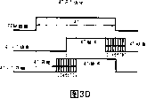
Fig. 3 A~3D explains that according to the concrete figure that optimizes example in the majorizing sequence regulating block of Fig. 1 embodiment, Fig. 3 E shows measurement 3T-pit/land and shakes the principle of selecting optimum pulse position;
Fig. 4 A and 4B are the figure that explains the writing pulse waveform of observing by measuring equipment, and this waveform is corresponding to the step S1 and the S3 of process flow diagram among Fig. 1;
Fig. 5 A and 5B are the figure that explains the writing pulse waveform of observing by measuring equipment, and this waveform is corresponding to the step S5 and the S6 of process flow diagram among Fig. 1;
Fig. 6 A and 6B are the figure that explains the writing pulse waveform of observing by measuring equipment, and this waveform is corresponding to the step S7 and the S8 of process flow diagram among Fig. 1;
Fig. 7 A and 7B are the figure that explains writing pulse waveform, and Fig. 7 A represents the figure of the writing pulse waveform observed by measuring equipment, and this waveform is corresponding to the step S9 of process flow diagram among Fig. 1, and Fig. 7 B represents the writing pulse waveform optimized by classic method;
Fig. 8 is the block scheme that comprises according to the structure of the video disc recording of the Write pulse optimizing method of the embodiment of the invention and replay device; With
Fig. 9 is the figure of used write pulse in DVD-R that explains as conventional write pulse example.
Embodiment
Fig. 1 and Fig. 2 are the process flow diagrams according to the Write pulse optimizing method process of the embodiment of the invention.
The write pulse that present embodiment relates to being used for light signal is recorded the optical disc recording apparatus of DVD-R is optimized.According to present embodiment, at first, set the shared write pulse that can not depend on various record conditions.Determine to influence the pulse desired location of recording quality successively according to the adjusting sequence, thereby obtain to be fit to the write pulse of actual operating condition.EFMplus (8~14 modulation Plus) is used as the DVD modulator approach.According to EFMplus, 8 potential source data are modulated into 16 bit data.
As above mention, DVD-R dish use rightly corresponding to two kinds of patterns, the write pulse of fundamental difference each other, described pattern is non-polymorphic type HS (at a high speed) pattern and train of impulses type LS (low speed) pattern.Therefore, according to present embodiment, the write pulse of optimizing a kind of pattern is different from the optimization to another kind of pattern slightly.To non-eurypalynous majorizing sequence corresponding among Fig. 1 by dotted line round part.The majorizing sequence of paired pulses string type corresponding among Fig. 2 by dotted line round part.
Hereinafter with reference to the operation of Fig. 1 and 2 description according to present embodiment.
In Write pulse optimizing operation according to present embodiment, at first, will use the write-in policy of the Laser Driven system of optics picked-up to be set at initial policy, (S1) gets ready.Setting recording condition (S2).Then, operation proceeds to majorizing sequence.
In non-polymorphic type operation shown in Figure 1, in first regulating block, optimize the write pulse of 4T-pit length.In this case, the negative edge of setting 4T-pit write pulse and rising edge (finishing and beginning) are (S3).In ensuing regulating block, the write pulse of setting all pit length (all-T) wherein each negative edge (end) (S4).In regulating block subsequently, the write pulse of setting all pit length (all-T) wherein each rising edge (beginning) (S4).
In ensuing regulating block, set the negative edge and the rising edge (S6) of 4T-pit write pulse once more.In regulating block subsequently, set the negative edge and the rising edge (S7) of 3T-pit write pulse.In ensuing regulating block, set 5T~14T-pit write pulse wherein the negative edge of the pulse of each (head finishes) and tail thereof rising edge (tail begins) (S8).
In the above setting of step S3~S8, the jitter measurement value of 3T-land write pulse is used as the evaluating that is used to determine.In regulating block subsequently, use 3T-pit jitter measurement value as evaluating, set the rising edge (S9) of 3T-land write pulse.In other words, optimum uses the 3T-land jitter value as evaluating, because whole recording quality can be provided, compensates and control without luminous power.In some cases, according to adjusting position, can use 3T-pit jitter value or 3T-land and 3T-pit jitter value and.
After these are optimized, when 3T-land jitter value or another jitter value must be measured, check luminous power border (S10).Obtain a new write-in policy (S11).As needs, this process turns back to step S2.The record condition of Change Example such as environment temperature etc., and repeat majorizing sequence.At last, select optimum recording conditions (S12).This process stops.
On the other hand, in the operation of train of impulses type, initial setting write-in policy (S1), setting recording condition (S2), subsequently, this process proceeds to majorizing sequence shown in Figure 2.
In first regulating block, optimize the write pulse of all pit length (all-T), promptly set the rising edge of each pulse and negative edge (beginning and finish) (S13).In ensuing regulating block, the rising edge (beginning) of setting the tail of each pit length (S14).In regulating block subsequently, set each pit length the end pulse rising edge (beginning) (S15).In ensuing regulating block, set each pit length train of impulses a plurality of pulses wherein each rising edge (beginning) (S16).
In ensuing regulating block, the rising edge (beginning) of setting 3T-pit pulse (S17).In regulating block subsequently, the rising edge (beginning) of setting 3T-land pulse (S18).
After these are optimized, check luminous power border (S19).This process proceeds to step S11 and later step thereof.Change record condition as required, and repeat majorizing sequence.At last, select optimum recording conditions (S12).Then, this process stops.
In the operation of train of impulses type, substantially the same in evaluating and the operation of non-polymorphic type.
Fig. 3 A~3D is the figure that explains the instantiation that is optimized in each regulating block.
In each regulating block, in preset range, change in the pulse setup parameter, regulate record condition, tentative tracer signal (test record), and measure the jitter value that obtains by detecting replay signal.Repeat to comprise the process of above step, i.e. the interim setting of pulse setup parameter, luminous power control, test record, playback and jitter measurement.Based on measurement result, determine the pulse setup parameter of each regulating block.
Fig. 3 A shows the regulating block among the step S3~S7 of Fig. 1 process flow diagram.Fig. 3 C shows an operation in the regulating block.With reference to Fig. 3 B, the step S3 among Fig. 3 A~S7 is classified as shown by arrows.In each regulating block, carry out the process among Fig. 3 C.
In other words, in the regulating block of Fig. 3 C, the interim setting (S21) of repetition pulse setup parameter (position), luminous power control (S22), test record (S23), playback and jitter measurement (S24).
Measurement result by jitter value is drawn the second approximation curve.Based on the second approximation curve, determine pulse setup parameter (position) (S25).This process proceeds to ensuing regulating block.
Fig. 3 D shows the operation of the regulating block that is used to optimize the 4T-pit pulse.
Shown in Fig. 3 D, in the pulse position of little spacing ground translation as the rising edge of 4T-pit pulse and negative edge, the duplicate measurements shake.The record measurement result.
Fig. 3 E shows and measures the principle that the 3T-pit/land jitter value is selected optimum pulse position.
Shown in Fig. 3 E, the second approximation curve is to draw according to measured jitter value.Determine the optimum optimization position based on minimum value.Under the situation shown in Fig. 3 E, pulse position 5 is corresponding to minimum value.This value is confirmed as optimal value.This process proceeds to ensuing regulating block.The optimal value of regulating impulse position.Final optimal value is to determine in mode progressively.
Fig. 4 A~Fig. 7 A is the figure that explains by the writing pulse waveform that measuring equipment observed, and these waveforms are corresponding to the step S1 in Fig. 1 process flow diagram, S3 and S5~S9.
With reference to Fig. 4 A, as for the recording quality of initial policy, (mark, the duration of each pulse mark) is longer to form 4T-pit.(at interval, space), each period, (T) clearly do not separate each other for land.Jitter value is higher.Obviously, signal quality is lower.But this recording quality is improved with each regulating step.When 3T-land optimizes end, obviously, realized optimization, without any problem.
Therefore, this shows by the recording quality according to the Write pulse optimizing of present embodiment and is comparable to the strategy of writing that passes through classic method optimization shown in Fig. 7 B.
Measure this situation of jitter value under the condition of the setting of fixation measuring equipment, if bigger variation takes place the pulse length of the pulse length of formed pit and formed land, then error can appear in measured value.Therefore, common jitter measurement requires to obtain accurate value, comprises that the window of measuring equipment is set.When using curve of approximation resembling in the present embodiment, big error can not appear.In other words, present embodiment advantage is not need high measuring accuracy.
As mentioned above, according to the optimization method of present embodiment, the minimum value of only passing through to select jitter measurement value boundary curve has just realized the write pulse adjusting as optimum setting.Therefore, valuably, unfamiliar slip-stick artist can easily be optimized.
Now Short Description is comprised video disc recording and replay device according to the Write pulse optimizing method of present embodiment.
Fig. 8 is the block scheme of the structure of used video disc recording of present embodiment and replay device.
With reference to Fig. 8, video disc recording and replay device comprise: disk drive unit 20 is used to drive for example CD 10 of DVD-R; Optics intake device 30, be used for laser beam flying to the CD 10 with record or playback information signal; Driving control unit 40 is used for disk drive unit 20 or optics intake device 30 are carried out servocontrol; Signal record/playback unit 50 is used to handle the information signal that writes down or reset by optics intake device 30; With data I/O unit 60, be used to receive and generate from/to external unit (not shown) record and the information signal reset.
Above-mentioned serial Write pulse optimizing process is carried out automatically by for example control circuit in signal record/playback unit 50 or microcomputer.
Utilize the example of DVD-R, explained above embodiment as optical record medium.The invention is not restricted to this medium.The present invention also can be applicable to maybe can write down blue dish (BD-R, the Write pulse optimizing that CD-R Blu-ray) drives being used for writing down CD (CD-R).
And, can optimize erasing pulse used in the rewriting or write pulse similarly according to the present invention.Like this, the present invention also is used in and is used for rewriteeing the Write pulse optimizing that CD-RW that CD (CD-RW), rewritable DVD (DVD-RW), rewritable DVD plus (DVD+RW) maybe can rewrite BD (BD-RE) drives.And, be applied to recordable DVD plus (DVD+R) equally.In addition, the present invention also can be applied to the recording method of the various CD media that will occur future similarly.
Claims (4)
1. Write pulse optimizing method is used for changing according to the length that records the pit that optical recording media will form at the write pulse that will serve as information signal the setup parameter of write pulse, and to optimize described write pulse, this method may further comprise the steps:
First step is set shared write pulse, and it does not rely on record condition separately, and the whole recording operation of influence; With
Second step comprises a plurality of regulating blocks, is used for optimizing according to record condition separately the setup parameter of the write pulse of each pit length, wherein
In described first step, set after the shared write pulse, carry out regulating block in described second step with predefined procedure, with the majorizing sequence that the setup parameter of described write pulse is progressively regulated,
Wherein in each described regulating block, repetition is regulated record condition when changing described pulse setup parameter in preset range, carry out the test signal record, and measure by detecting the process of the jitter value that replay signal obtained, and determine the pulse setup parameter of described regulating block from measurement result, the wherein said jitter value that records is made up of land jitter value and pit jitter value.
2. the method for claim 1 wherein in each described regulating block, is drawn the second approximation curve by the measurement result of described jitter value, and based on described second approximation curve, determines the pulse setup parameter of described regulating block.
3. method as claimed in claim 2, wherein in each described regulating block, the minimum value from the second approximation curve of being drawn by described jitter value is determined the pulse setup parameter of described regulating block.
4. method as claimed in claim 2, wherein in the test signal record of each described regulating block, repeat to comprise the process of interim setting, luminous power control, test record, playback and the jitter measurement of described pulse setup parameter, subsequently, determine described pulse setup parameter by a plurality of jitter measurement values.
Applications Claiming Priority (2)
| Application Number | Priority Date | Filing Date | Title |
|---|---|---|---|
| JP2004019651A JP2005216347A (en) | 2004-01-28 | 2004-01-28 | Recording pulse optimization method |
| JP019651/2004 | 2004-01-28 |
Publications (2)
| Publication Number | Publication Date |
|---|---|
| CN1664935A CN1664935A (en) | 2005-09-07 |
| CN100347763C true CN100347763C (en) | 2007-11-07 |
Family
ID=34903809
Family Applications (1)
| Application Number | Title | Priority Date | Filing Date |
|---|---|---|---|
| CNB2005100051305A Expired - Fee Related CN100347763C (en) | 2004-01-28 | 2005-01-28 | Write pulse optimizing method |
Country Status (5)
| Country | Link |
|---|---|
| US (1) | US20050207307A1 (en) |
| JP (1) | JP2005216347A (en) |
| KR (1) | KR20050077486A (en) |
| CN (1) | CN100347763C (en) |
| TW (1) | TW200535824A (en) |
Families Citing this family (6)
| Publication number | Priority date | Publication date | Assignee | Title |
|---|---|---|---|---|
| US20060239166A1 (en) * | 2005-04-20 | 2006-10-26 | Chih-Ching Yu | Method of determining a write strategy |
| KR100717862B1 (en) * | 2006-03-07 | 2007-05-14 | 엘지전자 주식회사 | Write strategy table tunning method and apparutus thereof |
| KR100696838B1 (en) * | 2006-03-30 | 2007-03-19 | 주식회사 대우일렉트로닉스 | Recording method for optical recorder |
| KR100696839B1 (en) * | 2006-03-30 | 2007-03-19 | 주식회사 대우일렉트로닉스 | Recording method for optical recorder |
| JP4561699B2 (en) * | 2006-06-26 | 2010-10-13 | 日本ビクター株式会社 | Recording / playback device |
| KR20080087315A (en) * | 2007-03-26 | 2008-10-01 | 삼성전자주식회사 | Appratus and method for detecting write strategy, apparatus and method for reproducing data |
Citations (5)
| Publication number | Priority date | Publication date | Assignee | Title |
|---|---|---|---|---|
| WO1998025267A1 (en) * | 1996-12-06 | 1998-06-11 | Koninklijke Philips Electronics N.V. | Method and apparatus for writing optical recording media |
| CN1252151A (en) * | 1997-12-08 | 2000-05-03 | 皇家菲利浦电子有限公司 | Method and device for writing optical record carriers |
| CN1397067A (en) * | 2000-12-04 | 2003-02-12 | 皇家菲利浦电子有限公司 | Method and optical recording apparatus for determining optimum write power |
| CN1416566A (en) * | 2000-11-17 | 2003-05-07 | 皇家菲利浦电子有限公司 | Mothods, optical recording appts. using such methods and optical recording medium for use by methods and appts. |
| WO2004001730A1 (en) * | 2002-06-20 | 2003-12-31 | Koninklijke Philips Electronics N.V. | Method and device for determining a set of recording pulse series parameters for optical carrier recording and optical record carrier |
Family Cites Families (1)
| Publication number | Priority date | Publication date | Assignee | Title |
|---|---|---|---|---|
| DE69931150T2 (en) * | 1998-11-06 | 2007-03-01 | Matsushita Electric Industrial Co., Ltd., Kadoma | METHOD AND DEVICE FOR DETERMINING CONDITIONS ON A RECORDING PULSE OF AN OPTICAL PLATE |
-
2004
- 2004-01-28 JP JP2004019651A patent/JP2005216347A/en active Pending
-
2005
- 2005-01-26 US US11/042,153 patent/US20050207307A1/en not_active Abandoned
- 2005-01-27 KR KR1020050007505A patent/KR20050077486A/en not_active Application Discontinuation
- 2005-01-28 CN CNB2005100051305A patent/CN100347763C/en not_active Expired - Fee Related
- 2005-01-28 TW TW094102754A patent/TW200535824A/en not_active IP Right Cessation
Patent Citations (5)
| Publication number | Priority date | Publication date | Assignee | Title |
|---|---|---|---|---|
| WO1998025267A1 (en) * | 1996-12-06 | 1998-06-11 | Koninklijke Philips Electronics N.V. | Method and apparatus for writing optical recording media |
| CN1252151A (en) * | 1997-12-08 | 2000-05-03 | 皇家菲利浦电子有限公司 | Method and device for writing optical record carriers |
| CN1416566A (en) * | 2000-11-17 | 2003-05-07 | 皇家菲利浦电子有限公司 | Mothods, optical recording appts. using such methods and optical recording medium for use by methods and appts. |
| CN1397067A (en) * | 2000-12-04 | 2003-02-12 | 皇家菲利浦电子有限公司 | Method and optical recording apparatus for determining optimum write power |
| WO2004001730A1 (en) * | 2002-06-20 | 2003-12-31 | Koninklijke Philips Electronics N.V. | Method and device for determining a set of recording pulse series parameters for optical carrier recording and optical record carrier |
Also Published As
| Publication number | Publication date |
|---|---|
| JP2005216347A (en) | 2005-08-11 |
| US20050207307A1 (en) | 2005-09-22 |
| CN1664935A (en) | 2005-09-07 |
| TW200535824A (en) | 2005-11-01 |
| KR20050077486A (en) | 2005-08-02 |
| TWI296798B (en) | 2008-05-11 |
Similar Documents
| Publication | Publication Date | Title |
|---|---|---|
| US8289827B2 (en) | Recording medium, optical disk apparatus and writing method | |
| JP4267685B2 (en) | Optical information recording method, information recording medium, reproducing method, and reproducing apparatus | |
| CN100347763C (en) | Write pulse optimizing method | |
| WO2005066940A1 (en) | Method and device for optical recording onto optical disc medium | |
| CN1490791A (en) | Multiple pulse pattern and graph controllable compact disc recorder | |
| JP4350733B2 (en) | Method for recording data on an optical recording medium | |
| CN1306489C (en) | Recording condition setting method and information recorder using same | |
| CN1855281A (en) | Method of determining a write strategy in optical storage device and optical storage device | |
| CN1598936A (en) | Information recording method and information recording medium | |
| KR100586908B1 (en) | Method for information recording and medium therefor | |
| JP2003123251A (en) | Method and device for recording data on optical recording medium | |
| JP2003257033A5 (en) | ||
| CN1294566C (en) | Information recording method, and optical disk apparatus | |
| US20030081518A1 (en) | Recording power adjusting method and optical information record apparatus using the same | |
| CN1375823A (en) | Optical recording pulse generator and method for generating optical recording pulse | |
| US7755990B2 (en) | Information recording device, information recording method, and information recording program | |
| US20030147321A1 (en) | Recording power adjusting method and optical information record apparatus using the same | |
| CN102081931B (en) | Optical disc recording method and optical disc recorder | |
| CN1806278A (en) | Information recording method and information recording device | |
| KR100607973B1 (en) | Apparatus for recording data on an optical recording medium | |
| KR100608030B1 (en) | Method and apparatus for recording data on an optical recording medium | |
| JP2008198353A (en) | Recording medium, optical disk apparatus, and writing method | |
| CN1938763A (en) | Information recording device, information recording method, and information recording program |
Legal Events
| Date | Code | Title | Description |
|---|---|---|---|
| C06 | Publication | ||
| PB01 | Publication | ||
| C10 | Entry into substantive examination | ||
| SE01 | Entry into force of request for substantive examination | ||
| C14 | Grant of patent or utility model | ||
| GR01 | Patent grant | ||
| C17 | Cessation of patent right | ||
| CF01 | Termination of patent right due to non-payment of annual fee |
Granted publication date: 20071107 Termination date: 20100301 |