CN100342436C - Optical scanning device - Google Patents
Optical scanning device Download PDFInfo
- Publication number
- CN100342436C CN100342436C CNB038242516A CN03824251A CN100342436C CN 100342436 C CN100342436 C CN 100342436C CN B038242516 A CNB038242516 A CN B038242516A CN 03824251 A CN03824251 A CN 03824251A CN 100342436 C CN100342436 C CN 100342436C
- Authority
- CN
- China
- Prior art keywords
- record carrier
- shaven head
- optical element
- light
- light beam
- Prior art date
- Legal status (The legal status is an assumption and is not a legal conclusion. Google has not performed a legal analysis and makes no representation as to the accuracy of the status listed.)
- Expired - Fee Related
Links
Images


Classifications
-
- G—PHYSICS
- G11—INFORMATION STORAGE
- G11B—INFORMATION STORAGE BASED ON RELATIVE MOVEMENT BETWEEN RECORD CARRIER AND TRANSDUCER
- G11B7/00—Recording or reproducing by optical means, e.g. recording using a thermal beam of optical radiation by modifying optical properties or the physical structure, reproducing using an optical beam at lower power by sensing optical properties; Record carriers therefor
- G11B7/12—Heads, e.g. forming of the optical beam spot or modulation of the optical beam
- G11B7/135—Means for guiding the beam from the source to the record carrier or from the record carrier to the detector
- G11B7/1356—Double or multiple prisms, i.e. having two or more prisms in cooperation
-
- G—PHYSICS
- G11—INFORMATION STORAGE
- G11B—INFORMATION STORAGE BASED ON RELATIVE MOVEMENT BETWEEN RECORD CARRIER AND TRANSDUCER
- G11B7/00—Recording or reproducing by optical means, e.g. recording using a thermal beam of optical radiation by modifying optical properties or the physical structure, reproducing using an optical beam at lower power by sensing optical properties; Record carriers therefor
- G11B7/08—Disposition or mounting of heads or light sources relatively to record carriers
- G11B7/085—Disposition or mounting of heads or light sources relatively to record carriers with provision for moving the light beam into, or out of, its operative position or across tracks, otherwise than during the transducing operation, e.g. for adjustment or preliminary positioning or track change or selection
- G11B7/08505—Methods for track change, selection or preliminary positioning by moving the head
- G11B7/08517—Methods for track change, selection or preliminary positioning by moving the head with tracking pull-in only
-
- G—PHYSICS
- G11—INFORMATION STORAGE
- G11B—INFORMATION STORAGE BASED ON RELATIVE MOVEMENT BETWEEN RECORD CARRIER AND TRANSDUCER
- G11B7/00—Recording or reproducing by optical means, e.g. recording using a thermal beam of optical radiation by modifying optical properties or the physical structure, reproducing using an optical beam at lower power by sensing optical properties; Record carriers therefor
- G11B7/12—Heads, e.g. forming of the optical beam spot or modulation of the optical beam
- G11B7/135—Means for guiding the beam from the source to the record carrier or from the record carrier to the detector
- G11B7/1365—Separate or integrated refractive elements, e.g. wave plates
- G11B7/1369—Active plates, e.g. liquid crystal panels or electrostrictive elements
-
- G—PHYSICS
- G11—INFORMATION STORAGE
- G11B—INFORMATION STORAGE BASED ON RELATIVE MOVEMENT BETWEEN RECORD CARRIER AND TRANSDUCER
- G11B7/00—Recording or reproducing by optical means, e.g. recording using a thermal beam of optical radiation by modifying optical properties or the physical structure, reproducing using an optical beam at lower power by sensing optical properties; Record carriers therefor
- G11B7/12—Heads, e.g. forming of the optical beam spot or modulation of the optical beam
- G11B7/135—Means for guiding the beam from the source to the record carrier or from the record carrier to the detector
- G11B7/1372—Lenses
- G11B7/1378—Separate aberration correction lenses; Cylindrical lenses to generate astigmatism; Beam expanders
-
- G—PHYSICS
- G11—INFORMATION STORAGE
- G11B—INFORMATION STORAGE BASED ON RELATIVE MOVEMENT BETWEEN RECORD CARRIER AND TRANSDUCER
- G11B7/00—Recording or reproducing by optical means, e.g. recording using a thermal beam of optical radiation by modifying optical properties or the physical structure, reproducing using an optical beam at lower power by sensing optical properties; Record carriers therefor
- G11B7/12—Heads, e.g. forming of the optical beam spot or modulation of the optical beam
- G11B7/14—Heads, e.g. forming of the optical beam spot or modulation of the optical beam specially adapted to record on, or to reproduce from, more than one track simultaneously
-
- G—PHYSICS
- G11—INFORMATION STORAGE
- G11B—INFORMATION STORAGE BASED ON RELATIVE MOVEMENT BETWEEN RECORD CARRIER AND TRANSDUCER
- G11B7/00—Recording or reproducing by optical means, e.g. recording using a thermal beam of optical radiation by modifying optical properties or the physical structure, reproducing using an optical beam at lower power by sensing optical properties; Record carriers therefor
- G11B2007/0003—Recording, reproducing or erasing systems characterised by the structure or type of the carrier
- G11B2007/0009—Recording, reproducing or erasing systems characterised by the structure or type of the carrier for carriers having data stored in three dimensions, e.g. volume storage
- G11B2007/0013—Recording, reproducing or erasing systems characterised by the structure or type of the carrier for carriers having data stored in three dimensions, e.g. volume storage for carriers having multiple discrete layers
Abstract
An optical head for use in the scanning of a record carrier, the record carrier having data stored on data tracks therein on a plurality of information layers (3, 4) at a plurality of depths within the record carrier. The optical head comprises: a movable optical element (16) arranged in an optical path to act upon a first radiation beam (12) and a second radiation beam (14) to provide the beams with a different displacement perpendicular to the optical path; and a lens system for focusing said first beam (12) at a first focal point (A) on a first information layer (3) of the record carrier and the focusing of the second beam (14) at a second different focal point (B) on a second information layer (4), wherein a spacing, transverse to the data tracks, between said first and second focal points (A, B) is controllable by varying the configuration of the movable optical element.
Description
Technical field
The present invention relates to a kind of optical scanning device and use therein shaven head that is used for scanning optical record carrier.The present invention especially but not exclusively relate to a kind of equipment that is used for scanning simultaneously two different Information Levels of multi layer record carrier.
Background technology
EP-A-0837455 has described a kind of optical scanning device that is used for scanning simultaneously at least two Information Levels, and it has utilized different segment beam aspect polarization direction and propagation performance.This equipment comprises radiating light source, the polarizing prism type beam splitter that is used to provide the input radiation light beam, and the birefringence collimation lens, be used to produce projection by object lens to scan two different light beams of different Information Levels.This birefringent lens provides wavefront difference to read different Information Levels between light beam, does not still allow the interval variation between the different Information Levels, the variation of perhaps different Information Level inner orbits position.
JP-A-10149560 has described a kind of optical scanning device that is used for scanning simultaneously at least two Information Levels.This equipment comprises the radiating light source that is used to provide a radiation laser beam, beam splitter, collimation lens, has the polarizer of optics single axial birefringence (being used for radiation laser beam is become at two different radiation laser beams aspect polarization direction and the propagation performance), and object lens.Equally, the wavefront difference between the light beam is fixed.
JP-A-2000195097 has described optical scanning (read or the write) equipment that is used to scan a plurality of Information Levels.In one embodiment, this equipment comprises object lens and a plurality of radiating light sources and relevant beam splitter, first's light beam is coupled with a plurality of segment beams that are used to scan different Information Levels being used for.In a plurality of segment beams each changes the scan characteristic of the light beam that is used for different layers by the element that can independently move.In another embodiment, this equipment comprises a plurality of object lens and an independent radiating light source, and the light beam that this light source produces is polarized optical element and is divided into light beam towards different object lens.Each that can independently move in the different object lens is used for the scan characteristic of the light beam of different layers with change.
Summary of the invention
According to the present invention, a kind of shaven head that is used for scanning record carrier is provided, this record carrier has the data in the data-track on a plurality of Information Levels that are stored in a plurality of degree of depth place in this record carrier, and wherein this shaven head comprises:
-being arranged on the removable optical element in the light path, it acts on first radiation laser beam and second radiation beam, thereby provides different displacements perpendicular to light path for these light beams;
-lens combination is used for described first light beam is focused on the first focus place on the first information layer of this record carrier, and second light beam is focused on second different on second Information Level focus places,
-wherein can control between described first and second focuses interval by the configuration that changes this removable optical element across data-track.
This configuration allows to read simultaneously two Information Levels of multi layer record carrier, and use common light path to change to allow the lateral separation between the Information Level data-track to two scanning beams, this variation for example is because the off-centre of one or two layer of the record carrier that is read causes.
Description of drawings
To understand other features and advantages of the present invention according to following with reference to the respective drawings description of the preferred embodiment of the present invention, these embodiment only are exemplary, in the accompanying drawings:
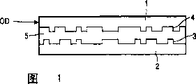
Fig. 1 represents the cross sectional representation according to the double-layer CD OD of the embodiment of the invention.
Fig. 2 has represented the synoptic diagram of assembly of optical scanning device that is used to scan double-layer CD OD according to the embodiment of the invention.
Fig. 3,4 and 5 has represented the removable optical element according to the different rotary configuration of the embodiment of the invention.
Fig. 6 has schematically shown the radial tracking according to the radiation laser beam of the embodiment of the invention.
Embodiment
Fig. 1 has represented the cross sectional representation according to the double-layer CD OD of the embodiment of the invention.CD OD comprises substrate 1 and hyaline layer 2, and at least one Information Level 3 is set between substrate and the hyaline layer.If double-layer CD as shown in the figure then is provided with two Information Levels 3,4 behind hyaline layer 2, they are positioned at the different depth place of dish.Another hyaline layer 5 with these two Information Levels separately.Hyaline layer 2 is used to protect uppermost Information Level 3, and substrate 1 simultaneously provides mechanical support.
Information can be stored in the form of optics detectable label in the Information Level 3,4 of CD, and described mark is arranged in the track (not shown in Figure 9) of substantially parallel, concentric or spiral.These marks can be that any optical readable is got form, the form in Keng form or reflection coefficient or direction of magnetization and different zone around it for example, the perhaps combination of these forms.
Fig. 2 has represented the synoptic diagram of head assemblies that is used to scan double-layer CD OD according to the embodiment of the invention.Double-layer CD OD among Fig. 2 is described identical with Fig. 1, and wherein comprises identical Reference numeral.
This scanning device comprises and is installed in the optical pick-up unit (OPU) that can move radially on the arm.This OPU comprises all component shown in Figure 2 except that CD OD.Radiating light source 6, for example single semiconductor laser send the have preset frequency radiation laser beam 7 of (for example 650nm), and it has optical axis 8.Fixed collimating lens 9 is collimated light beam with this radiation laser beam collimation.
The radiation laser beam 7 that is in collimating status passes through birefringent lenticular elements.In this embodiment, birefringent lenticular elements is a passive liquid crystal lens 10.This liquid crystal lens 10 becomes first and second light beams 12,14 respectively with radiation laser beam 7.The polarization of first and second light beams 12,14 is mutually orthogonal, and has different vergence respectively.These two light beams 12,14 all advance along optical axis 8.
The removable optical element 16 that is positioned on the optical axis 8 has variable rotation configuration status by the rotation 18 around optical axis.In this embodiment, this removable optical element is a wollaston prism 16, and it comprises birefringent prism.This wollaston prism will be followed the light beam of optical axis 8 and open in 12,14 minutes, make light beam 12,14 differently move perpendicular to optical axis 8.Folding mirror 20 reflexes to object lens 22 with light beam 12,14, and object lens 22 focus on first light beam 12 first A on the first information layer 3 of CD OD.In addition, object lens 22 also focus on second light beam 14 the difference B on second Information Level 4 that coils OD.Light beam 12,14 advances by first and second Information Levels, 3,4 reflections of dish OD and along common optics backward beam path respectively, and beam direction device 24 changes its direction.Depend on first and second light beams that the beam splitter 26 of polarization will advance along common backward beam path and opened in 12,14 minutes, make each light beam 12,14 be directed on the different needs part of detector system 28.
In the future the self-detector system is 28 is used for changing the rotation configuration of the wollaston prism 16 of closed loop servo system with the corresponding data-signal of the mutual lateral excursion of light beam that record.
Fig. 3,4 and 5 has represented to have the wollaston prism 16 that is different from rotation configuration shown in Figure 2 and described according to the embodiment of the invention.As shown in Figure 3, this wollaston prism 16 is in the first rotation configuration, and this wollaston prism radially moves first and second light beams 12,14 of the polarized orthogonal that advances along common optical axis.The result of the first rotation configuration of this wollaston prism 16 is: radial displacement line 30 has been described in the displacement between first luminous point A of first light beam 12 on the first information layer 3 and the second luminous point B of second light beam 14 on second Information Level 4.
Referring now to Fig. 6, represented to read simultaneously the track path of 3,4 o'clock light beam of Information Level 12,14, show radially spaced variation between the track path.The top track path 32 of the first luminous point A on the first information layer 3 is positioned on the different track paths 34 of the second luminous point B on second Information Level 4.Show radial displacement line 30, and it is corresponding to the first rotation configuration of wollaston prism shown in Figure 3.
Fig. 4 has represented the second rotation configuration of wollaston prism 16.In this configuration, this prism has rotated+90 ° of angles around turning axle from the first rotation configuration.Therefore, second radial displacement line 36 has been described in the displacement between current first A and second B.In Fig. 6, represented this second radial displacement line 36, and itself and first radial displacement line 30 are at an angle of 90.
Referring now to Fig. 5, show the 3rd rotation configuration of wollaston prism 16.In this configuration, this wollaston prism has rotated-90 ° of angles from the first rotation configuration around turning axle.Therefore, the 3rd radial displacement line 38 has been described in the skew between this moment first luminous point A and second luminous point B.In Fig. 6, represented the 3rd radial displacement line 38, and itself and first radial displacement line 30 are at an angle of 90.
According to described this mode,, can control the angle of radial displacement line by differently changing the rotation configuration that changes wollaston prism 16 around the anglec of rotation of turning axle.Therefore, luminous point A and B can adapt to the radially spaced any variation between first and second Information Level 3,4 that the off-centre of two Information Levels by dish OD causes.
Utilize suitable mechanical rotation mechanism (not shown) to realize of the rotation of described wollaston prism 16 around turning axle.
In this embodiment of the present invention, liquid crystal lens 10 has sourceless characteristic, and therefore utilize the loop servosystem between detector system 28 and the mechanical driver (not shown), change object lens 22 and the distance of coiling OD Information Level 3,4, realize any axial displacement of first and second light beams 14,12 and focus on an A, B, wherein mechanical driver is used to control the position of object lens 22.Be used to the data-signal relevant of self-detector system, realize the variation of object lens 22 positions with axial tracking and focusing error.
In another anticipation embodiment of the present invention, liquid crystal lens 10 comprises passive and active element.Just can change active component by applying voltage on the electrode in liquid crystal lens, this liquid crystal lens changes the vergence of outgoing beam.Therefore in this example, combine to the variable in distance of coiling the OD Information Level with object lens 22, realize the axial displacement variation of first and second light beams 3,4 and in the focusing at luminous point A, B place by attribute change with active liquid crystal lens.
Above embodiment is interpreted as exemplary embodiment of the present invention.Can predict other embodiments of the invention.
In another embodiment, imagine this wollaston prism 16 and place light path between light source 6 and the liquid crystal lens 10.
In another anticipation embodiment, removable optical element is not limited to comprise wollaston prism.The different configuration statuses of this removable optical element there is no need to realize around the mechanical rotation of turning axle by element, but can realize by for example being across the birefringence element that optical axis moves suitable configuration.
In one embodiment, the present invention is used to scan double-layer digital universal disc (DVD).Yet shaven head of the present invention has the function of the different Information Levels of other type multi layer record carrier of scanning.
Be appreciated that and also can adopt above equivalent and the modification that does not have description in the case without departing from the scope of the present invention, these equivalents and modification limit in appended claims.
Claims (14)
1. shaven head that is used for scanning record carrier, this record carrier have a plurality of Information Levels (3,4) that are stored in a plurality of degree of depth place in this record carrier and go up data in the data-track, and wherein this shaven head comprises:
-being arranged on the removable optical element (16) in the light path, it acts on first radiation laser beam (12) and second radiation laser beam (14), for these light beams provide different displacements perpendicular to light path; And
-lens combination is used for first focus (A) that described first light beam (12) focuses on the first information layer (3) of described record carrier is located, and second light beam (14) is focused on second Information Level (4) goes up different second focuses (B) and locate,
-wherein using first and second light beams (12 simultaneously by described shaven head, 14) the different Information Levels (3 of scanning record carrier, 4) during, by the interval between described first and second focuses of the configuration may command that changes described removable optical element (16) (A, B) across data-track.
2. shaven head according to claim 1, wherein said removable optical element (16) are suitable for around light path rotation (18) to obtain various configuration statuses.
3. shaven head according to claim 1 and 2, wherein said removable optical element (16) comprises the optical element that depends on polarization.
4. shaven head according to claim 3, wherein said removable optical element (16) comprises wollaston prism.
5. shaven head according to claim 3, wherein said first light beam (12) and second light beam (14) be polarization orthogonally.
6. shaven head according to claim 1 and 2, wherein said first light beam (12) and second light beam (14) be polarization orthogonally, and described lens combination comprises birefringent lenticular elements (10), and the different depth place that is used in record carrier focuses on first light beam (12) and second light beam (14).
7. shaven head according to claim 6, wherein said birefringent lenticular elements (10) comprises liquid crystal material.
8. according to front claim 1 or 2 described shaven heads, comprise a detection system (28), be used for after, detect the independent information signal in each of described first and second light beams (12,14) by the described record carrier of described first and second light beams (12,14) each beam flying.
9. shaven head according to claim 8 comprises an optical system, and this system is adapted such that described first and second light beams (12,14) are advancing along common light path in the part path of described detection system (28) after having scanned record carrier.
10. shaven head according to claim 9 comprises described removable optical element (16) in the wherein said common light path.
11., comprise described birefringent lenticular elements (10) in the wherein said common light path according to claim 9 or 10 described shaven heads.
12. according to claim 9 or 10 described shaven heads, comprise a beam splitter (26), be used for respectively described first and second light beams (12,14) guiding being the different paths towards described detection system (28).
13. according to claim 9 or 10 described shaven heads, wherein said detection system (28) is used to produce a signal that is used for changing the configuration of removable optical element (16), the lateral separation between these signal change first and second focuses (A, B).
14. an optical scanning device comprises shaven head according to claim 1 and 2.
Applications Claiming Priority (2)
| Application Number | Priority Date | Filing Date | Title |
|---|---|---|---|
| EP02079280 | 2002-10-16 | ||
| EP02079280.0 | 2002-10-16 |
Publications (2)
| Publication Number | Publication Date |
|---|---|
| CN1689085A CN1689085A (en) | 2005-10-26 |
| CN100342436C true CN100342436C (en) | 2007-10-10 |
Family
ID=32103940
Family Applications (1)
| Application Number | Title | Priority Date | Filing Date |
|---|---|---|---|
| CNB038242516A Expired - Fee Related CN100342436C (en) | 2002-10-16 | 2003-09-15 | Optical scanning device |
Country Status (9)
| Country | Link |
|---|---|
| US (2) | US20060154550A1 (en) |
| EP (1) | EP1554723B1 (en) |
| JP (1) | JP2006503389A (en) |
| KR (1) | KR20050053756A (en) |
| CN (1) | CN100342436C (en) |
| AT (1) | ATE427547T1 (en) |
| AU (1) | AU2003260849A1 (en) |
| DE (1) | DE60326976D1 (en) |
| WO (1) | WO2004036568A1 (en) |
Families Citing this family (2)
| Publication number | Priority date | Publication date | Assignee | Title |
|---|---|---|---|---|
| FR3020179B1 (en) | 2014-04-22 | 2017-10-06 | Saint Gobain | ELECTRODE SUPPORTED TRANSPARENT FOR OLED |
| DE102017215671A1 (en) * | 2017-09-06 | 2019-03-07 | Robert Bosch Gmbh | Scanning system and transmitting and receiving device for a scanning system |
Citations (3)
| Publication number | Priority date | Publication date | Assignee | Title |
|---|---|---|---|---|
| CN1180890A (en) * | 1996-10-21 | 1998-05-06 | 德国汤姆逊-布朗特公司 | Device for reading from or writing to optical recording medium |
| CN1258068A (en) * | 1998-12-21 | 2000-06-28 | 德国汤姆逊-布朗特公司 | Device for reading or writing optical recording medium having different information carrier layer |
| JP2000187880A (en) * | 1998-12-21 | 2000-07-04 | Sharp Corp | Multibeam optical pickup and multibeam generating method |
Family Cites Families (8)
| Publication number | Priority date | Publication date | Assignee | Title |
|---|---|---|---|---|
| JPS61160714A (en) * | 1985-01-09 | 1986-07-21 | Canon Inc | Vari-focal lens |
| NL9002841A (en) * | 1990-12-21 | 1992-07-16 | Philips Nv | METHOD AND APPARATUS FOR REGISTRATION, READING AND DELETING A MULTI-SPACE REGISTRATION CARRIER, AND REGISTRATION CARRIER SUITABLE FOR THIS METHOD AND APPARATUS. |
| KR100200837B1 (en) * | 1995-01-24 | 1999-06-15 | 윤종용 | Optical pickup for multi layer optical disc |
| JPH0991700A (en) * | 1995-09-25 | 1997-04-04 | Sony Corp | Method for initializing optical recording medium and initialization device used for the same |
| JPH10149560A (en) | 1996-11-15 | 1998-06-02 | Sony Corp | Optical pickup and optical disk device |
| JP3692844B2 (en) * | 1998-07-24 | 2005-09-07 | セイコーエプソン株式会社 | Electroluminescent device and electronic device |
| WO2001093254A1 (en) * | 2000-05-30 | 2001-12-06 | Thomson Licensing S.A. | Device for reading and/or writing optical recording media |
| AU2002348866A1 (en) * | 2001-12-12 | 2003-06-23 | Koninklijke Philips Electronics N.V. | Optical scanning device |
-
2003
- 2003-09-12 US US10/530,497 patent/US20060154550A1/en not_active Abandoned
- 2003-09-15 JP JP2004544525A patent/JP2006503389A/en active Pending
- 2003-09-15 CN CNB038242516A patent/CN100342436C/en not_active Expired - Fee Related
- 2003-09-15 EP EP03808783A patent/EP1554723B1/en not_active Expired - Lifetime
- 2003-09-15 AU AU2003260849A patent/AU2003260849A1/en not_active Abandoned
- 2003-09-15 WO PCT/IB2003/004022 patent/WO2004036568A1/en active Application Filing
- 2003-09-15 DE DE60326976T patent/DE60326976D1/en not_active Expired - Fee Related
- 2003-09-15 US US10/531,018 patent/US7161891B2/en not_active Expired - Fee Related
- 2003-09-15 KR KR1020057006320A patent/KR20050053756A/en not_active Application Discontinuation
- 2003-09-15 AT AT03808783T patent/ATE427547T1/en not_active IP Right Cessation
Patent Citations (3)
| Publication number | Priority date | Publication date | Assignee | Title |
|---|---|---|---|---|
| CN1180890A (en) * | 1996-10-21 | 1998-05-06 | 德国汤姆逊-布朗特公司 | Device for reading from or writing to optical recording medium |
| CN1258068A (en) * | 1998-12-21 | 2000-06-28 | 德国汤姆逊-布朗特公司 | Device for reading or writing optical recording medium having different information carrier layer |
| JP2000187880A (en) * | 1998-12-21 | 2000-07-04 | Sharp Corp | Multibeam optical pickup and multibeam generating method |
Also Published As
| Publication number | Publication date |
|---|---|
| ATE427547T1 (en) | 2009-04-15 |
| JP2006503389A (en) | 2006-01-26 |
| KR20050053756A (en) | 2005-06-08 |
| EP1554723A1 (en) | 2005-07-20 |
| US20060154550A1 (en) | 2006-07-13 |
| US7161891B2 (en) | 2007-01-09 |
| US20060077854A1 (en) | 2006-04-13 |
| EP1554723B1 (en) | 2009-04-01 |
| DE60326976D1 (en) | 2009-05-14 |
| CN1689085A (en) | 2005-10-26 |
| WO2004036568A1 (en) | 2004-04-29 |
| AU2003260849A1 (en) | 2004-05-04 |
Similar Documents
| Publication | Publication Date | Title |
|---|---|---|
| US5712842A (en) | Optical pick-up device | |
| EP0745980B1 (en) | Optical pickup device | |
| US20040130989A1 (en) | Optical head device using aberration correction device and disk drive unit | |
| EP1560209B1 (en) | Liquid crystal optical element and optical device | |
| CN100342436C (en) | Optical scanning device | |
| KR20040071697A (en) | Optical scanning device | |
| US20080212418A1 (en) | Optical disc device | |
| US8194521B2 (en) | Optical disc device, video reproducing apparatus, server, car navigation system using the optical disc device, integrated circuit and recording/reproducing method | |
| CN1602523A (en) | Optical scanning device | |
| JP2003263770A (en) | Optical recording/playback device and optical recording medium | |
| CN1137471C (en) | Read or wright photo record medium equipment | |
| JP2007114248A (en) | Liquid crystal device and optical pickup | |
| US6700854B1 (en) | Optical storage apparatus and phase compensation amount adjustment method | |
| JP3046394B2 (en) | Optical head and optical information recording device | |
| US6724711B2 (en) | Apparatuses and methods for directing light beams in an optical recording system | |
| CN1608290A (en) | Optical scanning device | |
| US7859762B2 (en) | Aberration correction apparatus | |
| JP2006040380A (en) | Optical recorder | |
| WO2003046897A2 (en) | Optical scanning device | |
| JP2007334955A (en) | Optical information recording/reproducing device | |
| JPS6310491B2 (en) | ||
| EP1728246A1 (en) | Optical device for recording and reproducing | |
| JPS6329348A (en) | Recording method for magneto-optical recording medium | |
| JP2008010085A (en) | Optical pickup device and optical disk unit using the same | |
| KR20070018882A (en) | Optical device with polarization independent phase structure system |
Legal Events
| Date | Code | Title | Description |
|---|---|---|---|
| C06 | Publication | ||
| PB01 | Publication | ||
| C10 | Entry into substantive examination | ||
| SE01 | Entry into force of request for substantive examination | ||
| C14 | Grant of patent or utility model | ||
| GR01 | Patent grant | ||
| C17 | Cessation of patent right | ||
| CF01 | Termination of patent right due to non-payment of annual fee |
Granted publication date: 20071010 Termination date: 20120915 |